Creating Conceptual mass in REVIT and Creation of Sinusoidal curve and a Parametric stadium using Dynamo
A1) Aim: To create a sinusoidal curve and surface by sinusoidal points in Dynamo.
Introduction: Dynamo is a software which is linked to Revit and where a model is created just by code. This software helps us to easily create a parametric model and can edit the model to understand the choices to be done easily.
Here Sinusoidal curves are creating by defining the sinusoidal value. Following are the procedure to create a Sinusoidal curve.
Procedure:
- Open Revit with architectural template go to manage tab > Visual programming panel > Dynamo.
- Dynamo apps opens. Now click on New. A new modelling space opens.
- To create sinusoidal curve create a open a range and set the range to set number of points required.
- Open slider and code block to define start, end and step value in range code.
- Here in this model the Start is set to 0, End 200 and step is 2 as shown in fig A10
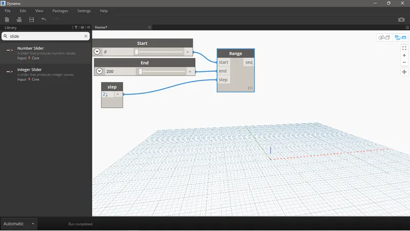
Fig A10: Setting out range.
- Now open sin code block and connect range to sin as shown in fig B10
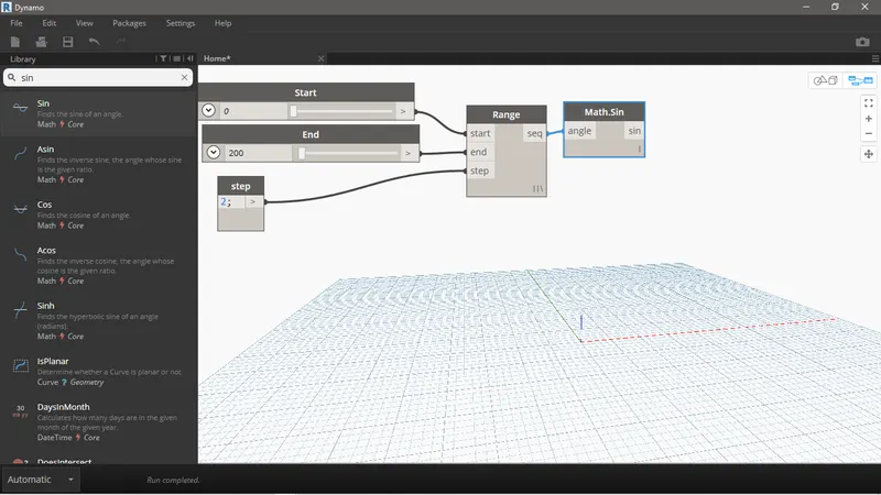
Fig B10: Setting out Math.sin for sinusoidal curve point
- Since sin is small in number to amplitude create a amplitude slider and multiply it with the sin.
- Now to create Sinusoidal points at X axis open point by coordinate ang provide range input to x axis and amplitude sin input to Z axis fig C10
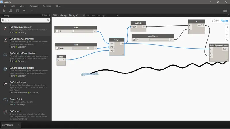
Fig C10: Sinusoidal points created.
- To change the phase create phase slider and give the input to y axis as shown in fig D10.
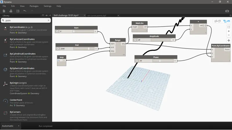
Fig D10: Creating of Phase
- Fig E10 shows sinusoidal points.
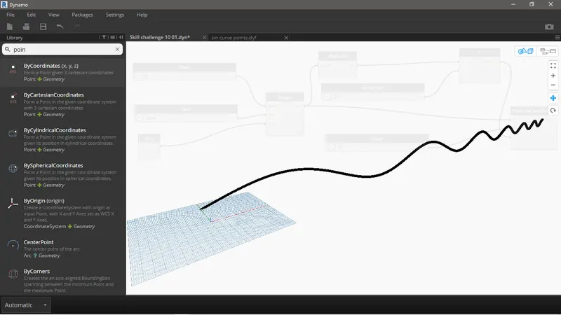
Fig E10: Sinusoidal points.
- To create sinusoidal curve line select nurbs curve by control point and give the input of point by coordinate to it. A sinusoidal line is created As shown in fig F10
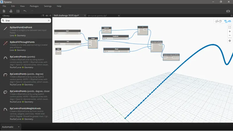
Fig F10: Setting out line curve by Nurbs curve.
- To create a surface we need to create similar curve line again for that select all the processing code as shown in fig G 10 go to Edit tab >Create node from selection.
Fig G10: Selection of processing code.
- Now edit the custom node properties as required. Here in fig H 10 shows the custom node properties saved as.
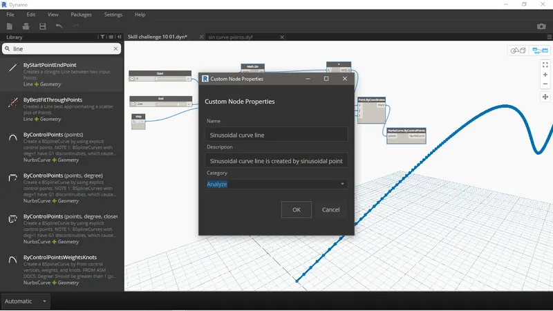
Fig H10: Saving the custom node properties.
- Fig I 10 shows that the all the processing values are grouped.
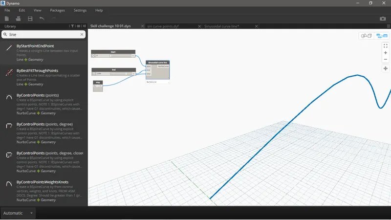
Fig I10: Custom node properties are grouped.
- Now copy the complete process and duplicate another to create another similar curve line as and change in phase, hence this will show us the similar curve line shown in fig J10.
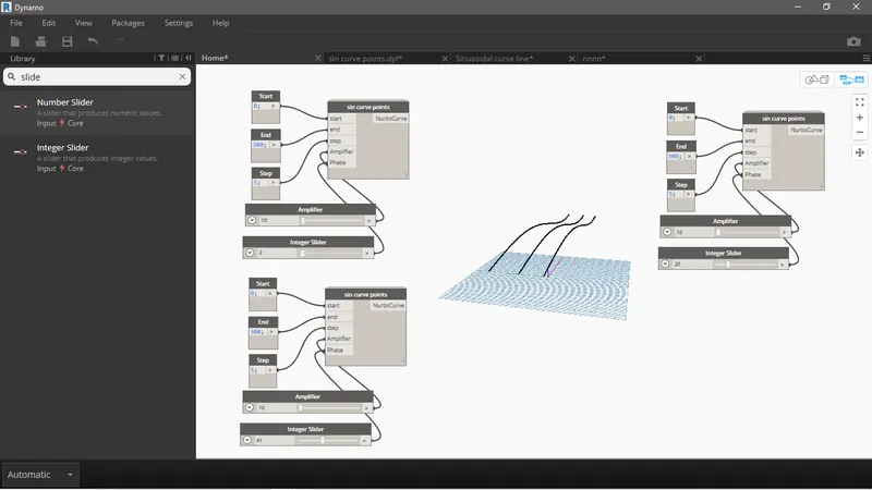
Fig J10: Cust nodes are duplicated and similar line curve are created.
- Now create the list of the curve line as shown in fig K10.
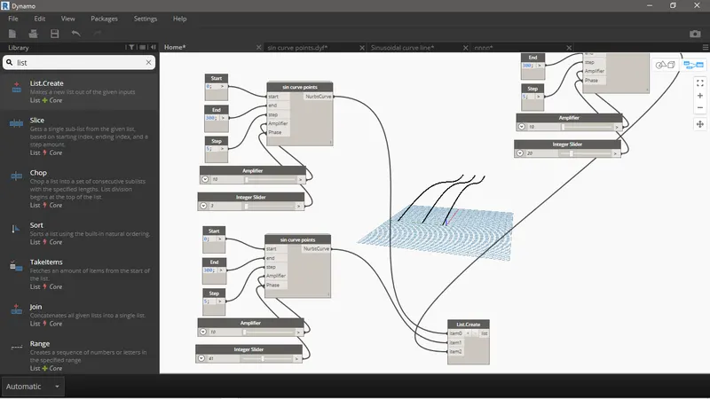
Fig K10:Creating list of curves.
- Now create sinusoidal surface curve as shown in L10.
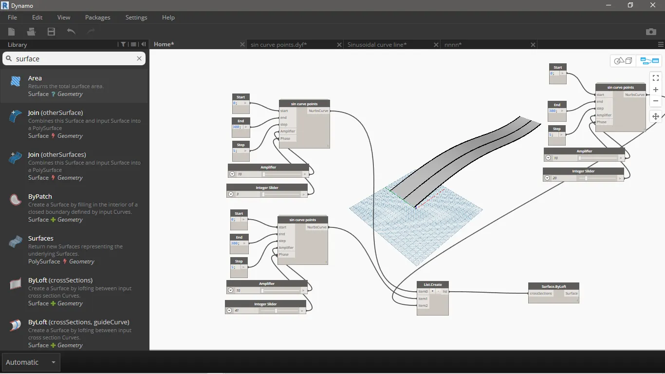
Fig L10: Sinusoidal surface.
Conclusion.
It is noticed that in Dynamo a model is created just by a linking the defined nodes.
A2) Aim: To create conceptual layout of floor plan and a wall in Dynamo.
Introduction: In Dynamo a layout of floor plan and walls can be created with the code and the type of elements is been already linked from Revit, hence achieving the same instances as available in Revit. The only pros is that we can see the changes of the model by easily altering in Dynamo.
Procedure
- Create 2 integer slider to set out the points to create a line diagram.
- Use 4 nos of Points by coordinate and naming it as Origin, 1st point, 2nd point and 3rd point and link the slider to position the points.
- Now draw the line between the points to create a layout by using line by start and end point and link the point by coordinate.
- Since the layout is created. To create the floor we need create the list to gather all the layout in one group so that it can form an outline and then create a floor type to define its instances and levels to set the floor.
- Now link all the above created list, floor type, and levels to the Floor by outline type and level. As shown in fig M10.
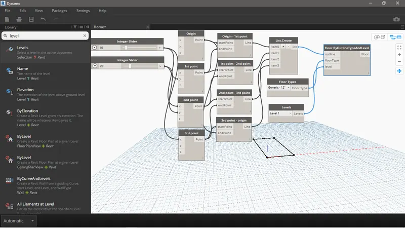
Fig M10: Nodes to create Floor.
- The fig N10 shows the floor element created by Dynamo in Revit.
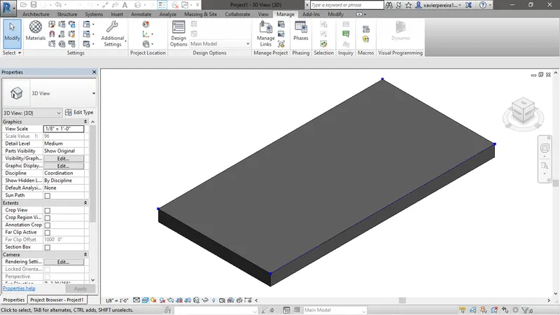
Fig N10: Floor model displayed in Revit as created by Dynamo.
- Proceeding forward to create a wall. Create an Integer slider to define wall height and wall type to define its instances.
- Using wall by curves and height and linking the list, wall height, level and wall type as shown in fig O 10.
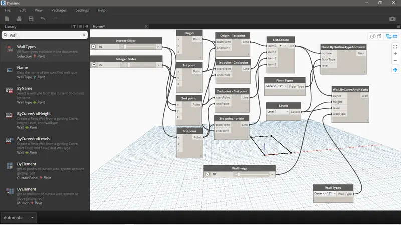
Fig O10: Nodes for Wall.
- Fig P 10 shows the walls created in Revit which is linked with Dynamo.
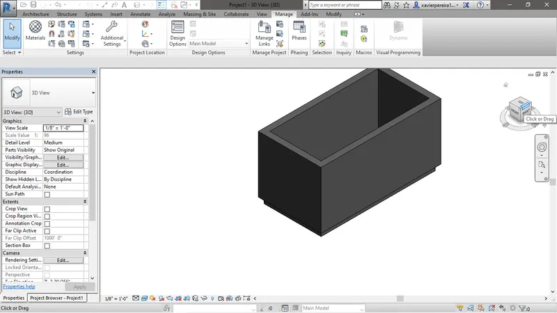
Fig P10: Wall model displayed in Revit.
Conclusion
It is to be noticed that the size of the layout and height of the wall can be easily altered and understand just by sliding the integer slider.
A3) Aim: To create a model array in Revit and change its properties in Dynamo.
Introduction: Here we can see that the Software both Revit and Dynamo are interlinked such that it shares the data to each other which helps to get the work done quite easy. This infact helps to work on the model with both the software for easy features. In this task we will create an array of model in Revit and then alter the model in Dynamo.
Procedure:
- First create an array of model element in Revit as shown in fig Q10.
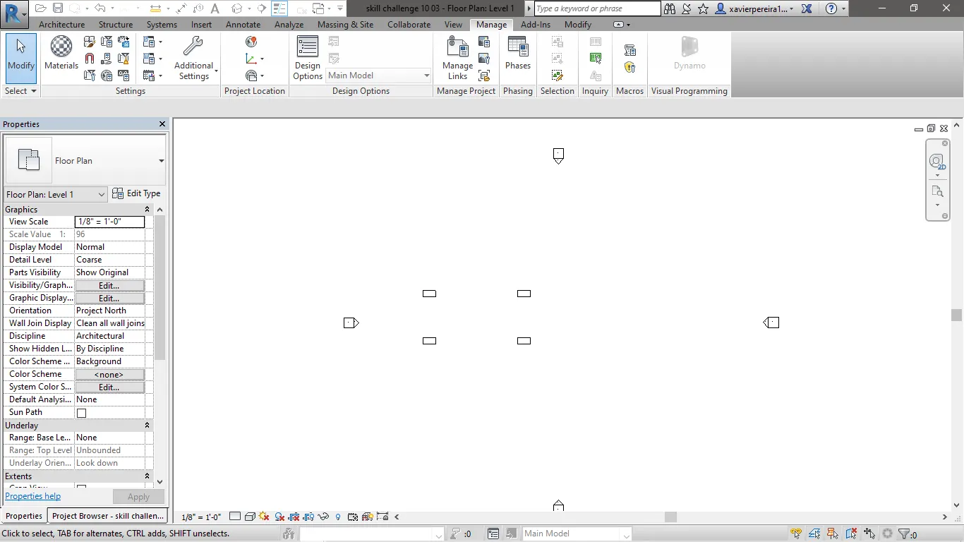
Fig Q10: An array of model element.
- Open Dynamo and open select multiple model element and select the elements from the Revit. We can see that an elements are selected in Dynamo based on numbers. As shown in fig R10.
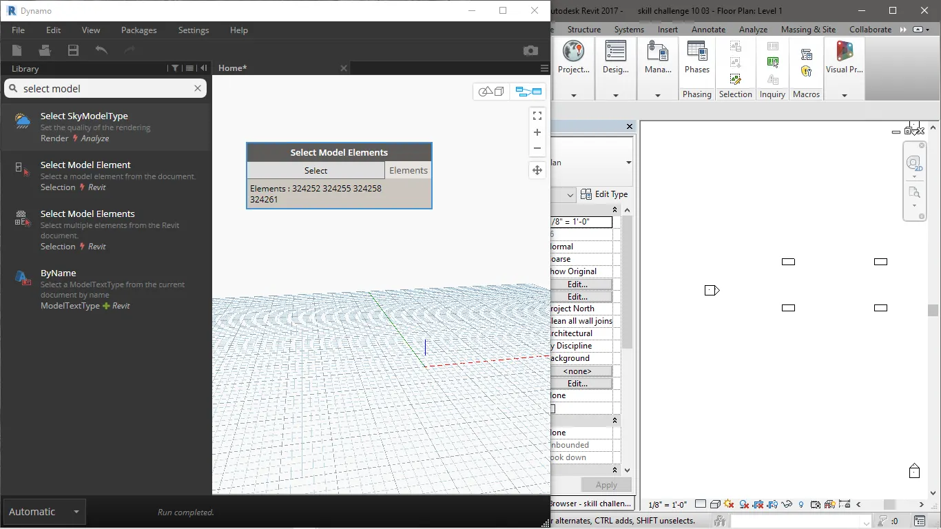
Fig R10: Model elements selected in Revit for Dynamo.
- Now to edit the instance for example to rotate the elements. Open Family instance set rotation and Integer slider. Link the select model element and integer slider to Family instance set rotation. We can see that the elements is rotated as the interger slider is slided as shown in fig S10.
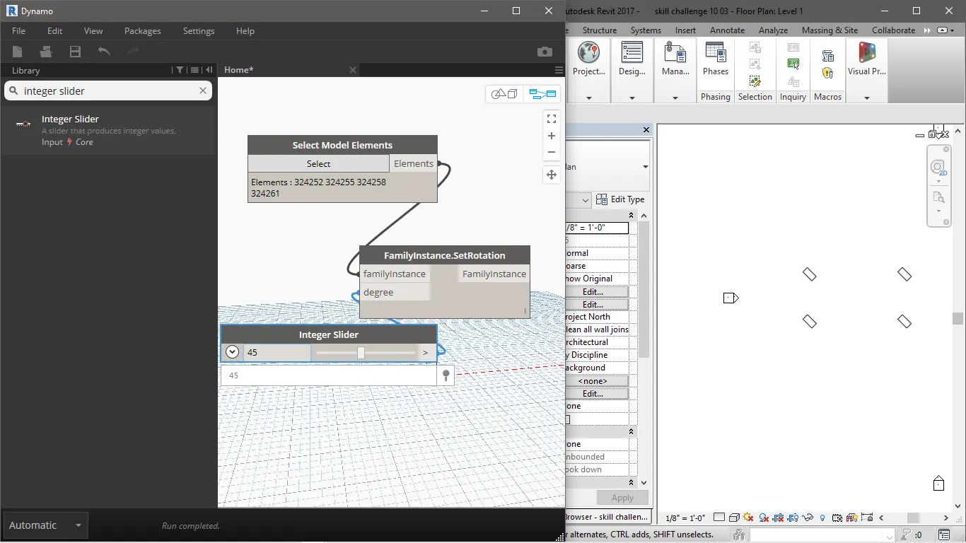
Fig S10: Nodes to rotate the model in Revit.
Conclusion.
It is concluded that the elements created in the Revit can be altered in Dynamo too.
A4) Aim: To create a parametric column using conceptual mass similar to walkway modelling with a triangle or square bend finish.
Introduction: Conceptual mass is a feature which help us to understand the concept of the architectural model and design in detail just in a flash. Here a parametric twisted Pentagon mid bulged column will be created with triangle bend finish.
Procedure
- Go to Revit file> new > Conceptual mass> Mass> open. An work plane opens as shown in fig T10.
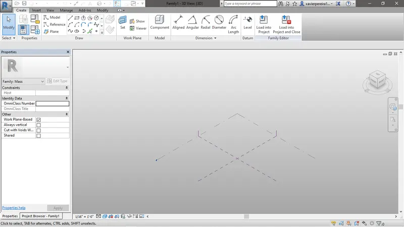
Fig T10: Conceptual mass work plane.
- To create the column discussed in introduction. First set a work plane on a Vertical plane and draw a line on that plane as shown in fig U10.
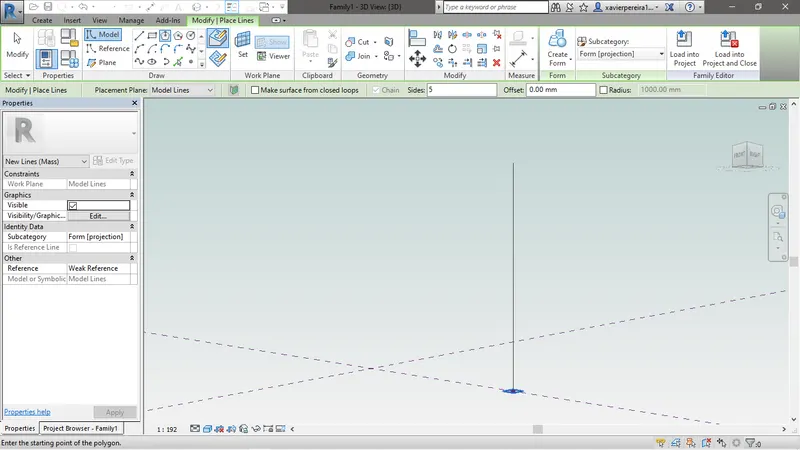
Fig U10: Vertical line drawn to a Vertical plane.
- Now to create a pentagon column shape. First set a work plane with vertical line as an axis as shown in fig V10.
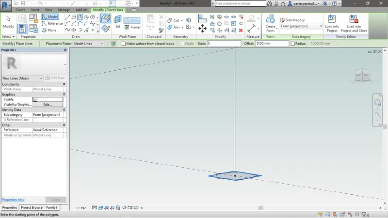
Fig V10: Setting out work plane.
- Now select inscribed polygon from draw panel in modify tab as shown in fig M10.
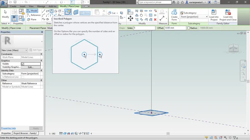
Fig W10: Location of polygon in Revit.
- Set sides as 5 and create the Pentagon geometry on the set work plane with a radius of 225mm as shown in fig X10.
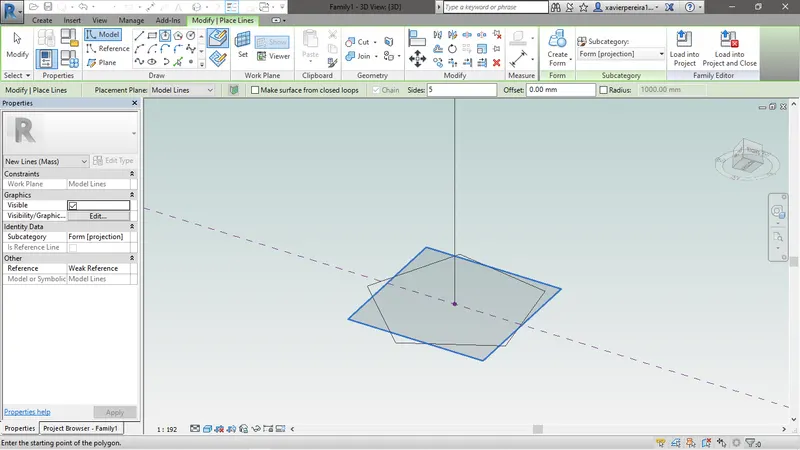
Fig X10: Setting out Pentagon outline.
- Similarly create another Pentagon at the mid of the vertical line with radius of 300mm and .at top with the radius of 225mm. As shown in fig Y 10.
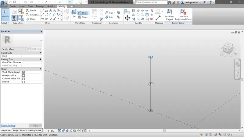
Fig Y10: Setting out pentangon outline at mid and at end.
- Now to create a surface select all 3 pentagon and go to form panel > Create form drop down > solid form. A twisted column is being formed as seen on fig Z 10.
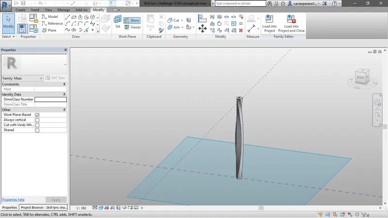
Fig Z10: Twisted pentagonal column formed.
- Now to create triangle bend pattern select the form and divide the surface by clicking on divide surface in divide panel as shown in fig AA 10.
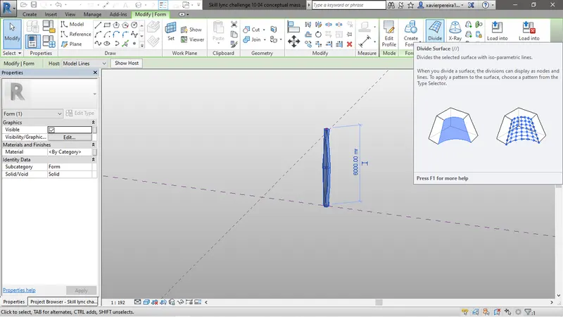
Fig AA10: Division of surface.
- In Fig AB 10 we can see that the surface is divided and in the properties triangle bent is being selected to give the finish for the surface.
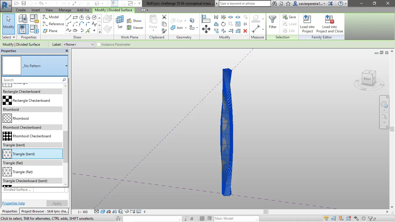
Fig AB10: Application of Finishing on the surface.
- Fig AC 10 shows the finished surface of triangle bent.
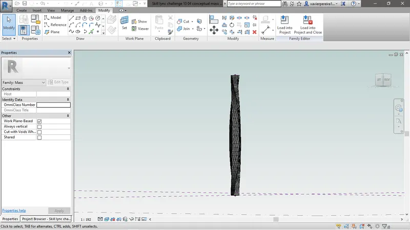
Fig AC10: Complete model of twisted pentagonal bulged column.
Conclusion
A parameteric column is created with a finishing of triangle bent.
A5) Aim: To create parametric stadium using Dynamo.
Introduction: In this task we will be creating a stadium using nodes in dynamo with the features available and giving it a parametric shape to the model.
Procedure:
- To begin with the process first create a 3 Point by coordinates nodes with different heights using linking with integer slider. In this model the name of the point is Base point, 1st point and 2nd point as shown in fig AD 10.
- Now set out a circle using 3 circle by point node and linking the base point node, 1st point node and 2nd point node and respective radius with the help of Integer slider linking to formula code block to increase and decrease the radius of the respective circle for having a paramateric shape as shown in fig AD10.
- A circle geometry is created in respective given points. Proceeding ahead to create a surface. Link the Base circle and 1st circle to the list node.
- The 2nd circle will be required to be rotated with an Y axis and then the rotated geometry will be linked to the available list. So to rotate the 2nd circle use Geometry rotate node and link the 2nd circle to geometry, 2nd base point to origin, used Y axis vector node and link it to Vector and use integer slider node and link it to degrees in the Geometry rotate node. Now link the geometry rotate node to List node and the List node will be linked to Surface by loft node As shown in fig AD 10
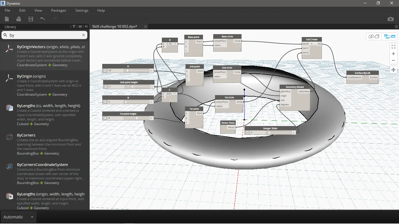
Fig AD10: Nodes to create parametric stadium
- Fig AE 10 shows the Parametric stadium model.
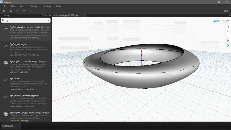
Fig AE10: Parametric stadium model.
- Now proceeding ahead to create a ground in the stadium. It is done by using a rectangle by Length and width node and having a link with 2 integer slider node to define the value of length and width of the ground as shown in fig AF 10.
- To provide thickness for the ground use Extrude as solid node and link the rectangle geometry node and a number slider node to distance as shown in AF 10.
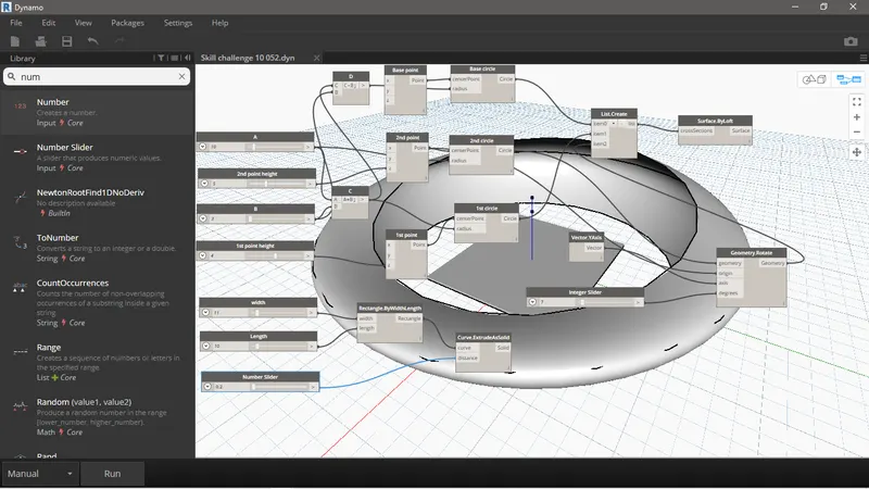
Fig AF10: Node for ground in stadium.
- Fig AG 10 shows the model of the parametric stadium with ground.
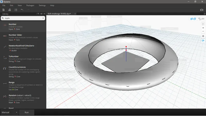
Fig AG10: Parametric stadium with ground.
- Now if we check the Revit we can see that the outline of the Parametric stadium is visible as shown in fig AH 10.
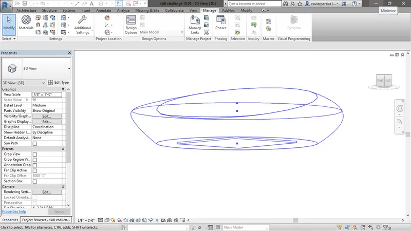
Fig AH10: Model in Revit that is created in Dynamo.
Conclusion
A sophisticated parametric model is created in Dynamo just using nodes as shown above.