Creating Conceptual mass in REVIT and Creation of Sinusoidal curve and a Parametric stadium using Dynamo
1.
AIM : Using Dynamo create a set of sinusoidal points and create a curve and create a surface out of the curve.
INTRODUCTION :
Dynamo is a visual programming add-in for autodesk revit. dynamo provides open source graphical programming, which enables custom computational design and automation process for building information modelling.
PROCEDURE :
- open revit and go to manage tab open dynamo
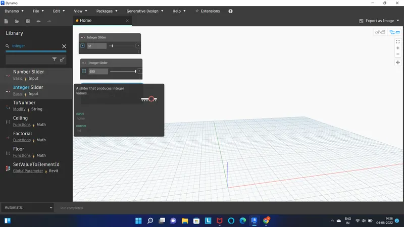
- go to search box type integer slider click the integer slider make 3 screen of it
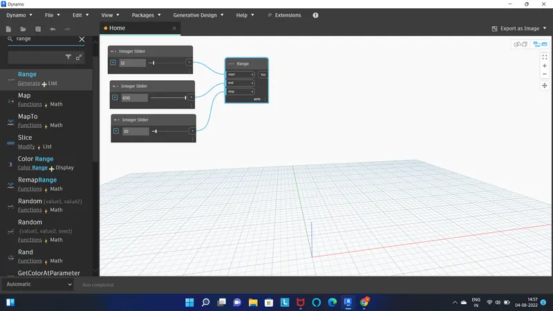
- next type range in search box select it
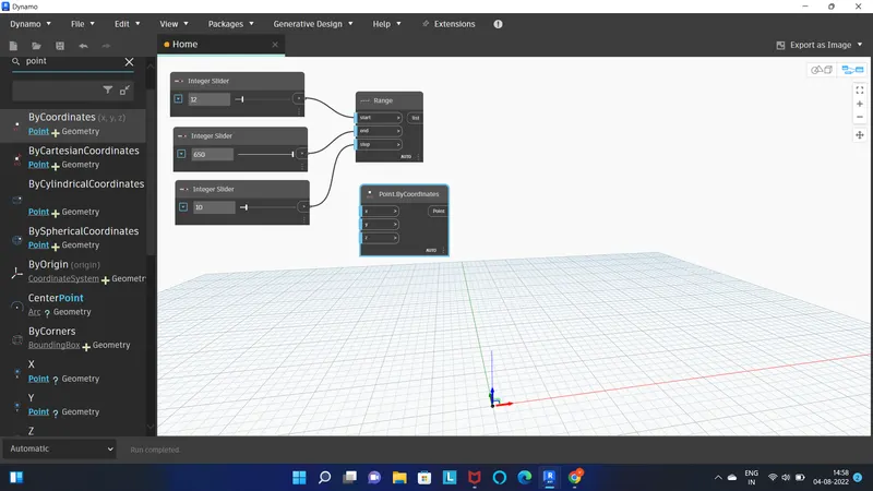
- next type point by coordinate in search box
- select point by coordinate
- for dual curve or dual sinosidal point
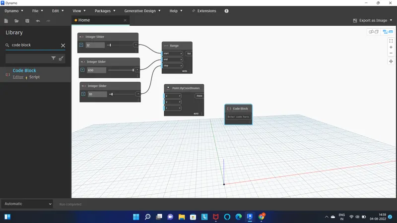
- make another point by coordinate and code block
- type code block in search box select it
- and copy paste the point by coordinate
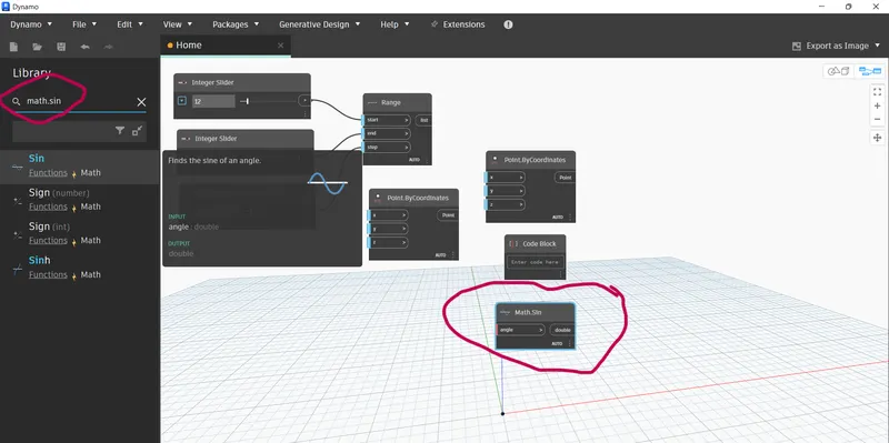
- for sinosidal curve we have to search math.sin in search box select it
- 
- connect the range to point by coordinate to X.
- type 50 in code block
- now connect the range box to another point by coordinate box to X and math sin box
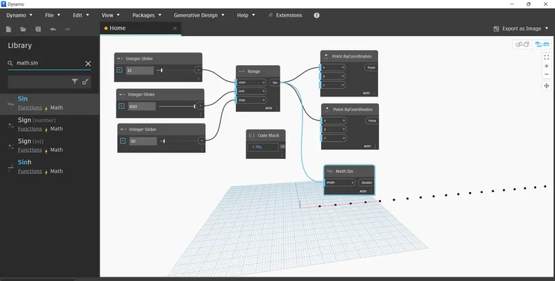
- type product in search box and select it
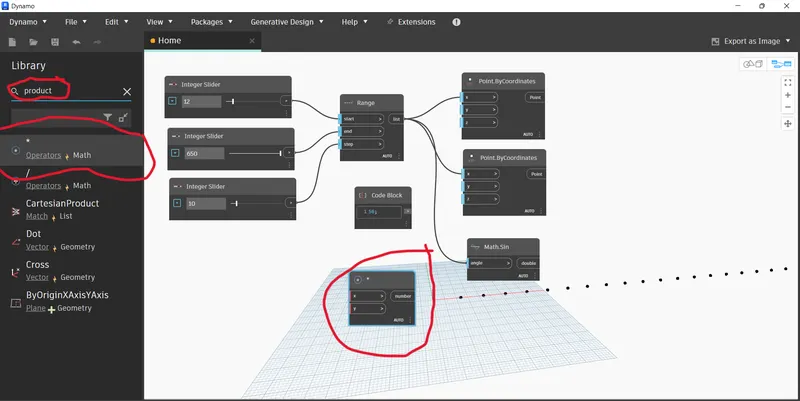
- connect the math.sin box to product box X
- connect code block box to product box Y
- connect product box to first box of point by coordinate to Z.
- we can see the point curve will appear on screen
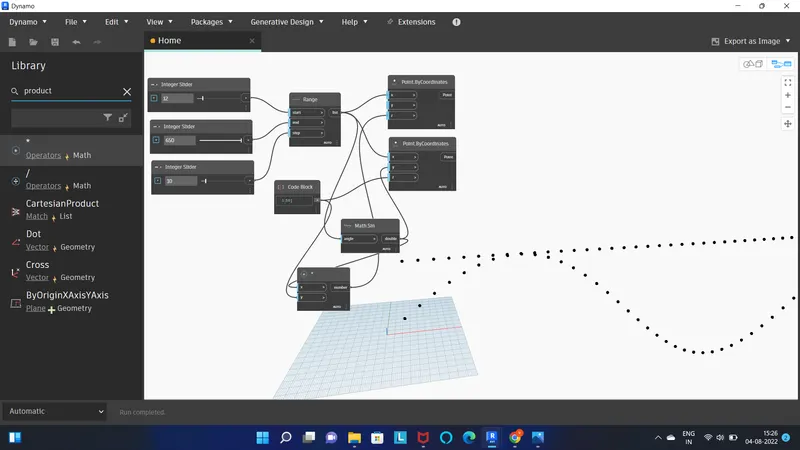
- now select the nurbs by control point in serach box and select it
- copy paste ans create another nurbs by control point
- now type list in search box select list create
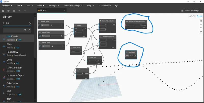
- connect the point by coordinate 1 to nurb by control point 1
- simliaarly connect the point by coordinate 2 to nurbs by control point 2
- add one more item in list create i.e . item 1
- connect the nurbs by control point 1 to list create item 0
- connect the nurbs by control point 2 to list create item 1
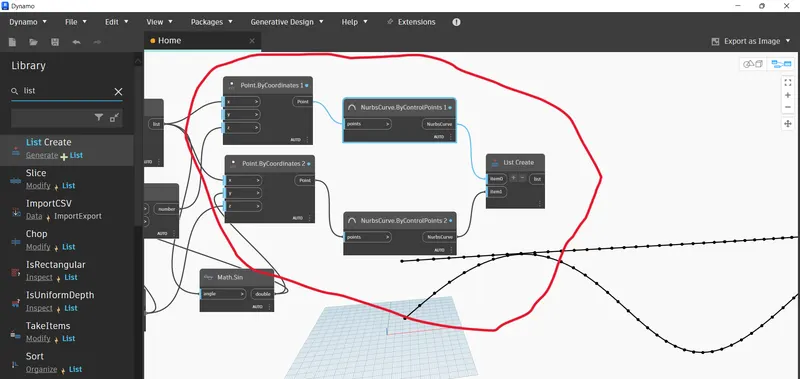
- now we need to make surface
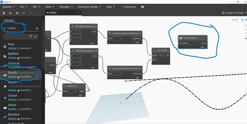
- type surface and select the surface by loft
- 
- connect the list create to cross section
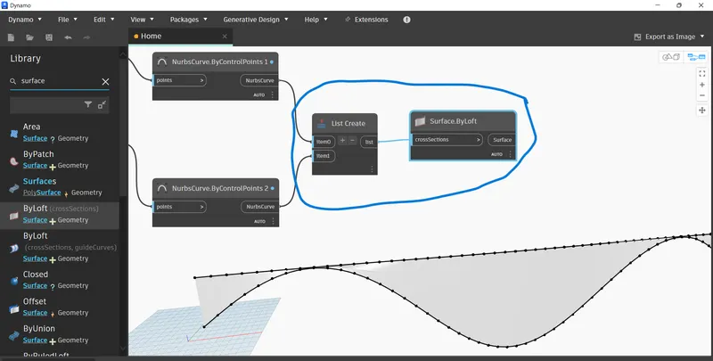
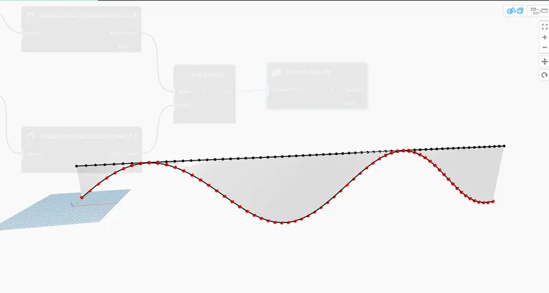
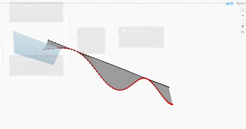
RESULT :
Using Dynamo we have created a set of sinusoidal points and created a curve and created a surface out of the curve.
2.
AIM :
Create a conceptual layout of floor plan in dynamo . Using the tools available in dynamo link the lines to appropriate model elements in Revit by choosing the wall types and wall parameters. Make use of the sliders to slide through the height of the wall and length of the wall.
INTRODUCTION :
Dynamo is a visual programming add-in for autodesk revit. dynamo provides open source graphical programming, which enables custom computational design and automation process for building information modelling.
PROCEDURE :
- open new page in dyanamo
- type integer in search box select integer slider
- make 2 integer slider box
- type point by coordiante in search box and select it
- make 4 box of point by coordinate
- connect the integer slider 1 to X of point by coordinate 1
- connect the integer slider 1 to Y of point by coordinate 2
- connect the integer slider 2 to X of point by coordinate 2
- connect the integer slider 2 to Y of point by coordinate 3
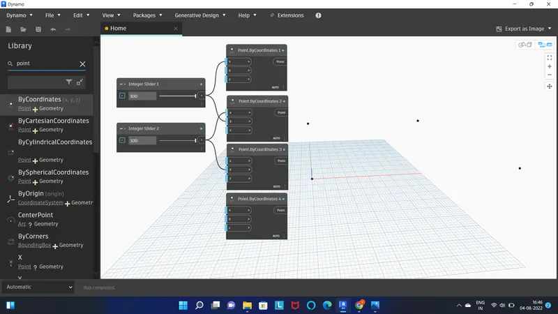
- we got four point
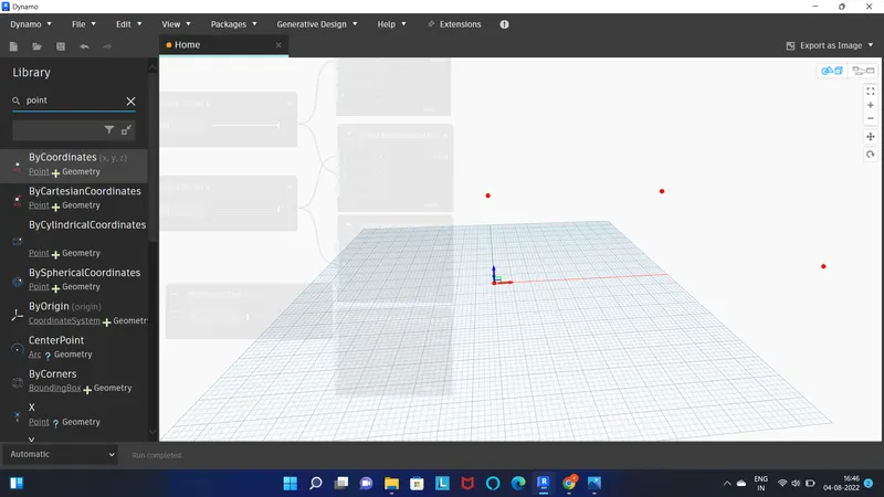
- now we need to make lines
- type line in search box and select line by startpoinr and endpoint
- make 4 box of it
- and connect the point as shown in figure
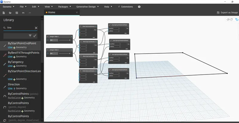
- now we have to create wall height
- type list and select list create
- insert the levels, wall type , integer slider in dynamo workspace
- insert wall by curve and height option
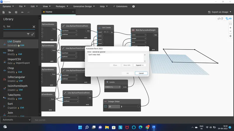
- after following all the prcedure properly error is coming in dynamo in my 2023 version.
RESULT :
we have created conceptual layout of floor plan in dynamo .
3.
AIM :
Create an array of model elements in Revit. Use dynamo to vary the properties of model elements by using the slider or code block
INTRODUCTION :
Dynamo is a visual programming add-in for autodesk revit. dynamo provides open source graphical programming, which enables custom computational design and automation process for building information modelling.
PROCEDURE :
- Open revit
- go to column and make 4 architectural column
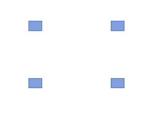
- go to manage tab > select dynamo
- open dynamo and select new page
- now insert the integer slider, select model elements and set rotation by family instance
- go to select model element box > click on select > go to revit select all the column
- type 45 in integer slider box
- connect the model element box to family instance
- connect integer slider to degree of family instance set rotation box
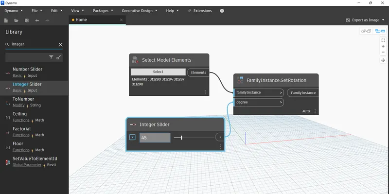
- open the revit and we can see column rotated to 45 degree
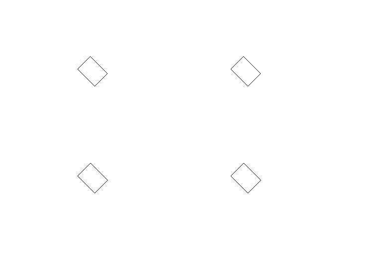
RESULT :
we have Created an array of model elements in Revit. we have Used dynamo to vary the properties of model elements by using the slider or code block
4.
AIM :
Create a conceptual mass in Revit and develop a parametric column by dividing the surfaces and apply the concepts similar to used in parametric walkway modelling. Use triangular bent or square shaped panels to add finish to the parametric column
PROCEDURE :
- Open revit
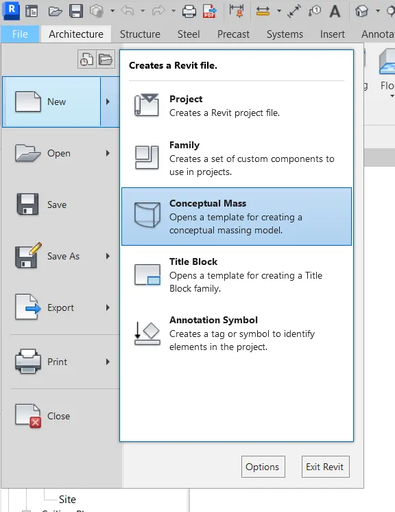
- go to new in file tab > select conceptual mass
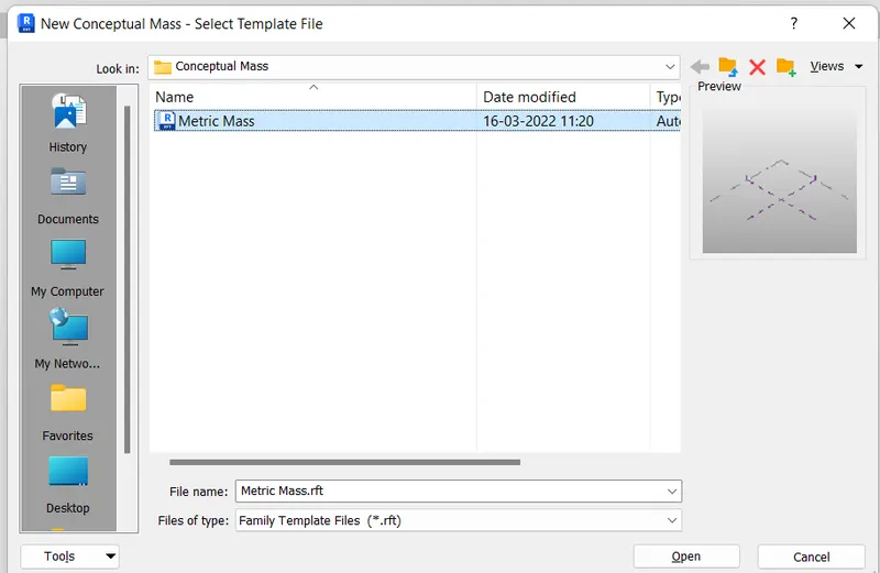
- then select mteric mass and open
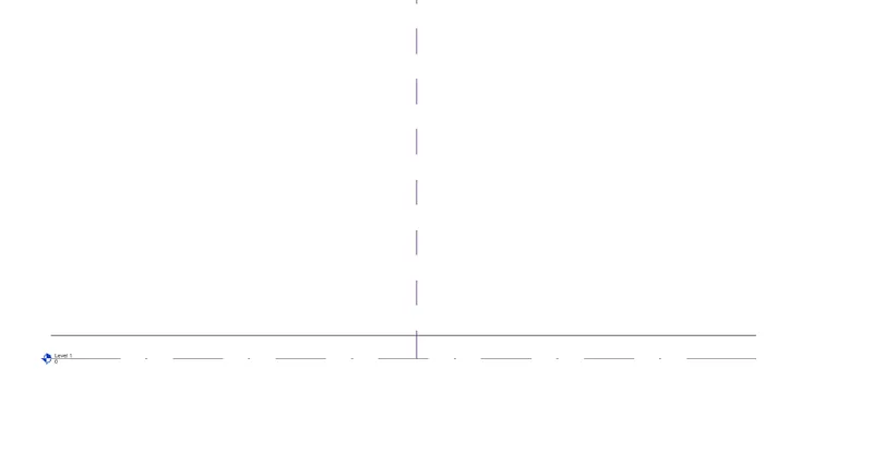
- go to elevation and make level of 12'
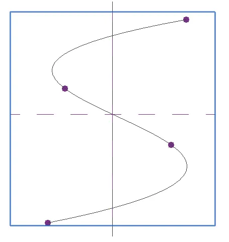
- go to create tab > select model line > select spline command
- make s type shape as shown below
- now we need to set the plane
- go to modify tab select set > select plane
- select the circumscribed polygon give length of 12 feet make on plane we have set
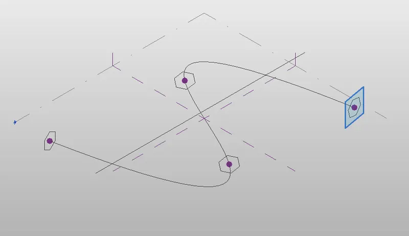
- select the s curve and press control and select the polygon
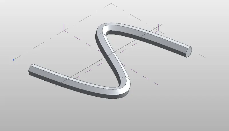
- go to modify tab > select the create form > select solid form
- to make the traingular bent icon
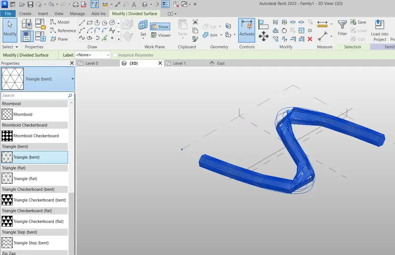
- select whole model
- go to divide surface > in project browser go to pattern
- select traingle bent
RESULT :
we have Created a conceptual mass in Revit and developed a parametric column by dividing the surfaces and applied the concepts similar to used in parametric walkway modelling. we have Used triangular bent to add finish to the parametric column
5.
AIM :
Use Dynamo to work on developing a Parametric Stadium. List your parameters and use the visual programming approach to complete the modelling, You can use the concepts discussed in parametric high rise tower in class for reference.
INTRODUCTION :
Dynamo is a visual programming add-in for autodesk revit. dynamo provides open source graphical programming, which enables custom computational design and automation process for building information modelling.
PROCEDURE :
- open revit and go to manage tab select the dynamo
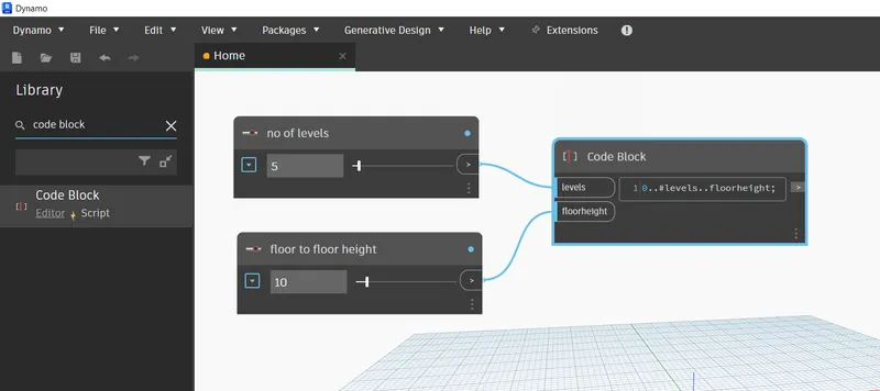
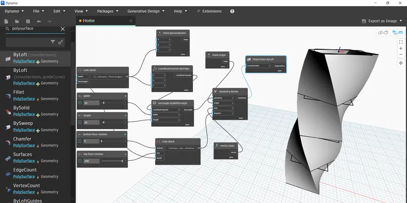
- insert the two integer slider and then code block in screen
- in code block type code 0..#levels..floorheight
- rename the integer slider as floor heights and no of levels
- connect the no of levels to levels in code block
- connect the floor height to floor height of code block
- now we need to mention width and length of building
- insert the 4 integer slider and rename as width, length, top rotation, botoom rotation
- bottom rotation box type 0
- top raotation box type 200
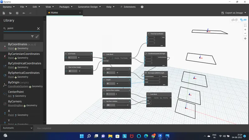
- insert the point by coordinates, coordinate system by origin, rectangle by width.length, and code block
- in code block type bottom..top..#levels.
- connect the above tools as shown in fig
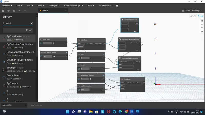
- assign length as 10 and width as 10
- now insert the point origin, geometry rotate, vector.z axis
- connect the point in following way shown in fig.
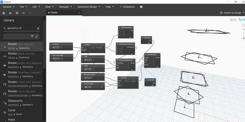
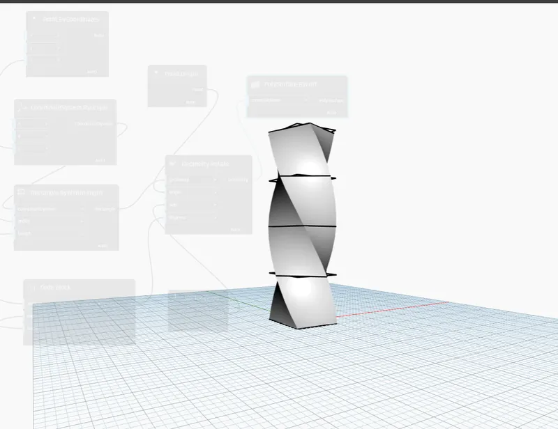
- finally we need to make surface
- insert poly surface by loft
- connect the geometry to surface by loft
RESULT :
we have Used Dynamo to work on developing a Parametric Stadium. Listed our parameters and used the visual programming approach to complete the modelling, we have used the concepts discussed in parametric high rise tower in class for reference.