Creating Conceptual mass in REVIT and Creation of Sinusoidal curve and a Parametric stadium using Dynamo
1. Aim: To create the set of the sinosoidal points and create the curve and to create the surface of the curve using the rivet.
- Dynamo is a visual programming software which helps to cretae the model by expressing the specially arranged graphics or text or along with the both.
- Dynamo not only create the programme but also the dynamo helps the user to create the user or the designer to manuplate the model in the interactive manner.
- The dynamo may also modify the chages in the rivet model which is cretaed by using the dynamo and also the changes are modified very instantly with out any disturbance.
- The model created by the dynamo is very well designed and it satisfy the design requirements also.
- In the dynamo software we will use the various key words like wire,nodes,input,output etc which will help to represent the model in the graphics manner and it also gives the basic information of the model.
- The designer or the building modeler will use this key terminologies for graphically manuplating the input data and after manuplating the data the dynamo exhibits the output data.
- The integer slide or code block are the commands and the integer slider is the command through the input data is entered for the creation of the model.
Procedure:
- Click on the new option and select the architectural template of the model in the file menu click on OK then the file with the architectural template is opened.
- Now open the dynamo in the right side of the window if the dynamo option is not present in the model then we can click the shopping icon and we can downoad and install the dynamo soft ware fro the Auto desk account.
- After the installing the dynamo the file is saved with the appropraite name for further reference and then now click on the dynamo and it may directed to the dynamo page with the rivet page open in the back drop.
- Now the dynamo is linked with the rivet file is ready to create the curve by creating the special arrange ment programme.
- The curve is the set of the points aligned in a lineto create the surface by the visual programming soft ware.
- Enter the integer slider and select the slider icon and the integer slider is displayed in the main window.
- Now select the integer slider aand enter copy(ctrl+c) and pate in the window(ctrl+v) and paste it the slider for the start and step range of the curve also.
- Now enter the start,end and step values for the points of the curve in the integer sliders.This will help to plot the curve with in the range of the start and end with the step interval between the two consecutive points.
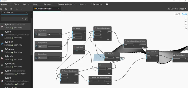
- Now enter the range in the library of the dynamo and select the range with the start,end and step in the range list and te range is displayed in the window.
- Now Input the integer slider values to the range created from the library of the dynamo and assign the integer values as start slide to the start and end slide value to the end and the step also then the set of points are developed from the start range to end range with an interval.
- Now enter the points by coordinate system and select the system iwth the x,y and z axis and assign the range to the points by coordinate system and enter the math sinangle and enter the code block also which will defines the angle of the of the curve points.
- Enter the product and assign the code block angle to the product and the product is asigned to the math sine angle then the curve with the sinusoidal angle is developed.
- Now create the nurbs curve by cordinate and assignth points by coordinates to the nurbs curve and develop the curve path .
- Enter the list in the library and align the nurbs curve option to the item 0 and item 1 in the list and now eneter the surface by loft and asign the list to the surface and it will forms the surface of the sinusoidal curve.
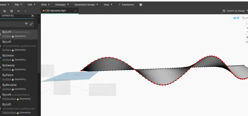
- The final sinusoidal curve developed is as shown below.
2.Aim: To create conceptual lay out of the floor plan and to create the building model elementsoff the curve and to create the surface of the curve using the rivet.
- Dynamo is a visual programming software which helps to cretae the model by expressing the specially arranged graphics or text or along with the both.
- Dynamo not only create the programme but also the dynamo helps the user to create the user or the designer to manuplate the model in the interactive manner.
- The dynamo may also modify the chages in the rivet model which is cretaed by using the dynamo and also the changes are modified very instantly with out any disturbance.
- The model created by the dynamo is very well designed and it satisfy the design requirements also.
- In the dynamo software we will use the various key words like wire,nodes,input,output etc which will help to represent the model in the graphics manner and it also gives the basic information of the model.
- The designer or the building modeler will use this key terminologies for graphically manuplating the input data and after manuplating the data the dynamo exhibits the output data.
- The integer slide or code block are the commands and the integer slider is the command through the input data is entered for the creation of the model.
Procedure:
- Click on the new option and select the architectural template of the model in the file menu click on OK then the file with the architectural template is opened.Now click on the dynamo and the rivet file is linked to the dynamo page
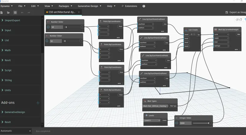
- In the library enter the integer slider and eneter the limit of the coordintes as 50.now create the point by cordinates to four points as the creating model is wall.
- Now asign the intiger slider to the point by coordinates i.e one of the corner is origin and then the remaining forms the corner points of a rectangle shaped wall.
- Now in the library enter the line by start point and end point and enter in the window.Now asign the point by cordinates to these line by start point and end point then the outer edge of the walls are formed.
- Now enter the list create in the search bar or in the family and and create the list as item0,item1,item2,item3.
- Now the final step the wall is to enter the parametric changes or properties of the wlall.Now enter the wall by curve height in the library and and asign thelist created previously and it forms the wall with the various parametric changes like curve,height,level and wall type.
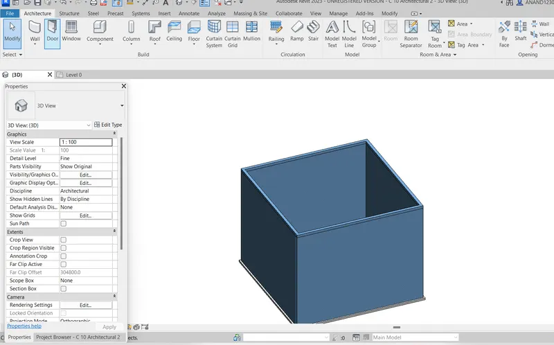
- After asigning the wall by curve height the wall is formed around with the certain thickness aroundthe layout.
- The final result for the layout of the wall is formed as shown below.
3.Aim: To create the array of the model elements in the dynamo using the rivet soft ware.
- Array is the tool which isused for the set of building elements like beams,columns and other units to roate about an axis or about an angle with out any change of the oarameters of the building elements.
- In the process of cretaion of the building modle some times the positionnor orientation of the building models is tobe changed and at that it may take long time to change the position or orientation of the units individually at that time we can use the array option in the dynamo to change the position or orientation of the model elements of the building.
Procedure:
- Click on the new option and select the architectural template of the model in the file menu click on OK then the file with the architectural template is opened.
- Select the column or the beam in the ribbon and plot the column or the beam with the rquired size in the window.now the model is created with the various column positioned at the different places.
- Now click on the mange icon and select the dynamo and the rivet is directedc into the dynamo page and save the project in the dynamo for the future reference.
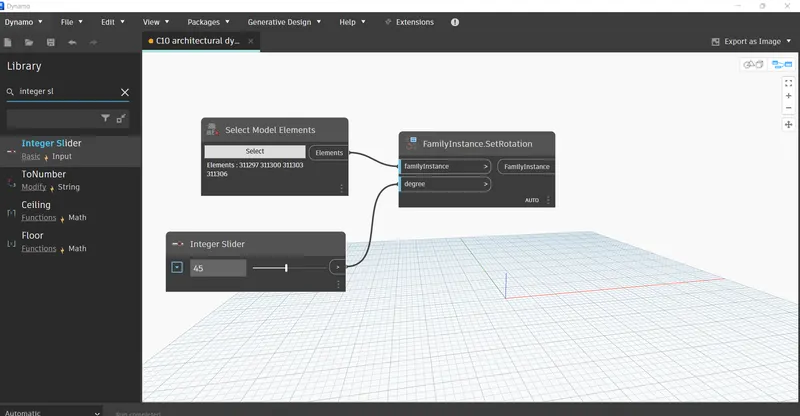
- Enter the model elements in the libraray of the dynamo and select the slect model elements in the library then the icon is displyed in the window.
- Now enter the rotation in the library of the dynamo and select the family instance set rotation and also create the integer slider which will define the rotation angle of the building unit like columns or beams doors or windows or any other units.
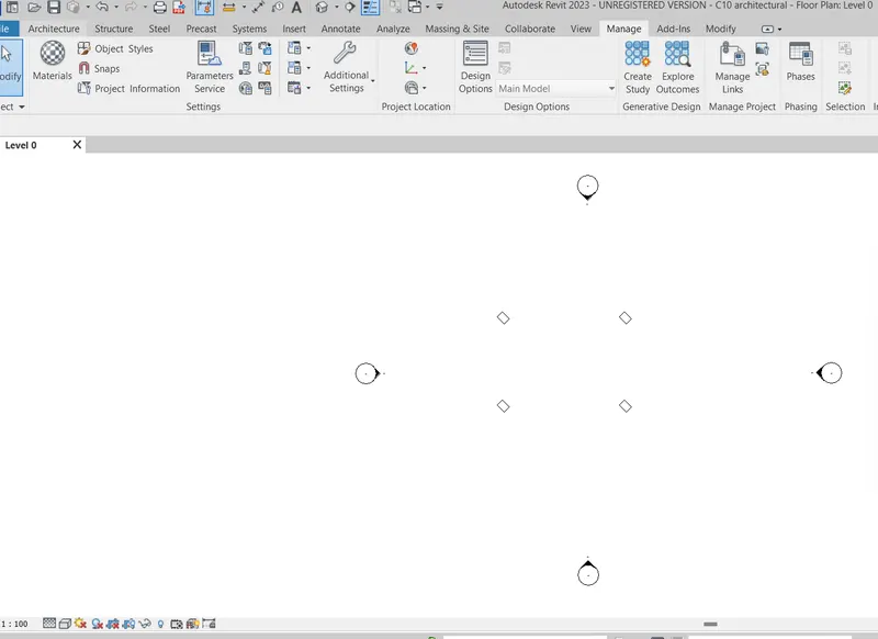
- Now click on the select icon in the select model elements and open the rivet page and select the building units which are to be position changed then all the selected building elemenst are linked in the dynamo and now enter the angle in which the building units are oriented and asign the icon to the family selection set rotation.so the building models units are oriented in the rivet window.
- Now the final result of the building units formed are as shown below.
4.Aim: To create the conceptual mass of the building unit and to develop the parametric surface of the building units using the rivet soft ware.
- Conceptual mass is nothing but the model of the building developed by the sold mass of the material and it is developed to know the solid range of the model in the real life.
- Coceptual mass is one of the best tool which will help to create the solid models with out any deviations
Procedure:
- Click on the new option and select the architectural template of the model in the file menu click on OK then the file with the architectural template is opened.
- Click on the file and select the new icon and select the conceptual mass tremplate of the model then model is directed to the metric mass and now select the metric mass in the model.
- Now click on the elevation and create the another level at a particualr distance away from the level 0.
- Now click on the create icon in the ribbon and select the require building unit which may be column or select the drawing shape which is in the ribbon.
- Now select the rectangle icon and plot the rectangle in the window and the rectangle is plotted by the required size.
- Click on the set option and slect the corner edge of the rectangular model,click on all the four edges of the building and assign the shape.The assigned rectangular shape is to be visualised and again if they are not visualized then the click on the show icon the ribbon.
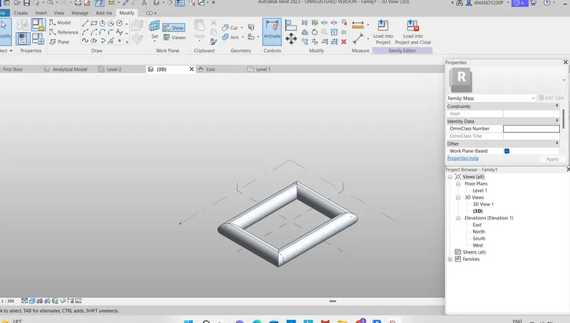
- Click on the model created and select the model and then select the create the solid form option in the ribbon then the conceptual mass of the model is formed.
- The result conceptual mass of the project is formed as shown below.
5.Aim: To create the parametric stadium and to list the parameters using the visual programming and to create the surface using the rivet.
- Dynamo is a visual programming software which helps to cretae the model by expressing the specially arranged graphics or text or along with the both.
- Dynamo not only create the programme but also the dynamo helps the user to create the user or the designer to manuplate the model in the interactive manner.
- The dynamo may also modify the chages in the rivet model which is cretaed by using the dynamo and also the changes are modified very instantly with out any disturbance.
- The model created by the dynamo is very well designed and it satisfy the design requirements also.
- In the dynamo software we will use the various key words like wire,nodes,input,output etc which will help to represent the model in the graphics manner and it also gives the basic information of the model.
- The designer or the building modeler will use this key terminologies for graphically manuplating the input data and after manuplating the data the dynamo exhibits the output data.
- The integer slide or code block are the commands and the integer slider is the command through the input data is entered for the creation of the model.
Procedure:
- Click on the new option and select the architectural template of the model in the file menu click on OK then the file with the architectural template is opened.Now click on the dynamo and the rivet file is linked to the dynamo page
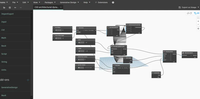
- To create the parametric stadium with the top angle of rotation.enter the integer slider in the library and edit the sliders as the number of levels (5) and the other integer slider as floor to floor height (12').
- Create the code in the cde block between the level and the number of floors (0..#levels..floor height;) and now assign the previous integer slides to the code block after cretaing the code only.
- Create the integer slides and edit the titles as width, length,Bottom rotation and top rotation and also create the point by cordinate and point by origin system.
- Assign the code block for the levels and the floor height to the point by coordinate system.
- Now eneter the rectangle for width, length from the library and align the integer slides of the rectangle and the rectangle will be formed.
- Click on the point by coordinates and assign the point from the code block then all the points are assigned with the point with the with the origin.
- Now create the code block and create the code 1..levels and the rotation angle with top and bottom of the building.
- Select the geometry rotate and surface loft and the geometry rotate is loaded from the library and the all the levels the assigned are associated with rotate icon and after the modle is aligned with the surface loft.
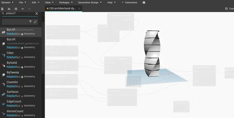
- The final result of the project with the certain rotation at the top of the building is obtained as below.