Creating Conceptual mass in REVIT and Creation of Sinusoidal curve and a Parametric stadium using Dynamo
 1.Using Dynamo create a set of sinusoidal points and create a curve and create a surface out of the curve.
ANS:Tools used:
1. Manage.
2.Dynamo block.
3.Code Block.
4.math.sin
5.integer slider.
6.add
7point by co-ordinate.
8.Surface lost
Procedure: open the revit and select the new template.
save the file
go to manage tab and select dynamo.
The dynamo work space will open and click on new and now we start in dynamo.
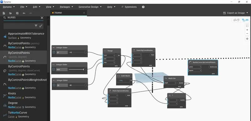
First to draw a sunsoidal curve we need certain parameters like start, end step,we can get by selcting the 3code blocks from the library and rename them.
Now select the range and by coordinates from library.
Connect the start, mid and end range and range to the point by coordinate.
select the math.sin parameter to draw the sin curve and connect the node to range.
select toadd parameters and remname the operators.
select the number of sliders and connect to the origin point and also connect end point.
select the code and rename it as amplitude and connect it to the amplitude.
select the number slider and name it as phase and connect it to the phase.
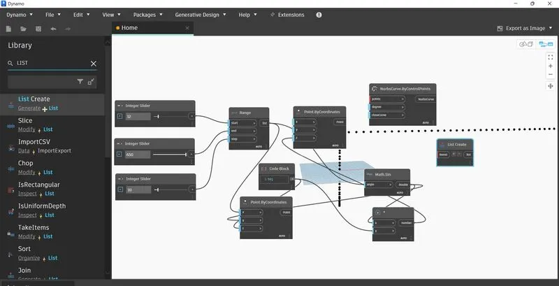
select thr nurbscurve by co-ordinates join it to point by co-ordinates.
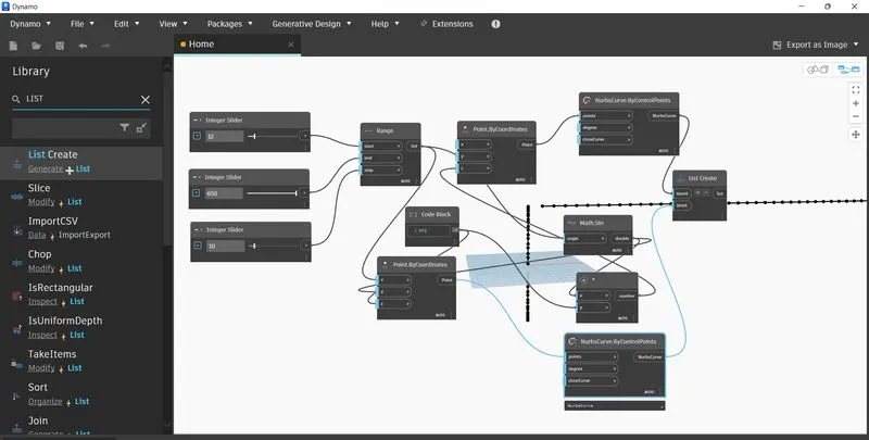
select the all nodes and go to the edit and select the create node from seection.
sign curve with inputs will appear copy the sign curve and connect them.
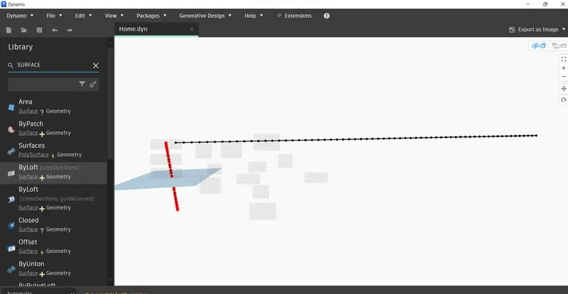
select the list create and connect each item to each sign curve.Select the surrface loft.
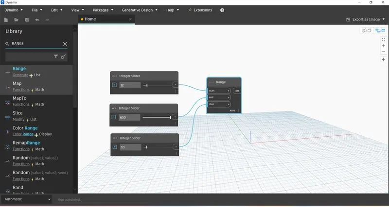
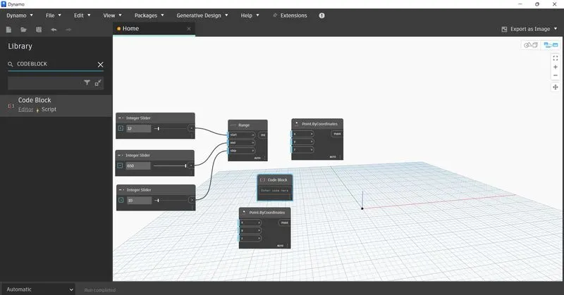
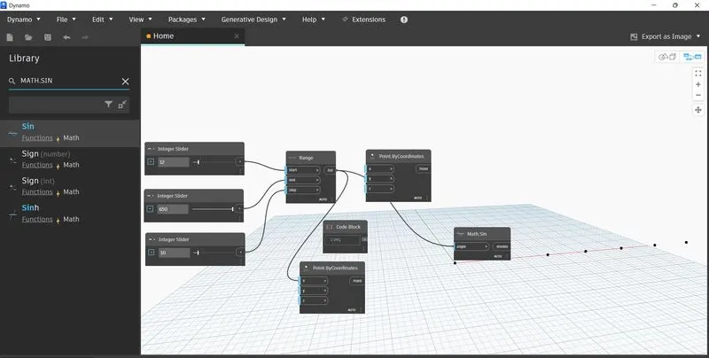
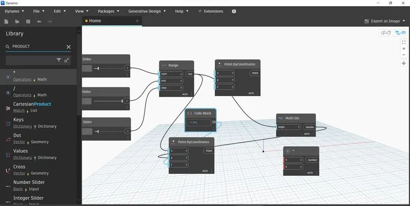
2) Create a conceptual layout of floor plan in dynamo . Using the tools available in dynamo link the lines to appropriate model elements in Revit by choosing the wall types and wall parameters. Make use of the sliders to slide through the height of the wall and length of the wall.
ANS: Tools used:
1.Dynamo
2. code block.
3. point by co-ordinate.
4.integer slider.
5. wall types
6. levels
7. wall by curve and height.
Procedure: open architectural template in revit.
go to manage tab and opn dynamo
The dynamo work space is created. create a new window.
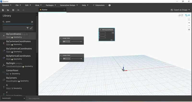
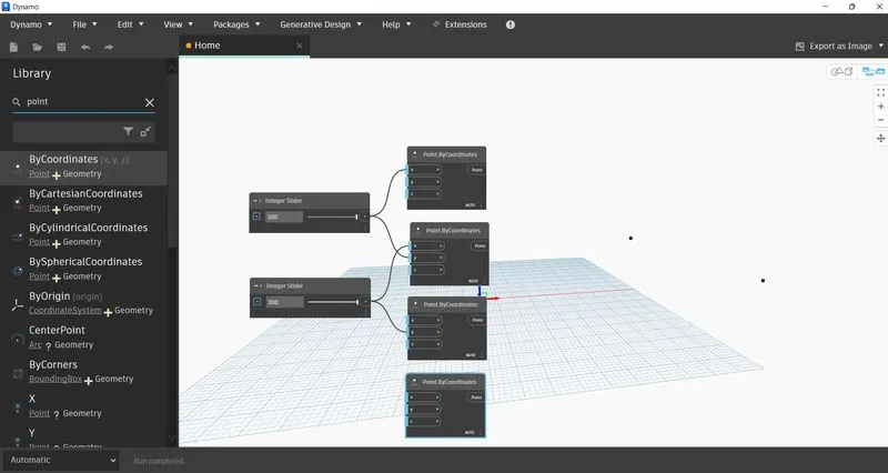
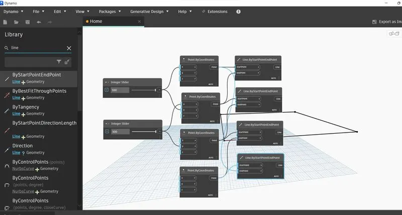
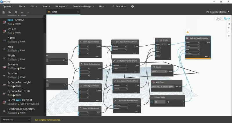
create four control point by selecting by co-ordinates from library.
rename the coordinates as origin (0,0,0) cntrl point 1(x,0,0) contrl point 2(0,y,0) cntrl point 3(x,y,0).
Now create two number slided and rename them as x& y.
The x- parameter cant be 0 as assigned as 10 and set up as 1.
then connect the nodes of x to the control point 1 and control point 2.
then connect the y to the control point 2 & 3.
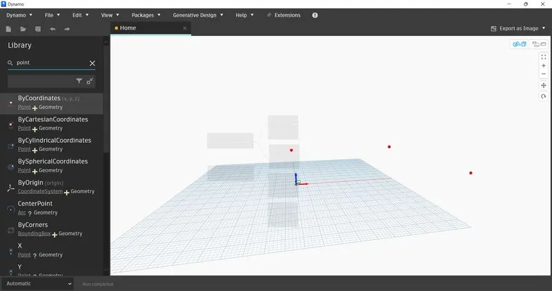
Now go bavck to the modeling space we can seal all the points.
next function is line by start point and end point select 4 lines.
The first line is between (0,0,0) & (x,0,0).
the second line is going between (0,y,0) and (x,y,0)
The node end point of first line is connected to the start point of second line.
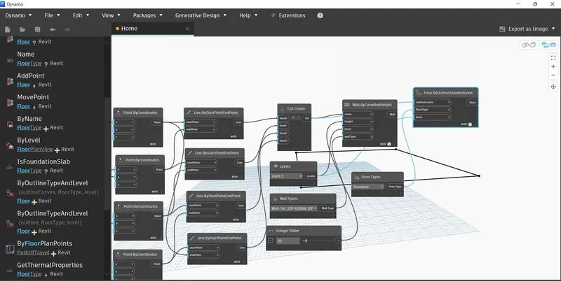
select wallby curve and height and assign input parameter by selecting wall types, level, numbersliders and name as height of wall.
select the list and create and join all the lines to it.
now assign all the parameters to wall; by curve and height.
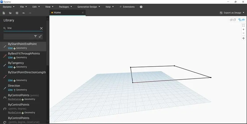
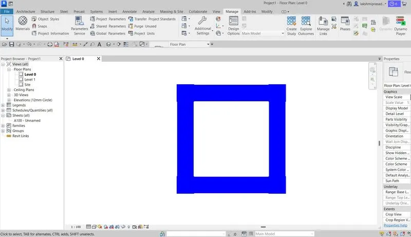
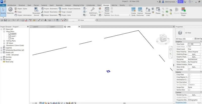
go to view window and viwew it in revit.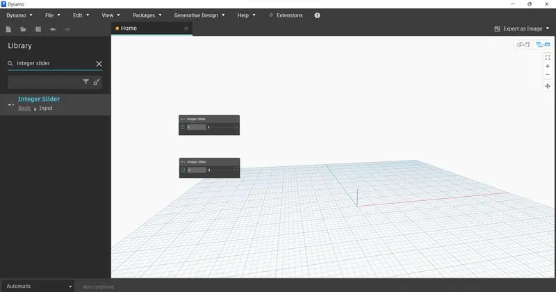
ANS:Tools used:
1.Family
2.reference plane
3.generic model.
4.extrusion
5.void form
6.label
7.save
procedure: Open revit model.
select generic model click ok open.
select create and click on reference plane and create reference plane as offset.
next select the extrusion and click on curves and pick lines to draw the model cklick ok.
allign the referances to the palne of our model.
allign the dimensions and save it.
go to file and families and selec the generic model family based.
create a array at the model and draw a offset.
add the labels and rename them.
3.)Create an array of model elements in Revit. Use dynamo to vary the properties of model elements by using the slider or code block
Tools used:
Architeture template.
columns
dynamo.
integer block.
select model elements.
code block
view
set rotation.
procedure: open arc tem in revit software.
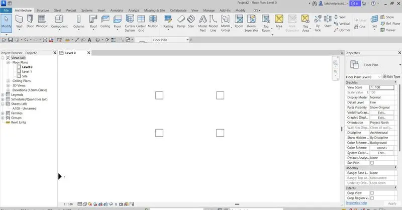
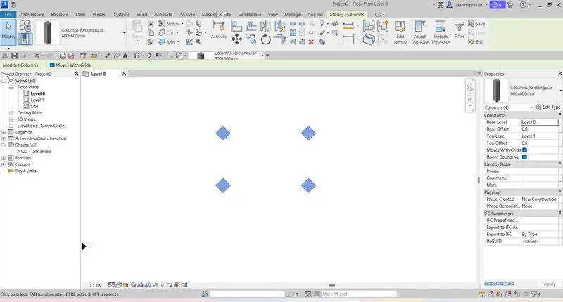
select the column in the architect tab and draw the columns.
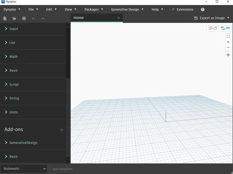
then go to manage tab and selec the dynamo.
go to new now the new works plane is created.
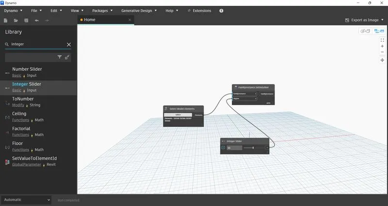
go to the libraries and search the selct model and elements and now click on select and go to revit and select the columns.
add the set rotation , code blocck and number slider parameter.
give the standard value to the code block and connect & select model elements.
now connect the integer slider to set rotation of columns.
now by changing the integer we can see the changes in the revit simultaneously
4) Create a conceptual mass in Revit and develop a parametric column by dividing the surfaces and apply the concepts similar to used in parametric walkway modelling. Use triangular bent or square shaped panels to add finish to the parametric column
TOOLS USED:
Familiars.
new conceptual
level
line
refernce point
divide surface
create from
filter.
Proceudure:
open the revit .
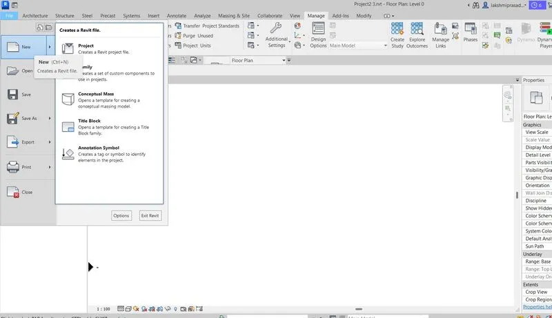
click on new families and dialogue box apperas selction the conceptual, mass click open.
next the conceptual mass workspace open.
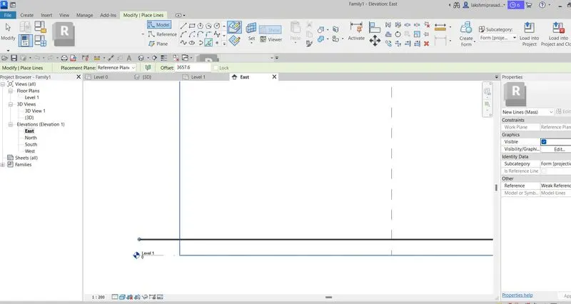
now go to any of the elevation view and draw the level at on offset of 10'.
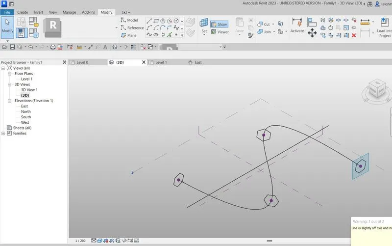
now selec the line and draw the line and put the reference point on the line at appropriate distances.
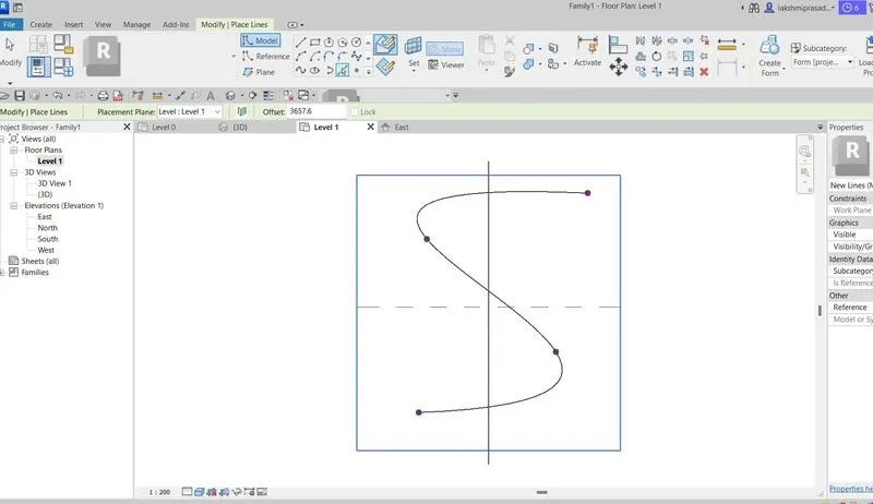
now go the 3d view and inscibed the poly gon theme.
select the components and click on the create form.
select the elements and click on the divide surface tool.
now go to file >new>families & select the curtain panel pattern based and click ok.
here we can create our won pattern and save them time load them in to the project.
tomake column i have selcted triangle bend,
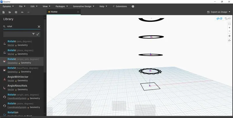
5) Use Dynamo to work on developing a Parametric Stadium. List your parameters and use the visual programming approach to complete the modelling, You can use the concepts discussed in parametric high rise tower in class for reference
ANS: TOOLS USED:
Dynamo
integer slider
code block
coordinate system by origin
rectangle by width and length.
procedure:
open the revit annd create a architecture template.
go to manage tool and click on dynamo
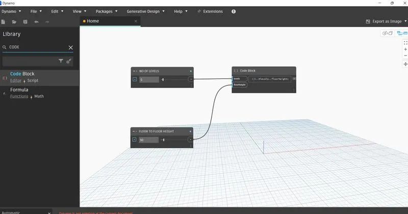
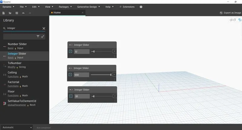
create a new work space and go to library and selct the four integer slider and assign them as number of levels floor to floor , bottom floor ,top floor rotation.
create a code block and added the parameters levels , floor,height and connect them.
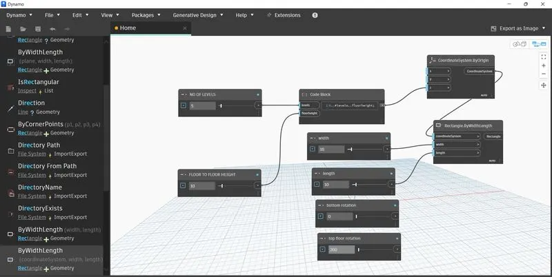
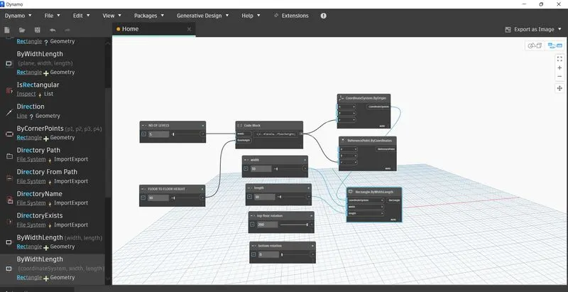
added by coordinates by origin rectangle by width length. and integer slider rename it added with# length of rectangle.
connected the width #length of rec to width and length in the rec by width lenght and connnect coordinates of origin to the code block.
connect the nodeof co-ordine system by using to CS of rec bywidth length.
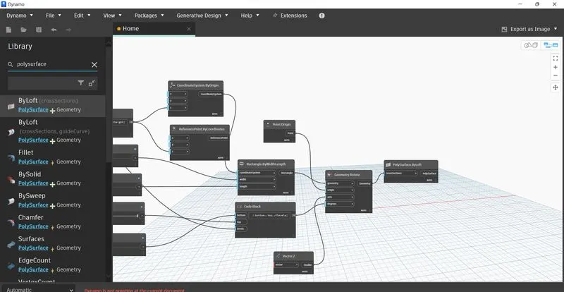
create a point design & vector, z-axis & geometry rotate and a code block.
connect the nodes of point origin and vector z-axis to the origin and access in the geomentry rotate parameter.
create a code block for bottom,top & levels& connect them and connect the nodes of code block to degree of geometry rotate.
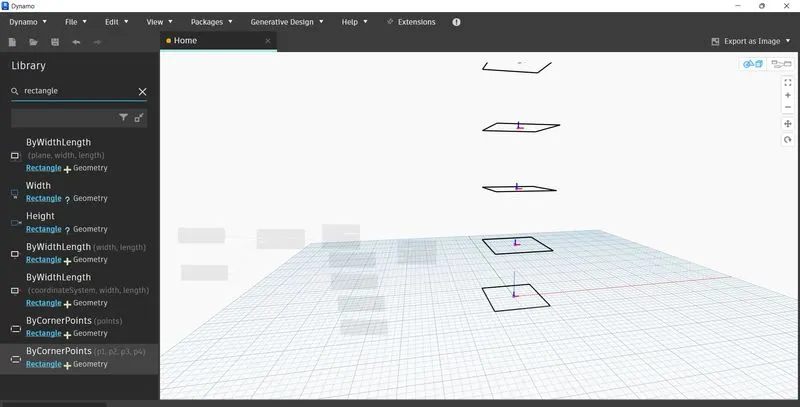
create polysurface by loft and connect the nodes of geometry rotate to it.
now change the parameter slike number of levels, floor height,and view the changes in the model.
we can also change the width and length of th model and angle of rotation of both top & bottom.