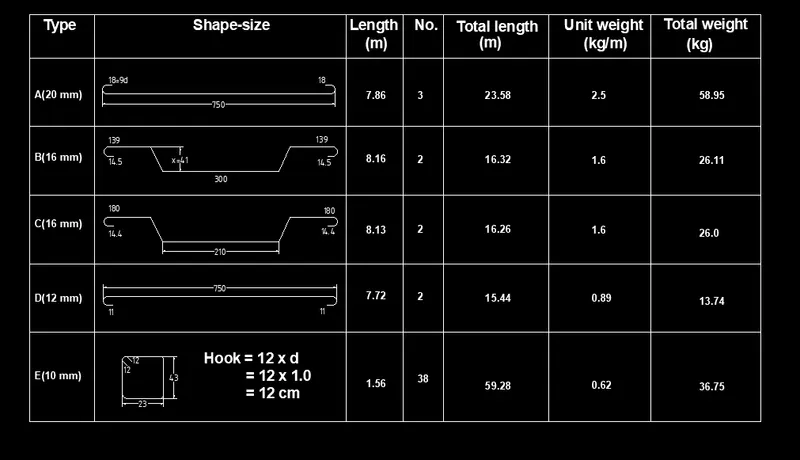
Creating Bar Bending schedule, Different Door types, and Creation of standard drawing templates using AutoCad
Q-1
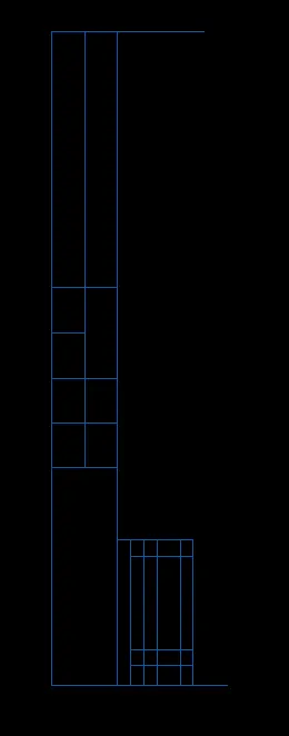
Create the templates as shown in Figures. Take the size of the title block as per industry standards or you can assume it as per the size of the paper. Use text and attributes wherever required. After creating the title block you need to save it as a block with names: Custom1_titleblock and Custom2_titleblock, respectively.
AIM-TO CREAT TEMPLATES AS THEY GIVEN IN FIGURE AND CONVERT THEM TO BLOCK .
COMMAND USED IN FIGURE :-
- LINE
- OFFSET
- TRIM
- BLOCK
- TEXT
PROSEDURE FOR TABLE 1 :-
- first open autocad setl imits and units.
- now take line command and draw one rectangular box as they given in figure.
- assume the dimension for box.
- now use offset and line command and make every box and lines in the rectangular box.
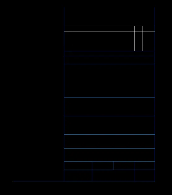
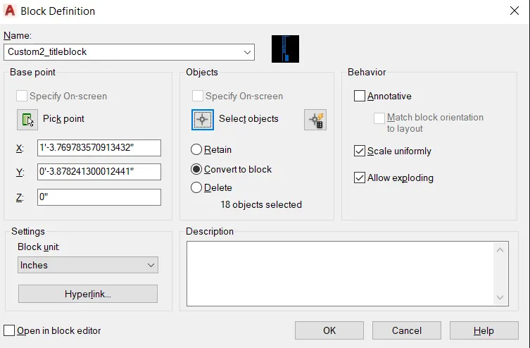
- now we have to convert this box into the block.
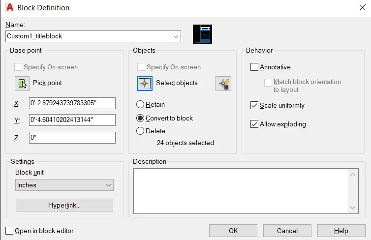
- type b for block command.
- give name to block - Custom1_titleblock.
- select whole box nd convert into the block.
- now using the text command write every text in the box.
- select proper dimension style and size.
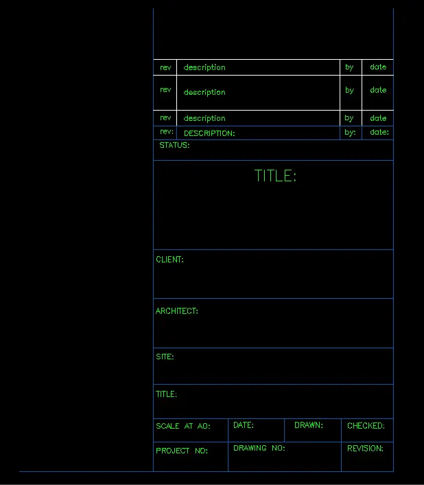
PROSEDURE FOR TABLE :-2
- same as above table draw the box using line command.
- using offset command drawevery part as they shown in figure.
- assume the dimension to draw box.
- now same as 1st table we have to convert this into the block.
- using b for block command we can convert to block.
- select the whole box and give the name -Custom2_titleblock.
- now using the text command write every text in the box.
- select proper dimension style and size.
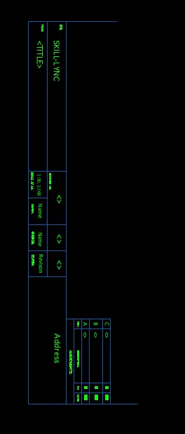
RESULT :- BOTH TABELS ARE DRAWEN IN AUTOCAD.
QUE-2
Create the doors type for warehouse as shown in the Figure. You need to create each door type as per
standard size or given dimensions. Create the blocks of this door type after creating them.
AIM-TO CREATE THE DOOR TYPES FOR WAREHOUSE AND CONVERT THEM TO BLOCK.
COMMAND USED IN THIS DRAWING :-
- offset
- copy
- move
- mirrior
- trim
- block
- rectangular
- dimension tool
PROSEDURE FOR DOOR 1
- first open autocad set units to mm.
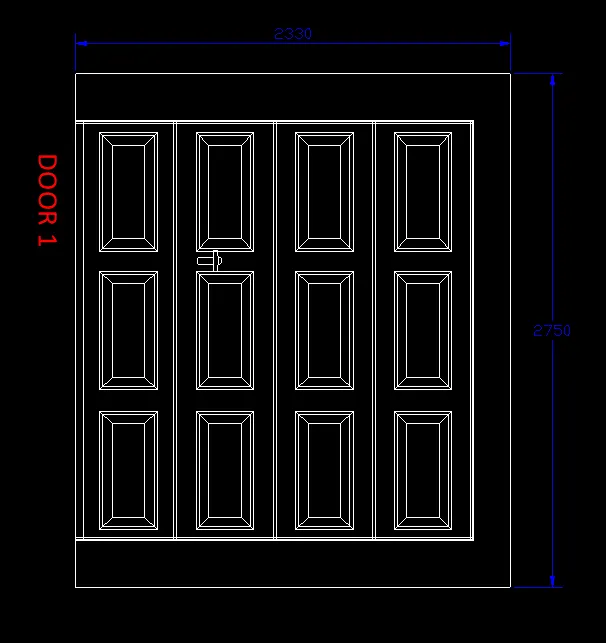
- take line command draw horizontal line of 2330 draw onther ine to the downword with lenght of 2750.
- draw onther line of 2330 to the back side nd complate the box.
- now take offset command give offset of 150 to the upper and lower both side.
- to the right side give offset of 100. in the middle box give divid command and make 4 part .
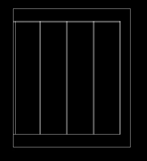
- now we have to create inner doors and convert them to block.
- give name to the block - door1
- for size we can assume the dimension.
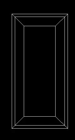
- now put this all doors into the first figure as they shown in figure.
- give the dimension .
PROSEDURE FOR DOOR 2
- for door to we have to follow same method as door 1
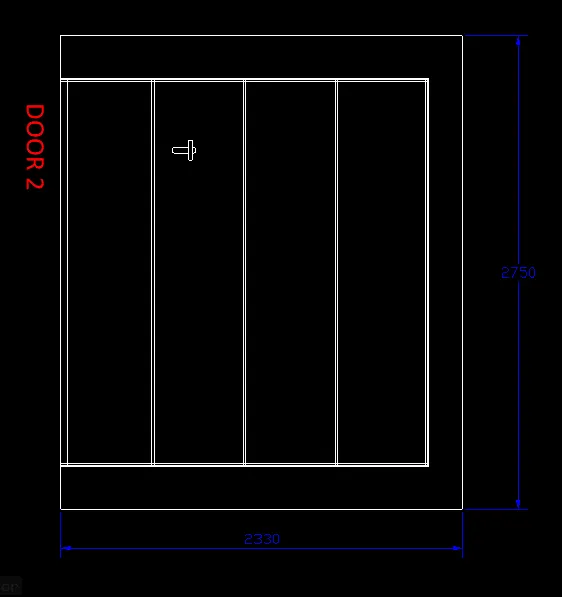
- take line command draw horizontal line of 2330 draw onther ine to the downword with lenght of 2750.
- draw onther line of 2330 to the back side nd complate the box.
- now take offset command give offset of 150 to the upper and lower both side.
- to the right side give offset of 100. in the middle box give divid command and make 4 part .
- convert them to block and give name - door2
- give the dimension .
RESULT :- BOTH DOORS ARE DRAWEN IN AUTOCAD.
QUE-3
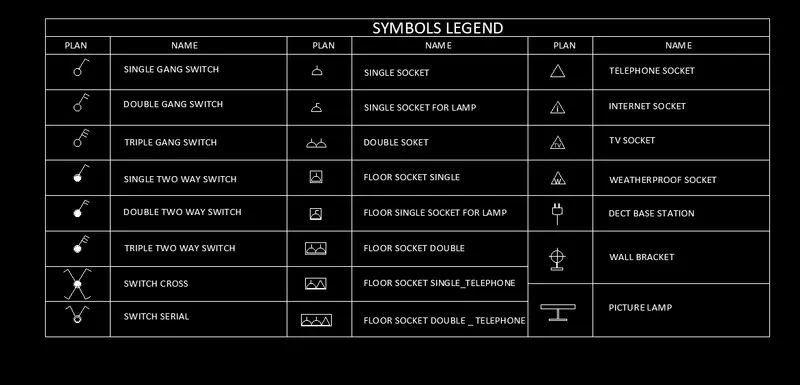
Create each symbol as a block with the name given in the legend. After creating the blocks arrange
them in the legend as shown in the Figure.
AIM :- CREATE EVERY SYMBOL THEN CONVERT THEM TO BLOCK AND ARRANGE THEM IN ORDER.
COMMAND USED IN FIGURE :-
- line
- circle
- block
- offset
- text
PROSEDURE FOR DRAWING :-
- first opem autocad and set the limits.
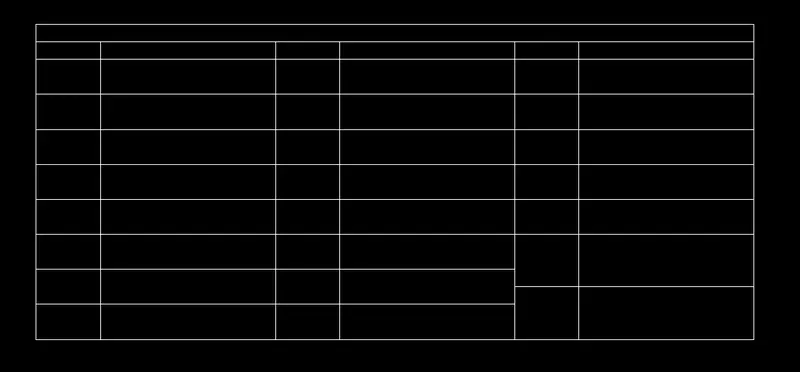
- first we draw table using line command as per reqirement.
- we draw all parts in table as they shown in figure .
- now its time for symbols .
- we can draw symbols using line,circlr and arch.

- now convert this symbol to the block same as we done in figure 1 and give the name as they given in drawing.
- now draw second symbol same as firstone and also convert them to block.

- same as above method we have to draw all symbols and convert them to block .
- after that put every sumbol at their places and fill the reqired data in table using text command.
QUE - 4
Create the door type for residential building as a block. Save the name of the blocks as type. Use given
dimensions or assume dimensions as per industry standards.
AIM:- TO CREATE THE DIFERENT DOOR TYPES FOR RESIDENTIAL BUILDING AND SAVE THEM TO THE BLOCK.
COMMAND USED IN FIGURE :-
- line
- offset
- block
- dimension tool
- limits
- unit
- dimsy
- style
- text
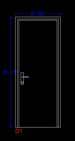
PROSEDURE FOR DOOR 1 (D1) :-
- first open autocad set units to the engineering give precision to 0'0" .
- now take line command draw horizontal line of 2'10" .
- now draw vertical line from last point of 6'11" .
- again draw horizontal line of 2'10" .
- give offset of 2 to 5 inches to all side.
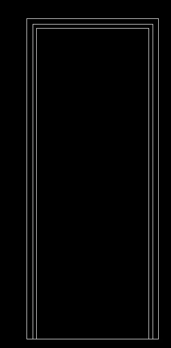
- now use dimension tool and give the dimension.
- after creation of door convert them to block and give name D1 .
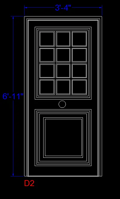
PROSEDURE FOR DOOR 2 (D2) :-
- same as d1 we have to draw a box using line command .
- dimension are 3'4" x 6'11" .
- give offset to them by assuming the dimension.
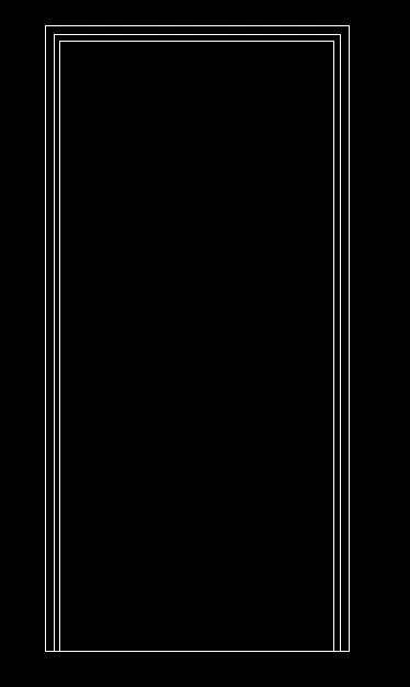
- now we have to give just offset inside the door and create two rectangular box inside the door .
- assume the dimension for offset .
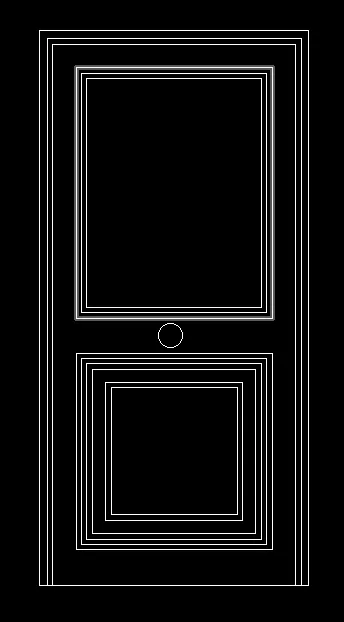
- after that we have to draw small rectangular parts in the box shown in figure.
- assume the dimension for small rectangular box.
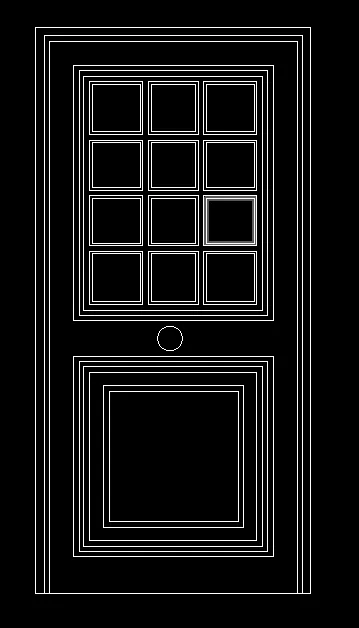
- after the creation of this door convert it into the block same as we did it before and give name of D2 .
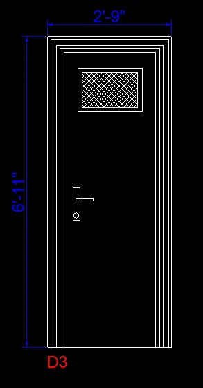
PROSEDURE FOR DOOR 3 (D3) :-
- same as d2 we have to draw a box using line command .
- dimension are 2'9" x 6'11" .
- give offset to them by assuming the dimension.
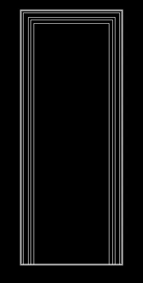
- after that draw one rectangular box on the upper side of door .
- after the creation of this door convert it into the block same as we did it before and give name of D3 .
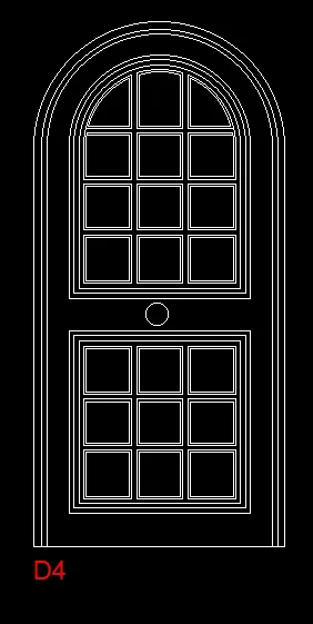
PROSEDURE FOR DOOR 4 (D4) :-
- same as d3 we have to draw a box using line command .
- dimension are 2'9" x 6'11" .
- give offset to them by assuming the dimension.
- now take arc command and draw one arc on the upper side of door .
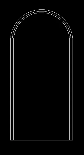
- now take line or rectangular command and draw two rectangular box inside the door .
- same as first step draw arc on the upper rectangular .
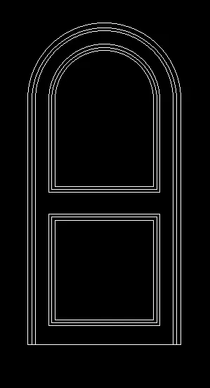
- now same as 2nd and 3rd door we have to create small rectangular boxes in the dooe and after that convert this door into the block give name D4.
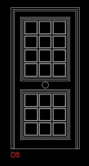
PROSEDURE FOR DOOR 5 (D5) :-
- same as d3 we have to draw a box using line command .
- dimension are 2'9" x 6'11" .
- give offset to them by assuming the dimension.
- now draw tow rectangular box inside the door by assuming the dimension .
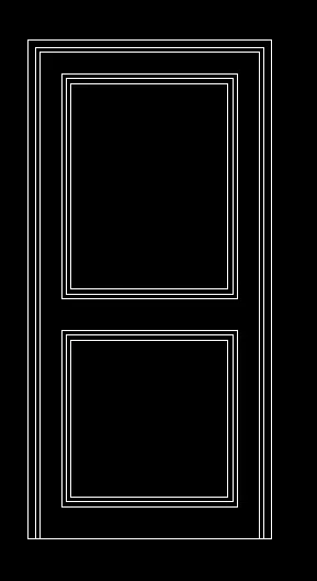
- same as D4 method create rectangular box and put them inside the door as they shown in figure.
- after the complition of door convert it into the block and give name D5.
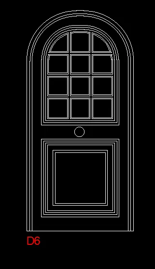
PROSEDURE FOR DOOR 6 (D6) :-
- to create door 6 follow the prosedure of door 4 and convert into the block.
RESULT :- ALL DOORS DRAWING DRAWEN IN AUTO CAD.
QUE - 5
Create each shape as a block as shown in the Figure. Save the block and insert them on the table as shown in the Figure.
AIM :- CREATE SHAPES AND CONERT THEM TO BLOCK AND INSERT INTO THE TABLE.
COMMAND USED IN THIS DRAWING :-
- line
- offset
- divid
- block
- insert
- text
PROSEDURE FOR DRAWING :-
- first open autocad set units and limits .
- after that we have to create one box as they given in figure.
- after creating box convert into the block using block command .
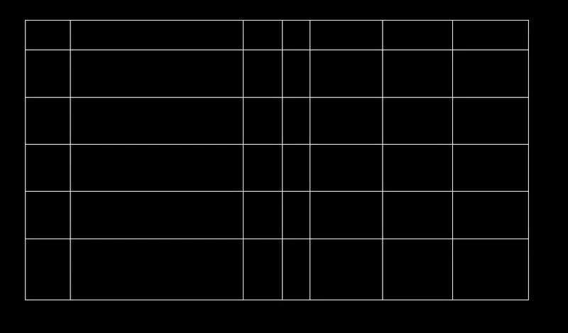
- after creating box we have to draw each shape as per dimension and convert each shape to the block.

- after the creation of every part convert them to block .
- put every shape in the box as per reqired.
- using text command give text to every shape and write down the all data .