Creating Bar Bending schedule, Different Door types, and Creation of standard drawing templates using AutoCad
QUESTION NO. -1
ANSWER:
AIM: Create the templates as shown in Figures. Take the size of the title block as per industry standards or you can assume it as per the size of the paper. Use text and attributes wherever required. After creating the title block you need to save it as a block with names: Custom1_titleblock and Custom2_titleblock, respectively.
INTRODUCTION: FOR START THIS DRAWING FIRST OF ALL WE HAVE TO DO SOME SETTINGS ACCORDING THE DRAWING -
DRAWING LINK
https://web.autocad.com/acad/me/sid/shares/drawings/177fd18b-3665-49c9-957a-b0bee098a586/editor
SOFTWARE SETTINGS
SETTINGS - OPEN AUTOCAD
- SET DEFAULT SETTINGS - METRIC UNIT (mm)
- SELECT A TEMPLATE - ACCORDING TO DRAWINGS
- SELECT A WIZAED - ADVANCED SETUP
- UNITS - DECIMAL
- ANGLE - DECIMAL DEGREES
- ANGLE MEASURE - ACCORDING TO PLAN
- ANGLE DIRECTION - COUNTER CLOCKWISE
- AREA - ACCORDING TO PLAN
After this enter "D" for dimetion unit and set primary unit DECIMAL set precision 0
MODES -
- GRID ON BY F7 'CONTROL+G'
- USE ORTHO MODE FOR STRAIGHT 90 DEGREE ACCRDING NEED(F8)
- ON POLAR TRACKING (F10) SET ANGLE (15,30,45)
- OBJET SNAP TRACKING (F11)
- OBJECT SNAP (F3)
- TRANPARANCY ON WHEN YOU NEED
PROCEDURE:
For Custom1_titleclock ,drawing:
STEP-1
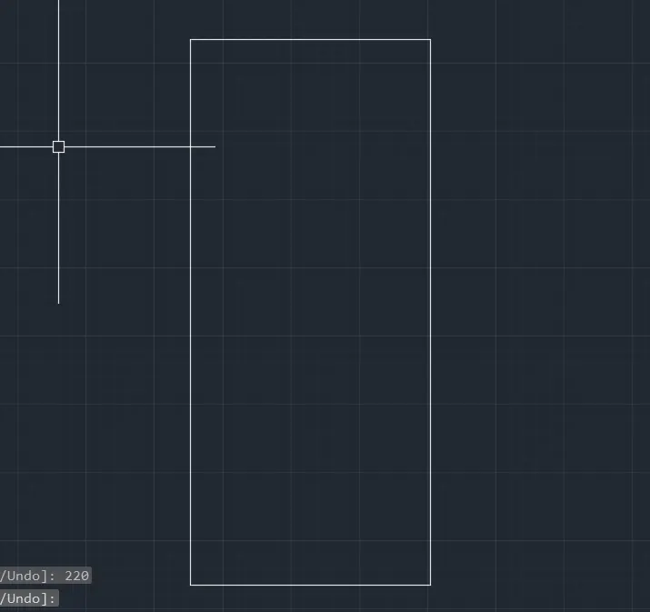
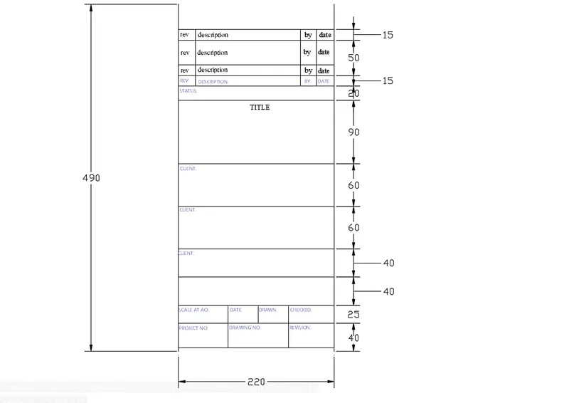
- Creat a rectangle with the help of rec command.
- put the width of the rectangle is 220 mm and hieght of the rectangle is 500 mm
STEP-2
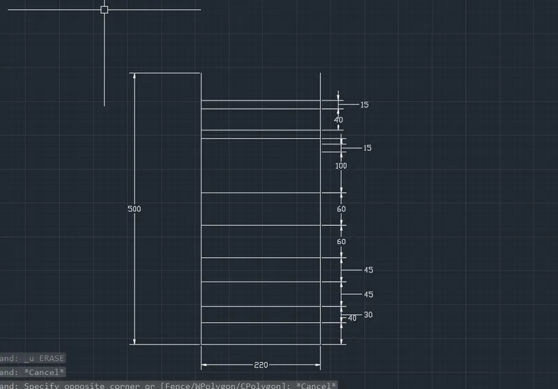
- Now with the help of offsett command take offset 40mm upward direction.
- Again take offset 40mm from last offset
- Again take offset 30mm from last offset
- Again take offset 45mm from last offset
- Again take offset 45mm from last offset
- Again take offset 60mm from last offset
- Again take offset 60mm from last offset
- Again take offset 100mm from last offset
- Again take offset 15mm from last offset
- Again take offset 40mm from last offset
- Again take offset 15mm from last offset
STEP-3
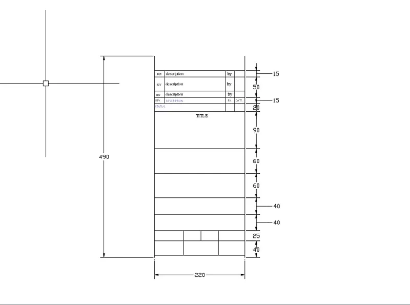
- Go to mtext command and start writing written content.
- go to height of text and upper heading write with color of and and put blue in the bottom box and line.
STEP-4
- write description , site , date , rev, client , tiltle etc in the different boxes.
- with the dimention command measure all the dimentions.
- set line weight .19 for bottom and side .
STEP-5
CREAT BLOCK
- Now go to the final part o the drawing
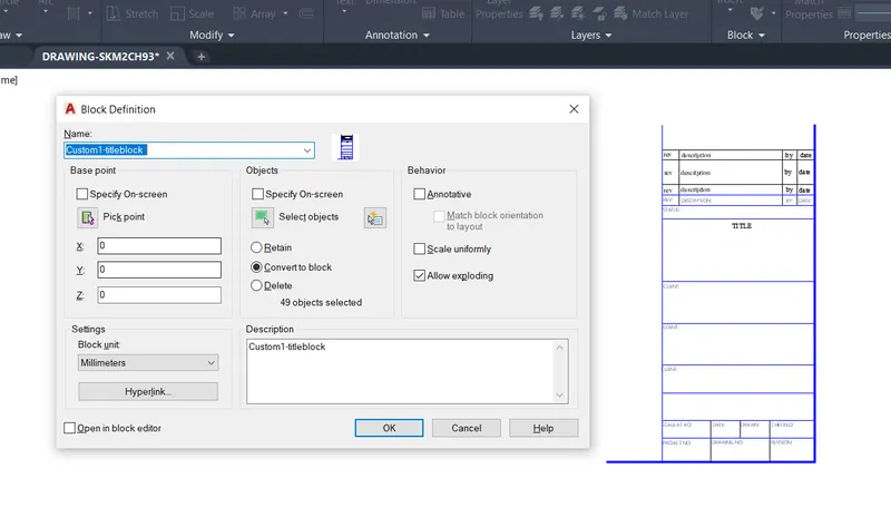
- select all the autocad drawing object than enter block command in the command bar.
- Now put the name Custom1_titleclock in the name box
- pik up point of this object
- than go to description part and describe about this
- now press okk
- this object is converted in to the block.
STEP-6
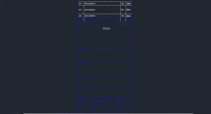
Autocad black screen drawing
STEP-7
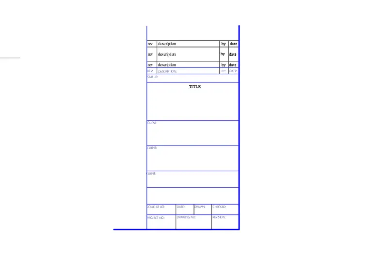
White layout drawing:
Custom2_titleclock ,drawing:
STEP-1
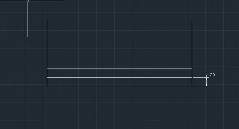
- To draw this drawing go to line command and take a horizontal line.
- Now take offset of 30mm from horizontal to upward direction.
- again take offsett of 30 mm.
- draw a vertical line and take offset 575 from vertical line to the +X direction
STEP-2
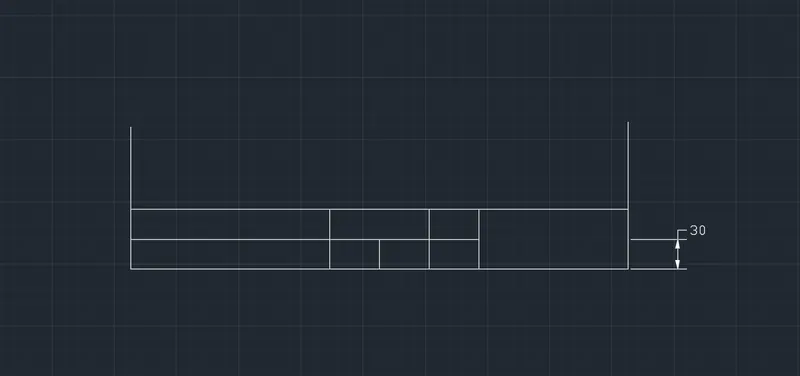
- Now take line and draw vertically from the center of the horizontal line.
- take offset of 50mm from forward and doward direction from the center line
STEP-3
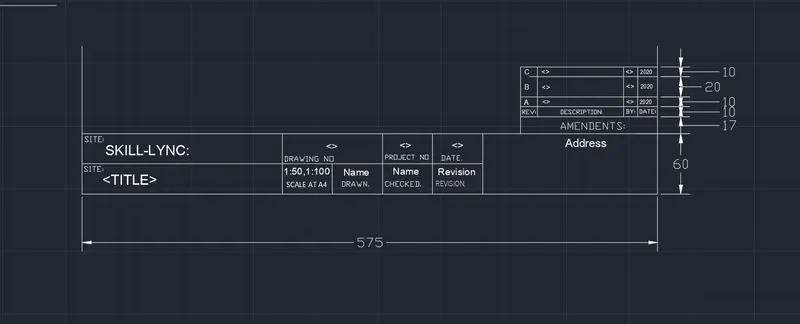
- Again take line command and draw the corner table with the help of line command
- take offset 17mm upward direction
- again take offset 10mm
- again take offseet 10mm
- again take offset 20mm
- again take offset 10mm
- Go to text command and write all the written content A,B,C, , amendents , address name time etc.
STEP-4
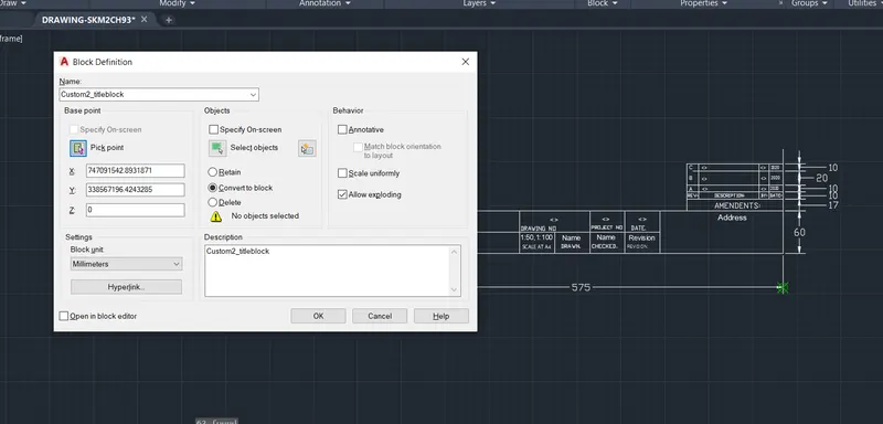
CREAT BLOCK
- Now go to the final part o the drawing
- select all the autocad drawing object than enter block command in the command bar.
- Now put the name Custom2_titleclock in the name box
- pik up point of this object
- than go to description part and describe about this
- now press okk
- this object is converted in to the block.
STEP-5
White layout drawing
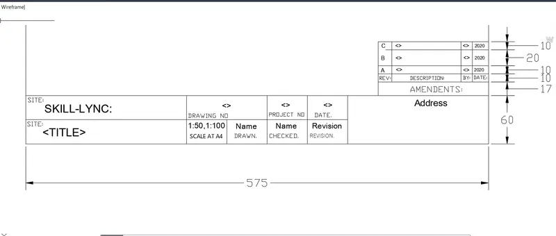
RESULT: Given templets custom1_titleblock and custom2_titleblock are completed according to given templets the autocad drawing link have attached with result. and screenshots are also attached.
AUTOCAD DRAWING LINK:
https://web.autocad.com/acad/me/sid/shares/drawings/177fd18b-3665-49c9-957a-b0bee098a586/editor
https://web.autocad.com/acad/me/sid/shares/drawings/177fd18b-3665-49c9-957a-b0bee098a586/editor
DRAWING NO. -1
DRAWING NO. -2
QUESTION NO. -2
ANSWER:
AIM: Create the doors type for warehouse as shown in the Figure. You need to create each door type as per standard size or given dimensions. Create the blocks of this door type after creating them.
INTRODUCTION: FOR START THIS DRAWING FIRST OF ALL WE HAVE TO DO SOME SETTINGS ACCORDING THE DRAWING -
DRAWING LINK
https://web.autocad.com/acad/me/sid/shares/drawings/7a9cbda0-674c-4ab5-9627-bd75a3240657/editor
SOFTWARE SETTINGS
SETTINGS - OPEN AUTOCAD
- SET DEFAULT SETTINGS - METRIC UNIT (mm)
- SELECT A TEMPLATE - ACCORDING TO DRAWINGS
- SELECT A WIZAED - ADVANCED SETUP
- UNITS - DECIMAL (mm)
- ANGLE - DECIMAL DEGREES
- ANGLE MEASURE - ACCORDING TO PLAN
- ANGLE DIRECTION - COUNTER CLOCKWISE
- AREA - ACCORDING TO PLAN
After this enter "D" for dimetion unit and set primary unit DECIMAL set precision 0
MODES -
- GRID ON BY F7 'CONTROL+G'
- USE ORTHO MODE FOR STRAIGHT 90 DEGREE ACCRDING NEED(F8)
- ON POLAR TRACKING (F10) SET ANGLE (15,30,45)
- OBJET SNAP TRACKING (F11)
- OBJECT SNAP (F3)
- TRANPARANCY ON WHEN YOU NEED
PROCEDURE:
DRAWING OF DOOR-1
STEP-1
- To draw door-1 take rectangle command
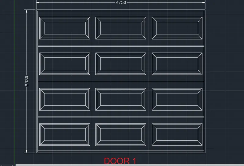
- and draw a rectangle 2750 x 2330 mm
- Now take offset of 20 mm from internal part
- again take offset of 30mm from verticle line
- Now this box divied into four equle part.
- for one part take offset of 572 mm
- again take 572 and 20m this done tree time.
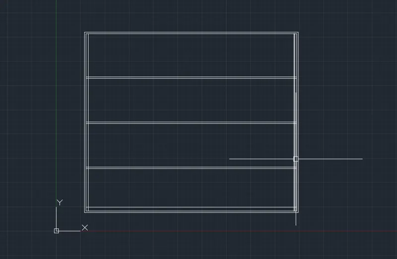
STEP-2
- Now start to divide vertically three part of the box
- For dividaton take offset of 883 mm from vertical line to +X direction.
- So now We can see the door divided into 9 equal boxes.
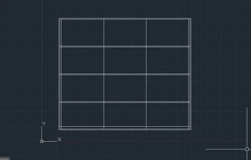
STEP-3
- For drawing the design of the gate we start to draw a corner box.
- take 20mm ofset from vertical line and 100mm from upper horizontal line
- Again take 20mm offset and 75mm upper bottom line.
- with the help of trim command trim all the unwanted lines.
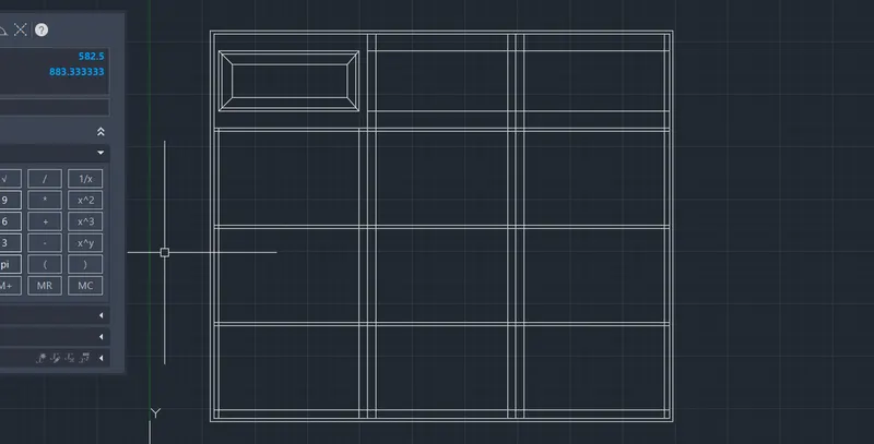
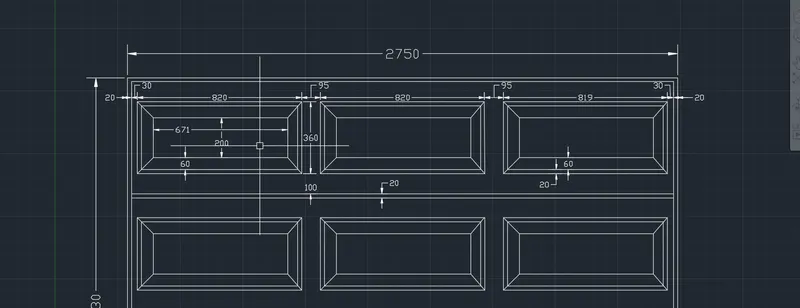
STEP-4
- This drawing is attached for dimention refrence of design.
STEP-5
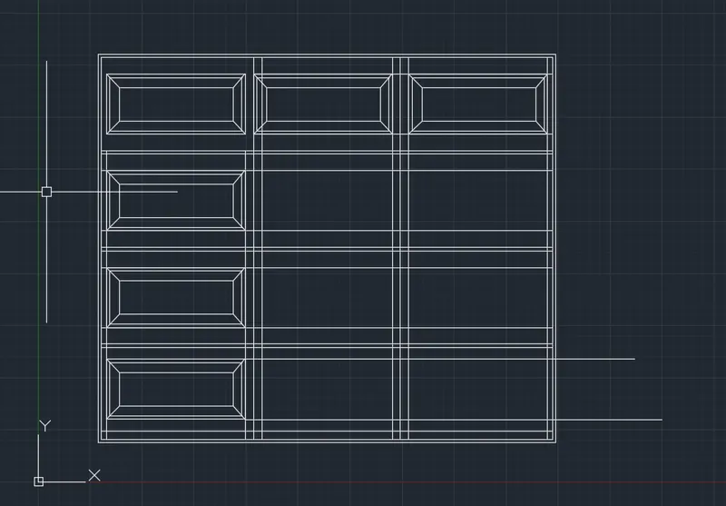
- Copy the corner design and put it horizontally in the three boxes.
- again with the help of copy command put it vertically
- For putting the design we use projection line.
STEP-6
- With the help of trim or delete command trim all the unwanted line or delete .
- Now The door-1 is Complete.
CREAT BLOCK
- Now go to the final part of the drawing
- Select single autocad drawing object than enter block command in the command bar.
- Now put the name of the block DOOR-1 in the name box
- pik up point of this object
- than go to description part and describe about this
- now press okk
- this object is converted in to the block.
- all types of block of the symbol is drawn and attached with this project.
DRAWING OF DOOR-2
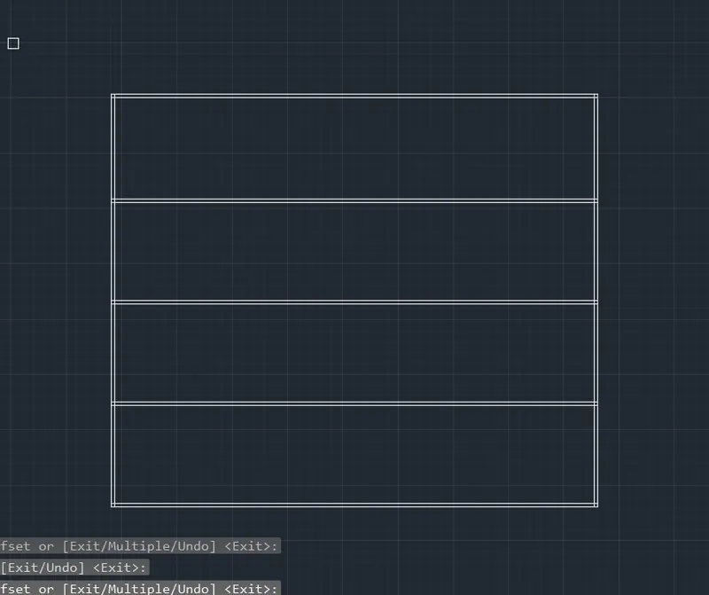
STEP-1
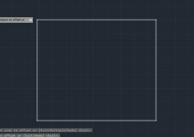
- To draw door-1 take rectangle command
- and draw a rectangle 2750 x 2330 mm
- Now take offset of 20 mm from internal part
STEP-2
- again take offset of 30mm from verticle line
- Now this box divied into four equle part.
- for one part take offset of 572 mm
- again take 572 and 20m this done tree time.
STEP-3
- Now start making handle of the door
- to draw the handle tal rectangle with 20 x 100mm
- again take rectangle 100 x 20 and put it abbove the previous rectangle.
- fillet both corner of the rectangle.
CREAT BLOCK
- Now go to the final part of the drawing
- Select single autocad drawing object than enter block command in the command bar.
- Now put the name of the block DOOR-2 in the name box
- pik up point of this object
- than go to description part and describe about this
- now press okk
- this object is converted in to the block.
- all types of block of the symbol is drawn and attached with this project.
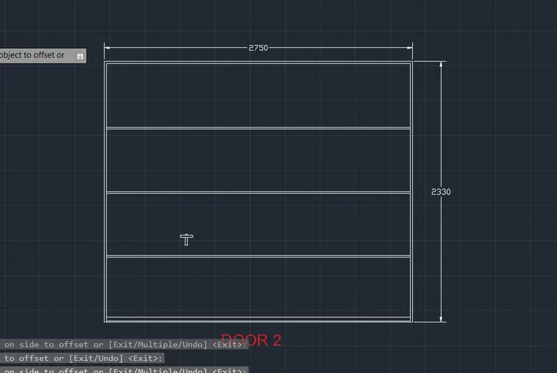
RESULT: Given Door-1 and Door-2 are completed according to given drawings. the autocad drawing link have attached with result. and screenshots are also attached.
AUTOCAD DRAWING LINK:
https://web.autocad.com/acad/me/sid/shares/drawings/7a9cbda0-674c-4ab5-9627-bd75a3240657/editor
https://web.autocad.com/acad/me/sid/shares/drawings/7a9cbda0-674c-4ab5-9627-bd75a3240657/editor
DRAWING NO. -1
DRAWING NO. -2
QUESTION NO. -3
ANSWER:
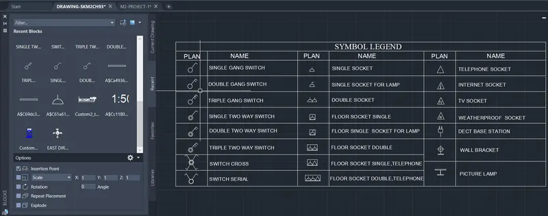
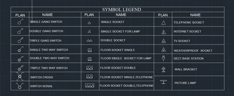
AIM: Create each symbol as a block with the name given in the legend. After creating the blocks arrange them in the legend as shown in the Figure
INTRODUCTION: FOR START THIS DRAWING FIRST OF ALL WE HAVE TO DO SOME SETTINGS ACCORDING THE DRAWING -
SOFTWARE SETTINGS
SETTINGS - OPEN AUTOCAD
- SET DEFAULT SETTINGS - METRIC UNIT [mm]
- SELECT A TEMPLATE - ACCORDING TO DRAWINGS
- SELECT A WIZAED - ADVANCED SETUP
- UNITS - DECIMAL [mm]
- ANGLE - DECIMAL DEGREES
- ANGLE MEASURE - ACCORDING TO PLAN
- ANGLE DIRECTION - COUNTER CLOCKWISE
- AREA - ACCORDING TO PLAN
After this enter "D" for dimetion unit and set primary unit DECIMAL set precision 0
MODES -
- GRID ON BY F7 'CONTROL+G'
- USE ORTHO MODE FOR STRAIGHT 90 DEGREE ACCRDING NEED(F8)
- ON POLAR TRACKING (F10) SET ANGLE (15,30,45)
- OBJET SNAP TRACKING (F11)
- OBJECT SNAP (F3)
- TRANPARANCY ON WHEN YOU NEED
PROCEDURE:
STEP-1
TO DRAW THIS TEMPLAT FIRST OF ALL WE HAVE TO DRAW THE PARTICULAR SYMBOL AND ALSO MAKE PARICULAR BLOCK OF THE SYMBOL SO NOW WE START DRAW THE SYMBOL WITH THE HELP OF AUTOCAD.
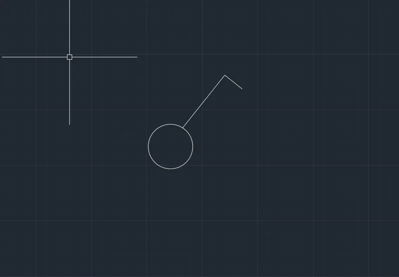
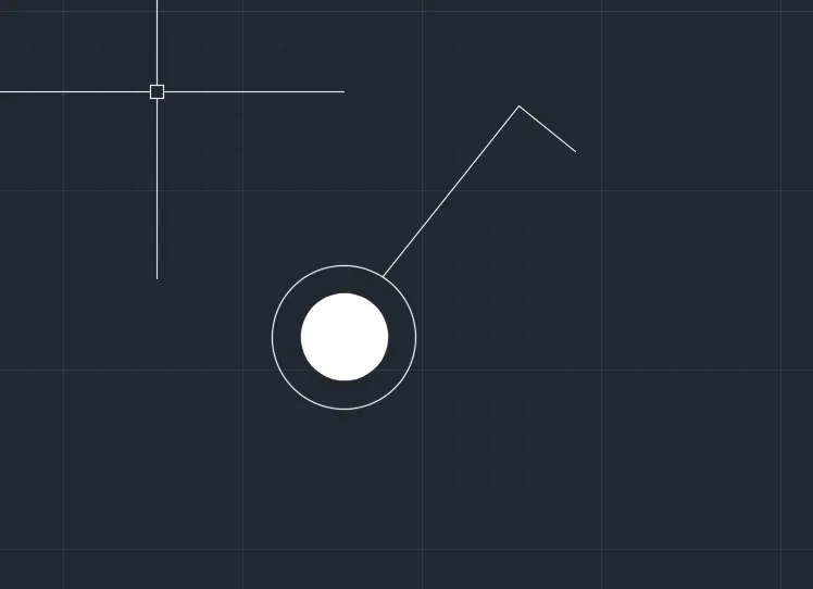
SINGLE GANG SWITCH:
- Take circle command and draw circle with radius of dia of 10mm
- take line and puut it an angle below right agnle with 15mm distance
- now draw 5 mm 90 from last line enf point
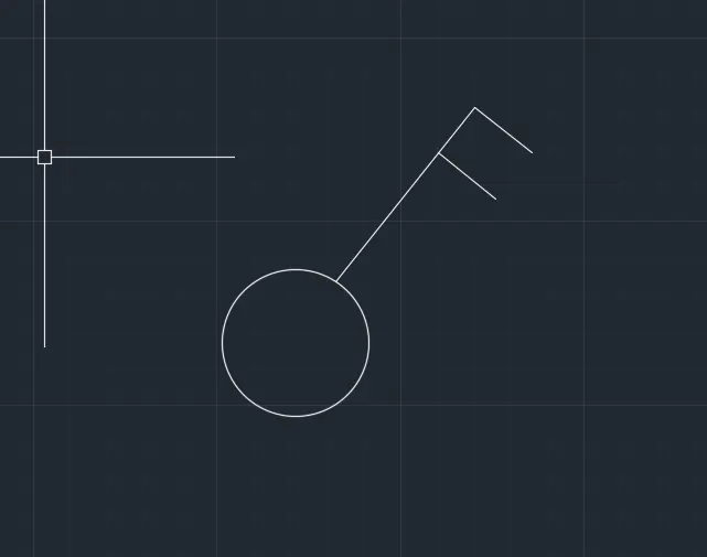
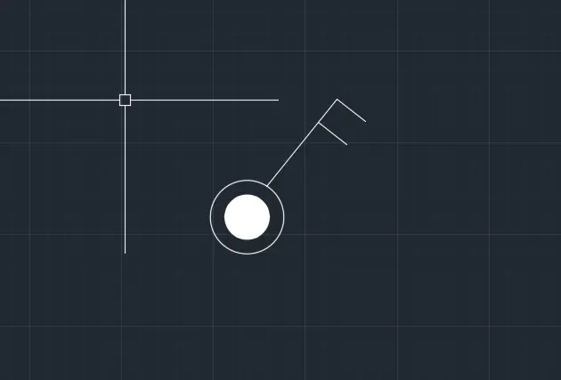
DOUBLE GANG SWITCH:
- Take circle command and draw circle with radius of dia of 10mm
- take line and puut it an angle below right agnle with 15mm distance
- now draw 5 mm 90 from last line enf point
- again take offset 4mm
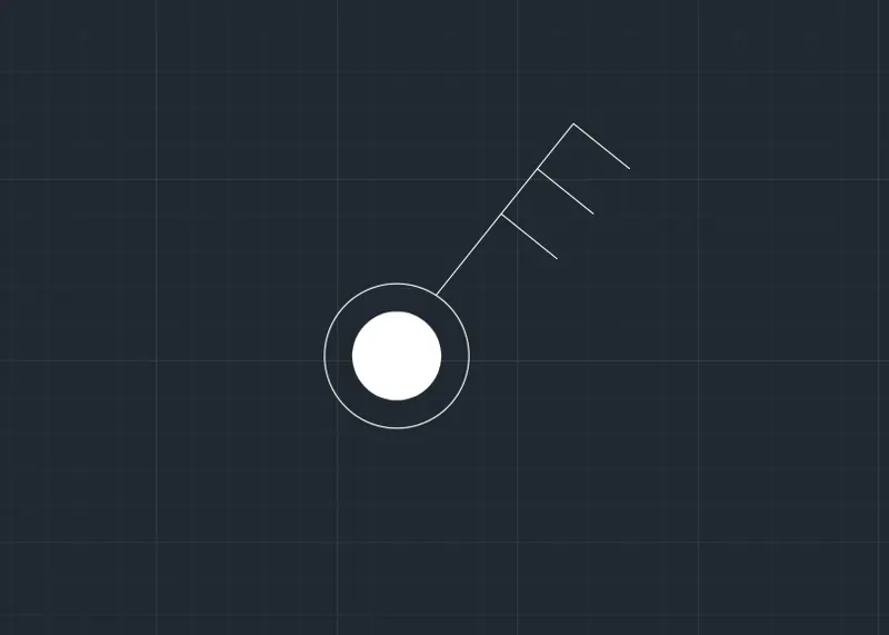
TRIPLE GANG SWITCH:
- Take circle command and draw circle with radius of dia of 10mm
- take line and puut it an angle below right agnle with 15mm distance
- now draw 5 mm 90 from last line enf point
- again take offset 4mm
- again take offset 4mm

STEP-2
SNGLE TWO WAY SWITCH
- Take circle command and draw circle with radius of dia of 10mm
- draw internal circle of dia 6mm
- take line and puut it an angle below right agnle with 15mm distance
- now draw 5 mm 90 from last line end point
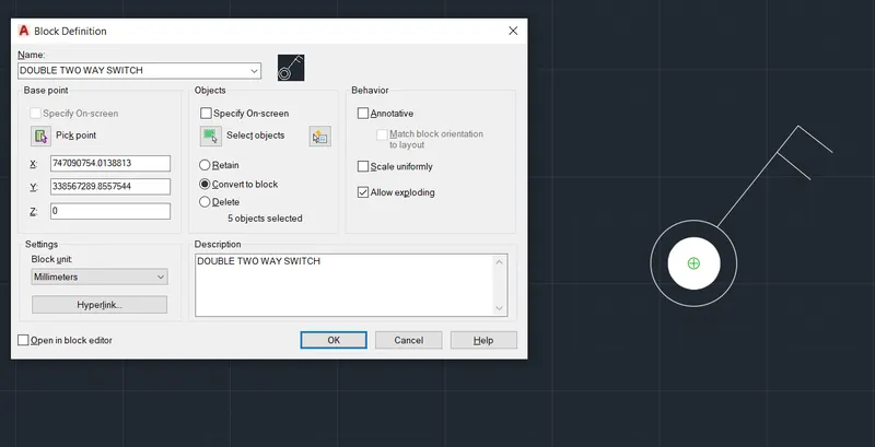
DOUBLE TWO WAY SWITCH
- Take circle command and draw circle with radius of dia of 10mm
- draw internal circle of dia 6mm .
- take line and puut it an angle below right agnle with 15mm distance
- now draw 5 mm 90 from last line enf point
- again take offset 4mm
TRIPLE TWO WAT SWITCH
- Take circle command and draw circle with radius of dia of 10mm
- draw internal circle of dia 6mm
- take line and puut it an angle below right agnle with 15mm distance
- now draw 5 mm 90 from last line enf point
- again take offset 4mm
- again take offset 4mm
STEP-3
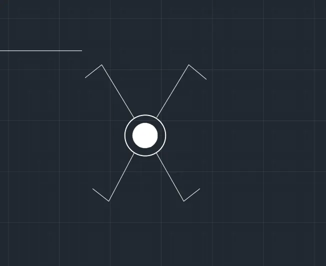
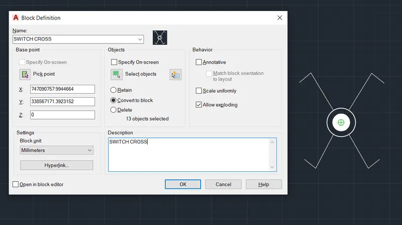
SWITCH CROSS
- Take circle command and draw circle with radius of dia of 10mm
- draw internal circle of dia 6mm
- take line and puut it an angle below right agnle with 15mm distance
- now draw 5 mm 90 from last line enf point
- take mirror command to both side of the drawing. upwaard and downward.
SWITCH SERIAL
- Take circle command and draw circle with radius of dia of 10mm
- draw internal circle of dia 6mm
- take line and puut it an angle below right agnle with 15mm distance
- now draw 5 mm 90 from last line enf point
- take mirror command to singl side of the drawing outside.

STEP-4
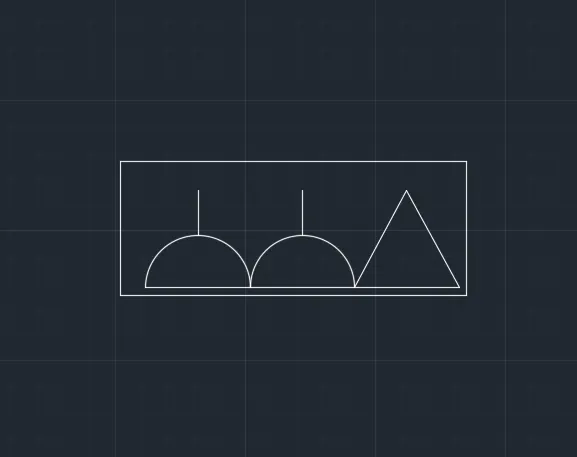
SINGLE SOCKET
- Take line of 10mm
- draw a arc with help of endpoint of the line
- Take line command and take verticle from the arch center point to upward 5mm.
SINGLE SOCKET FOR LAMP
- Take line of 10mm
- draw a arc with help of endpoint of the line
- Take line command and take verticle from the arch center point to upward 5mm.
- take line 5mm from vertical endpoint with 90 degree +x direction.
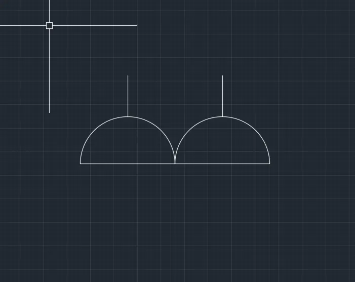
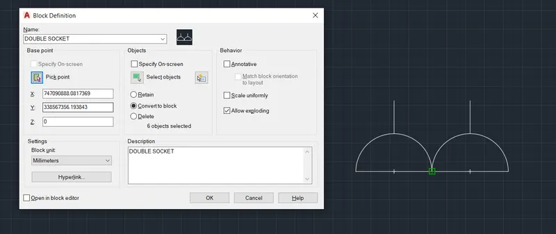
DOUBLE SOCKET
- copy the single socket and past it
- take mirror command to draw two single socket which are connected.
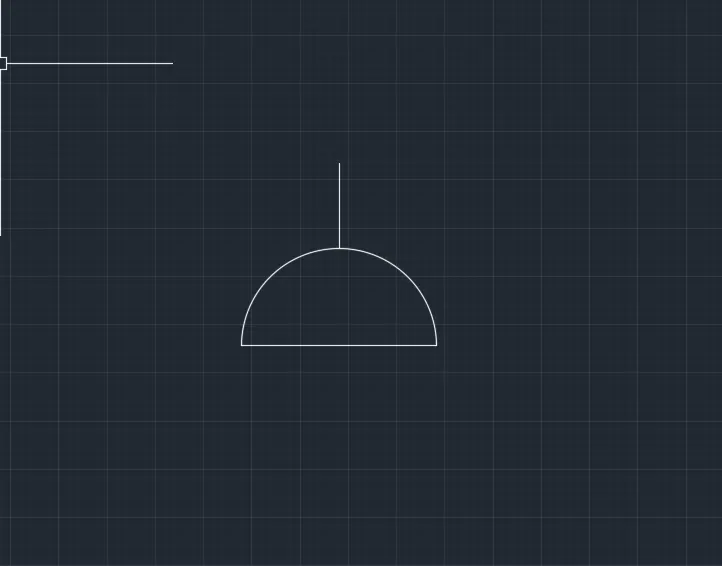
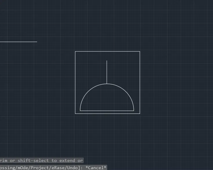
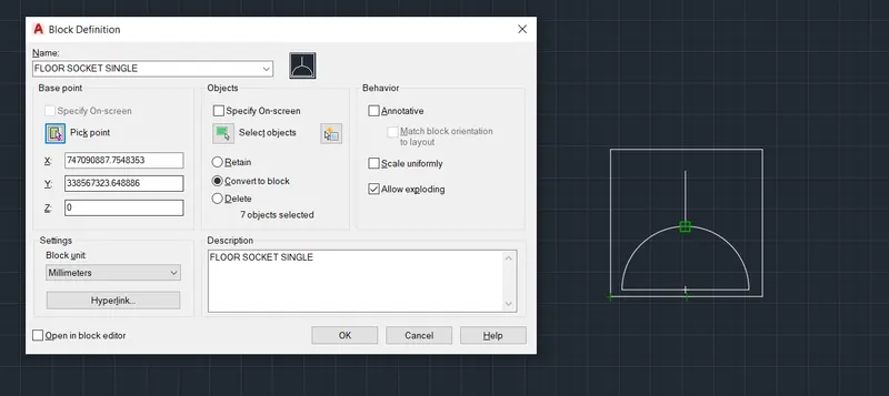
FLOOR SOCKET
- Take line of 10mm
- draw a arc with help of endpoint of the line
- Take line command and take verticle from the arch center point to upward 5mm.
- put it under the rectangle.
STEP-5
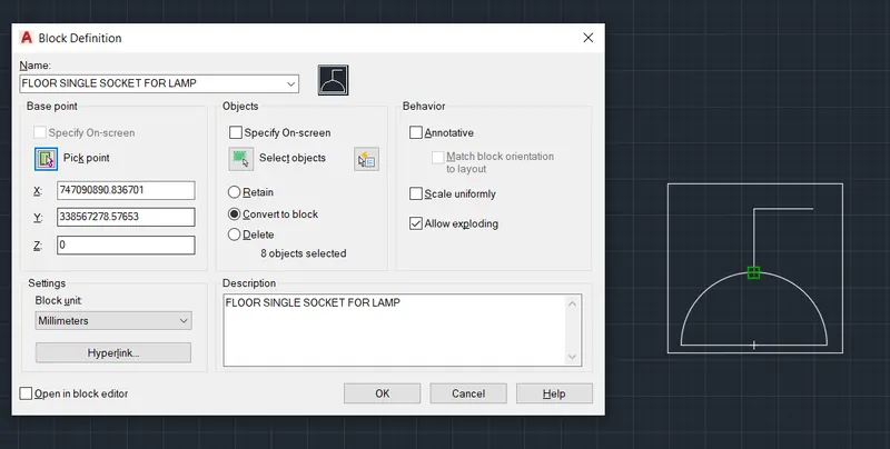
FLOOR SINGLE SOCKET FOR LAMP
- Take line of 10mm
- draw a arc with help of endpoint of the line
- Take line command and take verticle from the arch center point to upward 5mm.
- put it under the rectangle.
- take line 5mm from vertical endpoint with 90 degree +x direction.
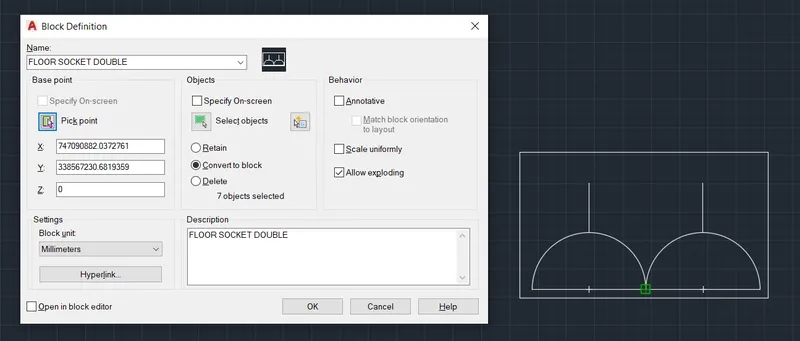
FLOOR SOCKET DOUBLE
- Take line of 10mm
- draw a arc with help of endpoint of the line
- copy the single socket and past it
- take mirror command to draw two single socket which are connected.
- put it under the rectangle.
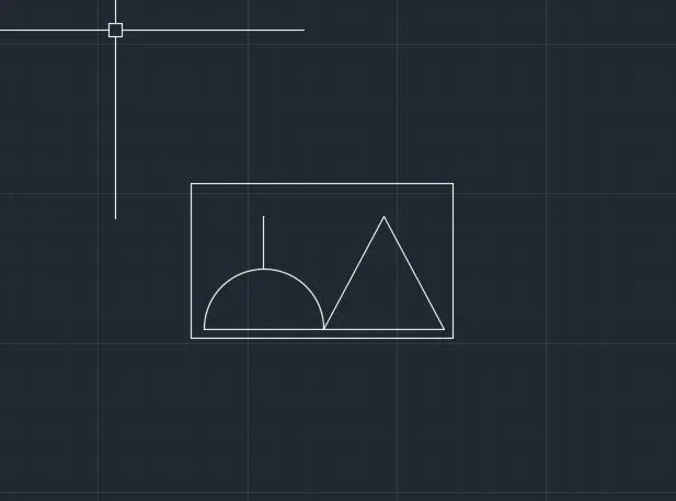
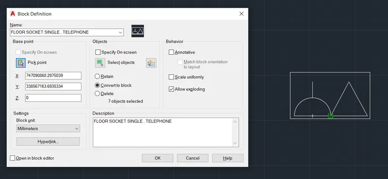
FLOOR SOCKET SINGLE, TELEPHONE
- drawv single socket with triangle.
FLOOR SOCKET DOUBLE , TELEPHONE
- draw double socket with triangle.
STEP-6
CREAT BLOCK
- Now go to the final part of the drawing
- select single autocad drawing object than enter block command in the command bar.
- Now put the name of the block in the name box
- pik up point of this object
- than go to description part and describe about this
- now press okk
- this object is converted in to the block.
- all types of block of the symbol is drawn and attached with this project.
CREAT BLOCK
CREAT BLOCK
CREAT BLOCK
CREAT BLOCK
CREAT BLOCK
CREAT BLOCK
CREAT BLOCK
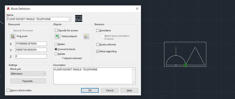
CREAT BLOCK
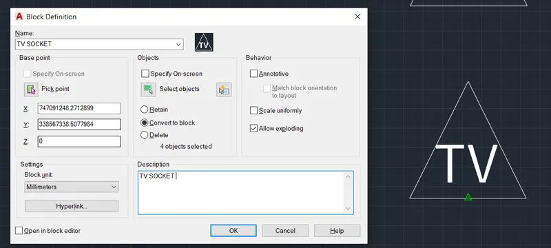
CREAT BLOCK
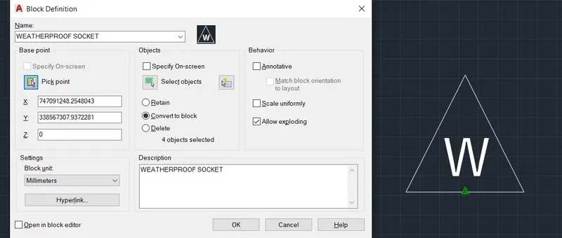
CREAT BLOCK
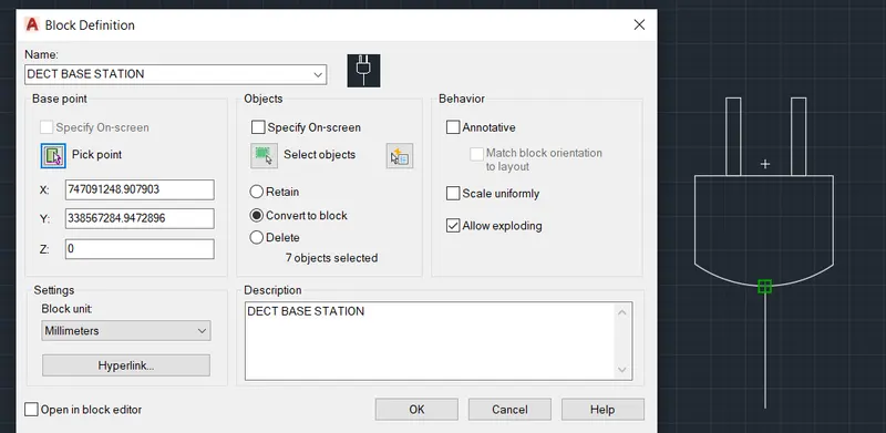
CREAT BLOCK
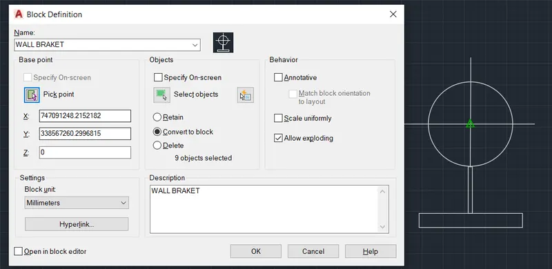
CREAT BLOCK
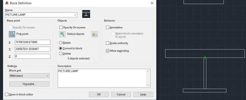
STEP-7
TABLE:
AFTER CREATING THE PARTICULAR BLOCK OF THE OBJECT WE HAVEE TO INSERT IT IN THE TABLE , BUT BEFORE INSERTING WE HAVE TO DRAW THE TABLE ,SO NOW WE START THE DRAWING THE TABLE.
- Take line comand to creat the table take a horizontal line and take a vertical line
- take offset of 70mm from vertical line
- again take 200 mm offset
- agin take 70 mm offset
- again tke 200 mm offset now again take 70 mm
- and again take 200 mm offset .
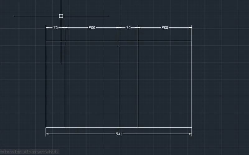
STEP-8
- Start taking offset 20 mm two times from upward direction to downward direction.
- now take offset 30mm
- we know that the numbers of the row is 8 so we have to take offset 8 times.
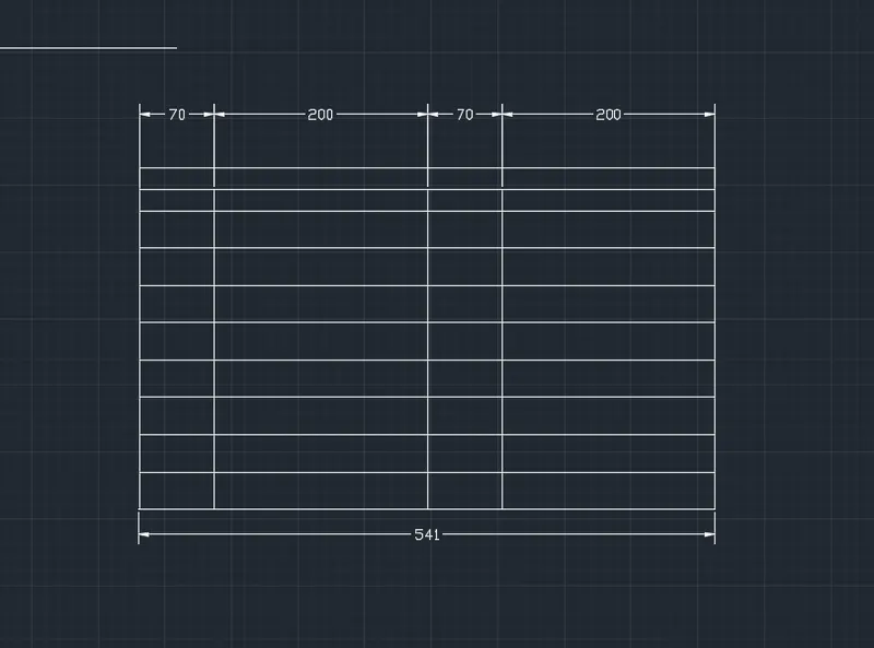
STEP-9
- Go to the mtext command and write the written data like symbol legend , Plan and Name of the legend.
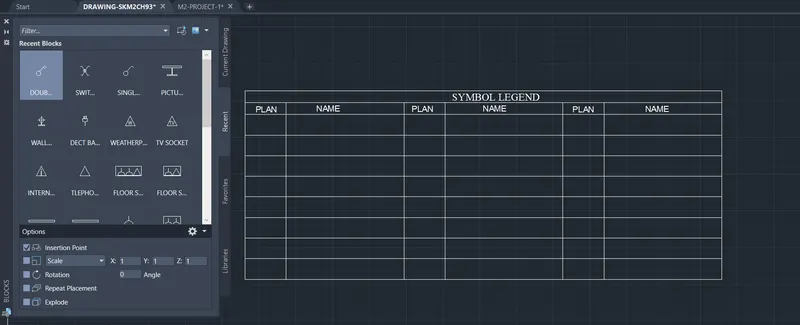
STEP-9
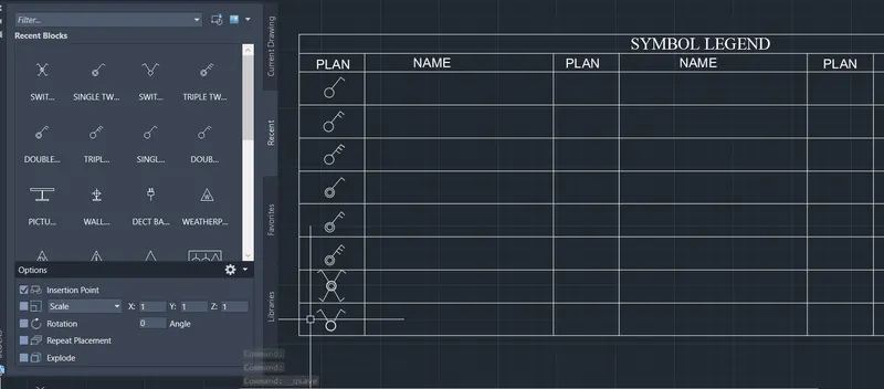
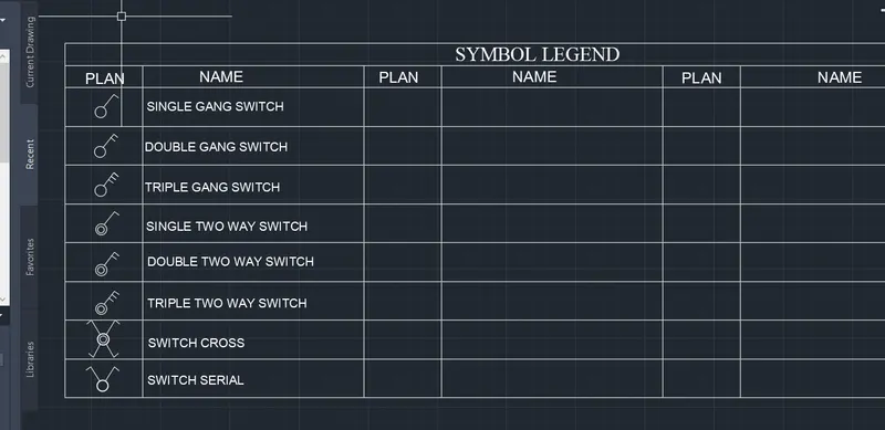
INSERT BLOCK:
- After completing the table we will start to inserting the object in the table and
- start inserting single gang socket
- After inserting with the help of Mtext comand write the name of the block
INSERT BLOCK:
INSERT BLOCK:
INSERT BLOCK:
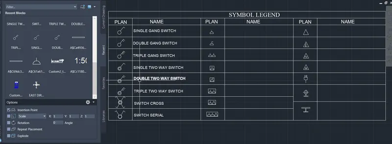
- All blockes are inserted now we start wrting name of the block
- After inserting with the help of Mtext comand write the name of the block
RESULT:
: Given SYMBOL as a block with name given in the legend are completed according to given templets after maling drawing i had to converted into block than inserted into the table . the autocad drawing link have attached with result. and screenshots are also attached.
AUTOCAD DRAWING LINK:
https://web.autocad.com/acad/me/sid/shares/drawings/348737bc-f887-4bc0-b265-ab6fac1fc36a/editor
https://web.autocad.com/acad/me/sid/shares/drawings/348737bc-f887-4bc0-b265-ab6fac1fc36a/editor
RESULTANRT DRAWING
QUESTION NO. -4
ANSWER:
AIM: Create the door type for residential building as a block. Save the name of the blocks as type. Use given dimensions or assume dimensions as per industry standards.
INTRODUCTION:FOR START THIS DRAWING FIRST OF ALL WE HAVE TO DO SOME SETTINGS ACCORDING THE DRAWING -
DRAWING LINK
https://web.autocad.com/acad/me/sid/shares/drawings/177fd18b-3665-49c9-957a-b0bee098a586/editor
https://web.autocad.com/acad/me/sid/shares/drawings/177fd18b-3665-49c9-957a-b0bee098a586/editor
SOFTWARE SETTINGS
SETTINGS - OPEN AUTOCAD
- SET DEFAULT SETTINGS - IMPERIAL UNITS [FEAT AND INCHES]
- SELECT A TEMPLATE - ACCORDING TO DRAWINGS
- SELECT A WIZAED - ADVANCED SETUP
- UNITS - ENGINEERING
- ANGLE - DECIMAL DEGREES
- ANGLE MEASURE - ACCORDING TO PLAN
- ANGLE DIRECTION - COUNTER CLOCKWISE
- AREA - ACCORDING TO PLAN
After this enter "D" for dimetion unit and set primary unit DECIMAL set precision 0
MODES -
- GRID ON BY F7 'CONTROL+G'
- USE ORTHO MODE FOR STRAIGHT 90 DEGREE ACCRDING NEED(F8)
- ON POLAR TRACKING (F10) SET ANGLE (15,30,45)
- OBJET SNAP TRACKING (F11)
- OBJECT SNAP (F3)
- TRANPARANCY ON WHEN YOU NEED
PROCEDURE:
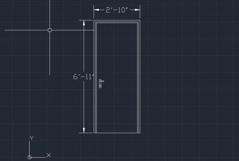
FOR D1-DOOR
STEP-1
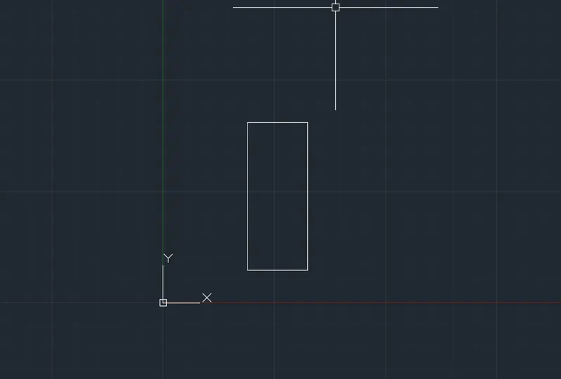
- To draw this go to rectangle command and specify first point draw a rectangle with the dimension of 2'-10" x 6'-11"
STEP-2
- Now take offset of 1.20" of the rectangle IN the internal side
- Again take offset of 0.79 of the rectangle
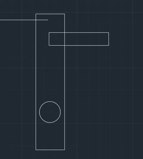
HANDLE DRAWING
- start to draw the handle of the door
- for the handle take rrec withthe size of 2"x6"
- again take rectangle and draw rec with 3"x1"
- Now put it above the rectangle upper corner point.
FOR D2-DOOR
STEP-1
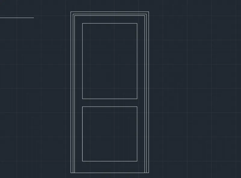
- To draw this go to rectangle command and specify first point draw a rectangle with the dimension of 3'-4" x 6'-11"
STEP-2
- Now take offset of 1.20" of the rectangle IN the internal side
- Again take offset of 0.79 of the rectangle
- now Again take offset of 100 mm of the rectangle both side of the door in the internal side
- in the bottom side draw the squre with reminning width.
STEP-3
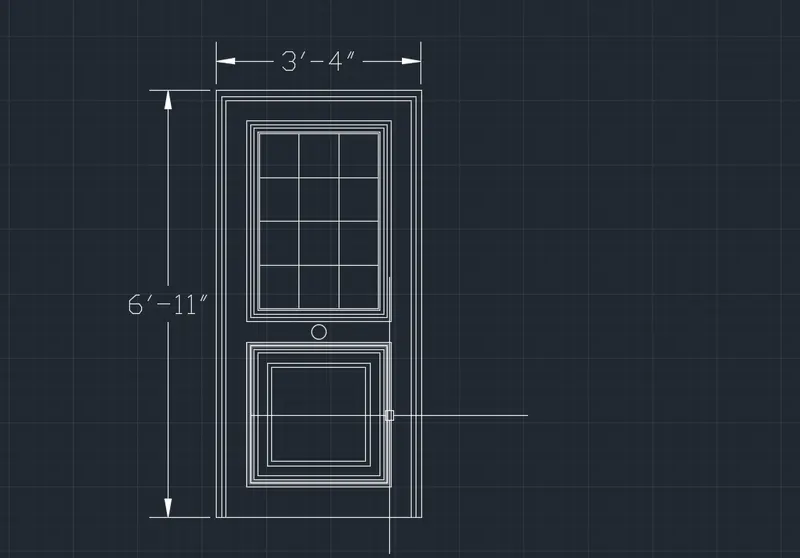
- Now we start design part , for this take offset of .79"mm
- again take offset 0.79 "
- again take offset 0.79"
- Now Change the offset and put o.40" offset of the last offset.
- remainning area divide 4 vertical part and 3 horizontal part.
STEP-4
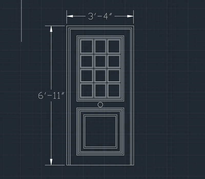
- Start to Draw corner design with the help of line and trim command
- take offset of 0.40"
- and trim all the unwanted lines. with the help of trim command.
- Now use copy command to copy the corner design and put it in the 9 equal column.
- for putting this we can use construction vertical or horizontal line.
- Start to draw the bottom rectangle of the drawing.
- for this take offset of .79" internal side
- Again take offset 0.79 "of the rectangle
- Again take offset 0.79"of the rectangle
- Now take offset 2" of the rectangle
- Again take offset 0.79"of the rectangle
- So in the last draw the circle with the help of circle command with dia of 3"
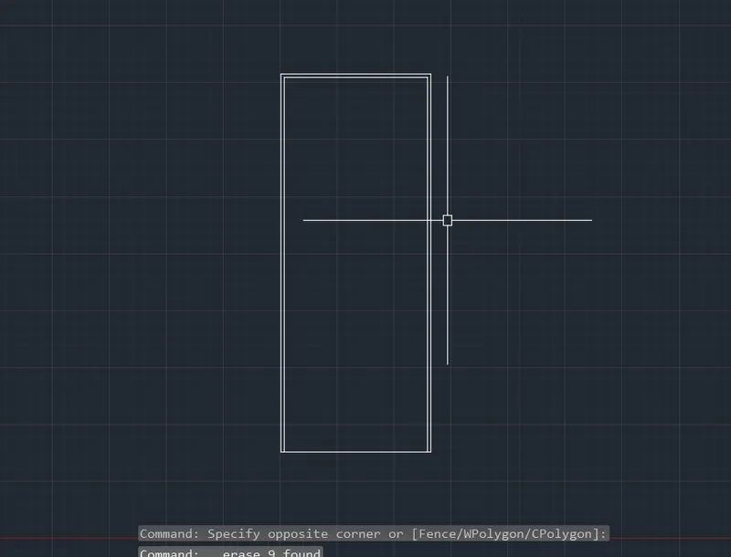
FOR D3-DOOR
STEP-1
- To draw this go to rectangle command and specify first point draw a rectangle with the dimension of 2'-10" x 6'-11"
- And take offset of 0.79" from the rectange.
STEP-2
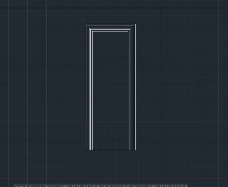
- Now take offset of 2" of the rectangle IN the internal side
- Again take offset of 0.79 of the rectangle
- And again take offset 1.2"
STEP-3
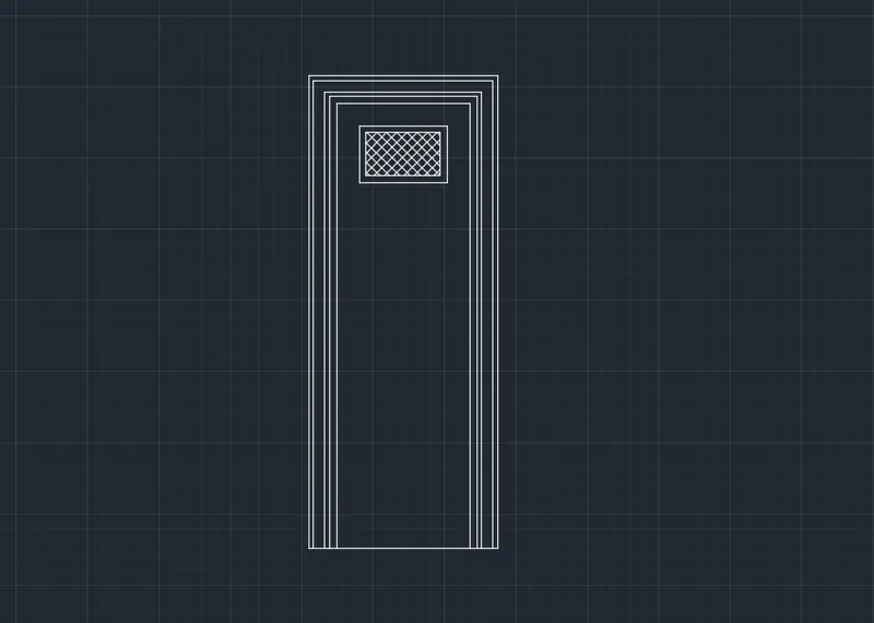
- Now we have to draw the jali window of the drawing.
- for this take offset of 4" in the internal side from all 3 side
- for this take offset of 1.2" in the internal side from all 3 side
STEP-4
HACHING:
- Go to hatching command and put the grid hatching in the jali window.
FOR D4-DOOR
STEP-1
- To draw this go to rectangle command and specify first point draw a rectangle with the dimension of 2'-10" x 6'-11"
STEP-2
- Now take offset of 1.20" of the rectangle IN the internal side
- Again take offset of 0.79 of the rectangle
- now Again take offset of 100 mm of the rectangle both side of the door in the internal side
- in the bottom side draw the squre with reminning width.
STEP-3
- Now we start design part , for this take offset of .79"mm
- Again take offset 0.79 "
- Again take offset 0.79"
- Now Change the offset and put o.40" offset of the last offset.
- Remainning area divide 4 vertical part and 3 horizontal part.
- Start to Draw corner design with the help of line and trim command
- take offset of 0.40"
- And trim all the unwanted lines. with the help of trim command.
- Now use copy command to copy the corner design and put it in the 12 equal column.
- For putting this we can use construction vertical or horizontal line.
- Start to draw the bottom rectangle of the drawing.
- For this take offset of .79" internal side
- Again take offset 0.79 "of the rectangle
- Again take offset 0.79"of the rectangle
- Now take offset 2" of the rectangle
- Again take offset 0.79"of the rectangle
- So in the last draw the circle with the help of circle command with dia of 3"
STEP-4
- Arch drawing of the drawing.
- Take circle of with (tan,tan,tan ) command .
- now trim half bottom side circle with the help of trim command.
- take offset 1.2" internal side of the arch
- Again take offset 0.79"
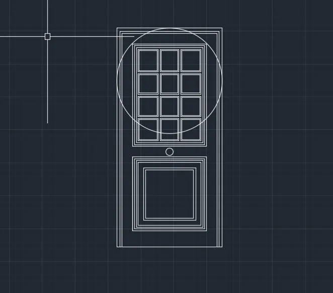
- Again take offset 4"
- with the help of trim command trim all the unwanted lines.
- Drawing the internal corner design shown in the figure.
- Now we start bottom rectangle design part , for this take offset of .79"mm
- Again take offset 0.79 "
- Again take offset 0.79"
- Now Change the offset and put o.40" offset of the last offset.
- Remainning area divide 3 vertical part and 3 horizontal part.
- Start to Draw corner design with the help of line and trim command
- take offset of 0.40"
- And trim all the unwanted lines. with the help of trim command.
- Now use copy command to copy the corner design and put it in the 9 equal column.
- For putting this we can use construction vertical or horizontal line.
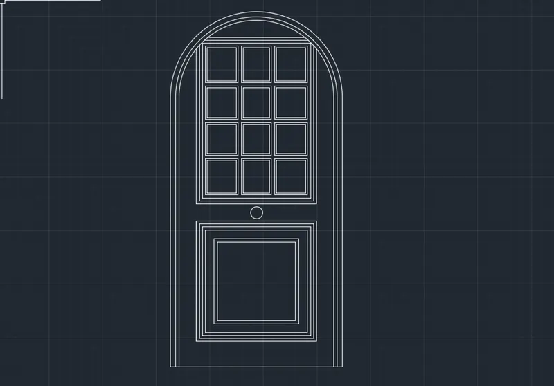
- With the help of trim or delete command delete all the unwanted lines.
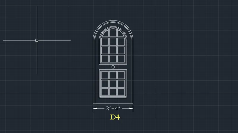
FOR D5-DOOR
STEP-1
- To draw this go to rectangle command and specify first point draw a rectangle with the dimension of 2'-10" x 6'-11"
- Now take offset of 1.20" of the rectangle IN the internal side
- Again take offset of 0.79 of the rectangle
STEP-2
- Now Again take offset of 100 mm of the rectangle both side of the door in the internal side
- In the bottom side draw the squre with reminning width.
- Now we start design part , for this take offset of .79"mm
- Again take offset 0.79 "
- Again take offset 0.79"
STEP-3
- Now Change the offset and put o.40" offset of the last offset.
- Remainning area divide 4 vertical part and 3 horizontal part.
- Start to Draw corner design with the help of line and trim command
- Take offset of 0.40"
- And trim all the unwanted lines. with the help of trim command.
STEP-4
- Now use copy command to copy the corner design and put it in the 9 equal column.
- For putting this we can use construction vertical or horizontal line.
- Start to draw the bottom rectangle of the drawing.
- For this take offset of .79" internal side
- Again take offset 0.79 "of the rectangle
- Again take offset 0.79"of the rectangle
STEP-5
- Now take offset 2" of the rectangle
- Again take offset 0.79"of the rectangle
- So in the last draw the circle with the help of circle command with dia of 3"
- With the help of trim or delete command delete all the unwanted lines.
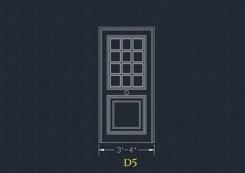
FOR D6-DOOR
STEP-1
- To draw this go to rectangle command and specify first point draw a rectangle with the dimension of 2'-10" x 6'-11"
- Now take offset of 1.20" of the rectangle IN the internal side
- Again take offset of 0.79 of the rectangle
STEP-2
- Now Again take offset of 100 mm of the rectangle both side of the door in the internal side
- In the bottom side draw the squre with reminning width.
- Now we start design part , for this take offset of .79"mm
- Again take offset 0.79 "
- Again take offset 0.79"
STEP-3
- Now Change the offset and put o.40" offset of the last offset.
- Remainning area divide 4 vertical part and 3 horizontal part.
- Start to Draw corner design with the help of line and trim command
- Take offset of 0.40"
- And trim all the unwanted lines. with the help of trim command.
STEP-4
- Now use copy command to copy the corner design and put it in the 9 equal column.
- For putting this we can use construction vertical or horizontal line.
- Start to draw the bottom rectangle of the drawing.
- For this take offset of .79" internal side
- Again take offset 0.79 "of the rectangle
- Again take offset 0.79"of the rectangle
STEP-5
- Now take offset 2" of the rectangle
- Again take offset 0.79"of the rectangle
- So in the last draw the circle with the help of circle command with dia of 3"
- Again take offset 4"
- with the help of trim command trim all the unwanted lines.
- Drawing the internal corner design shown in the figure.
STEP-6
- Now we start bottom rectangle design part , for this take offset of .79"mm
- Again take offset 0.79 "
- Again take offset 0.79"
STEP-7
- Now Change the offset and put o.40" offset of the last offset.
- Remainning area divide 3 vertical part and 3 horizontal part.
- Start to Draw corner design with the help of line and trim command
- take offset of 0.40"
STEP-8
- And trim all the unwanted lines. with the help of trim command.
- Now use copy command to copy the corner design and put it in the 9 equal column.
- For putting this we can use construction vertical or horizontal line
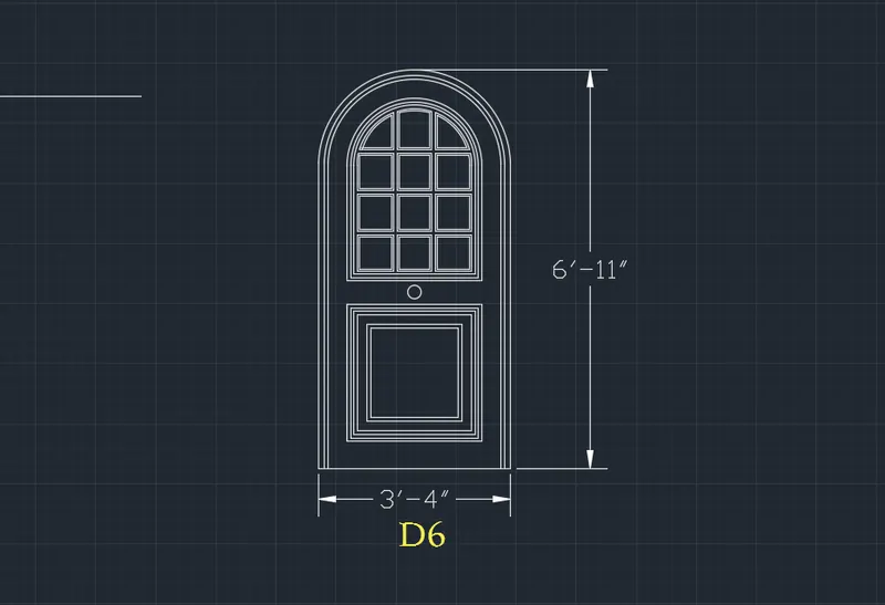
STEP-1
CREAT BLOCK
- Now go to the final part of the drawing
- select single autocad drawing object than enter block command in the command bar.
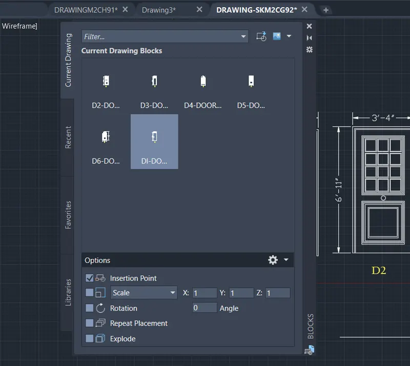
- Now put the name of the block D1, D2, D3, D4, D5, D6 in the name box
- pik up point of this object
- than go to description part and describe about this
- now press okk
- this object is converted in to the block.
- all types of block of the OBJECT is drawn and attached with this project.
RESULT:
: Given DOORS as a block with name given D1,D2,D3,D4,D5 are completed according to given templets after maKing drawing i had to converted into block . the autocad drawing link have attached with result. and screenshots are also attached.
AUTOCAD DRAWING LINK:
https://web.autocad.com/acad/me/sid/shares/drawings/348737bc-f887-4bc0-b265-ab6fac1fc36a/editor
https://web.autocad.com/acad/me/sid/shares/drawings/348737bc-f887-4bc0-b265-ab6fac1fc36a/editor
RESULTANRT DRAWING
D1
D2
D3
D4
D5
D6
QUESTION NO. -5
ANSWER:
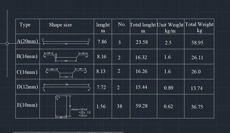
AIM: Create each shape as a block as shown in the Figure. Save the block and insert them on the table as shown in the Figure.
INTRODUCTION: FOR START THIS DRAWING FIRST OF ALL WE HAVE TO DO SOME SETTINGS ACCORDING THE DRAWING -
DRAWING LINK
https://web.autocad.com/acad/me/sid/shares/drawings/177fd18b-3665-49c9-957a-b0bee098a586/editor
https://web.autocad.com/acad/me/sid/shares/drawings/177fd18b-3665-49c9-957a-b0bee098a586/editor
SOFTWARE SETTINGS
SETTINGS - OPEN AUTOCAD
- SET DEFAULT SETTINGS - METRIC UNIT
- SELECT A TEMPLATE - ACCORDING TO DRAWINGS
- SELECT A WIZAED - ADVANCED SETUP
- UNITS - DECIMAL
- ANGLE - DECIMAL DEGREES
- ANGLE MEASURE - ACCORDING TO PLAN
- ANGLE DIRECTION - COUNTER CLOCKWISE
- AREA - ACCORDING TO PLAN
After this enter "D" for dimetion unit and set primary unit DECIMAL set precision 0
MODES -
- GRID ON BY F7 'CONTROL+G'
- USE ORTHO MODE FOR STRAIGHT 90 DEGREE ACCRDING NEED(F8)
- ON POLAR TRACKING (F10) SET ANGLE (15,30,45)
- OBJET SNAP TRACKING (F11)
- OBJECT SNAP (F3)
- TRANPARANCY ON WHEN YOU NEED
PROCEDURE:
TO DRAW THIS TEMPLAT FIRST OF ALL WE HAVE TO DRAW THE PARTICULAR SYMBOL AND ALSO MAKE PARICULAR BLOCK OF THE SYMBOL SO NOW WE START DRAW THE SYMBOL WITH THE HELP OF AUTOCAD.
STEP-1
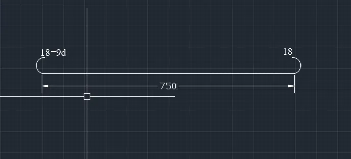
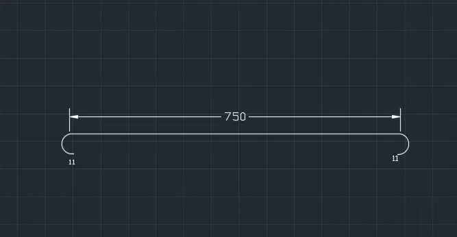
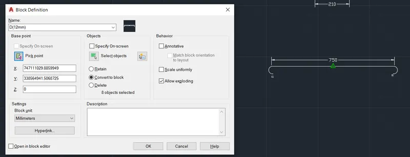
A(20MM)
- To draw the diagram take line command draw line of 750 mm
- draw circle upper side and trim it vertically half
- than ise mirror command to draw it second side
STEP-2
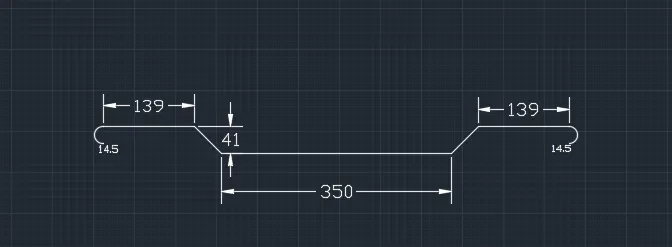
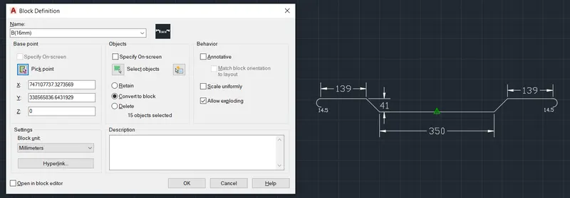
B(16MM)
- To draw this shap take line of 350 distance.
- now take line with end point and draw 45degree angle
- start draw line 139 mm from last point
- now select and mirror it.
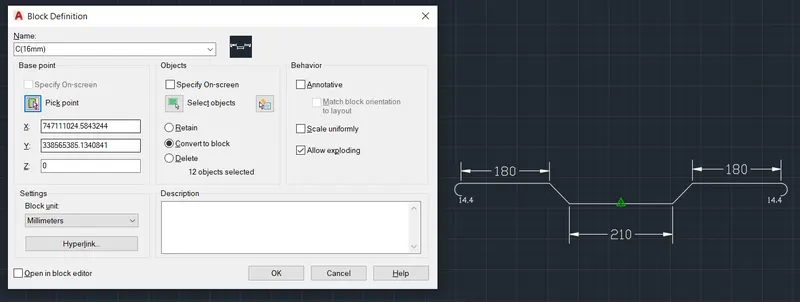
STEP-3
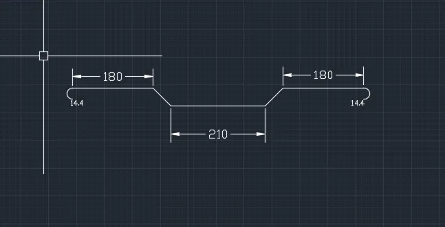
C(16mm)
- To draw this shap take line of 210 distance.
- now take line with end point and draw 45degree angle
- start draw line189 mm from last point
- now select and mirror it To the center point
STEP-4
- To draw the diagram take line command draw line of 750 mm
- draw circle bottom side and trim it vertically half
- than ise mirror command to draw it second side
STEP-5
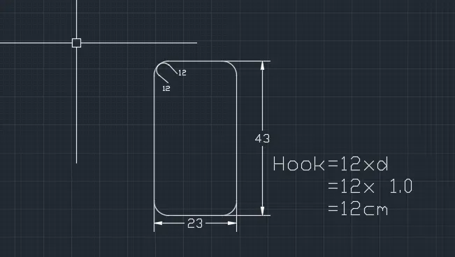
- Take line and draw retangle with 23 x 43 mm
- use fillet command to fillet the corner with 4mm radius.
- Use Text command to text the written content.
STEP-6
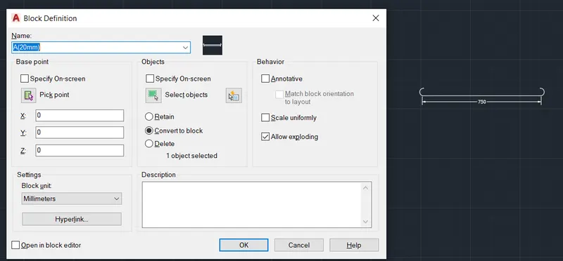
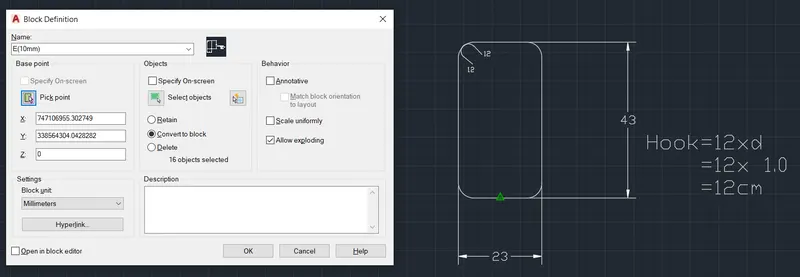
CREAT BLOCK
- Now go to the final part of the drawing
- select single autocad drawing object than enter block command in the command bar.
- Now put the name of the particular block name in the name box
- pik up point of this object
- than go to description part and describe about this
- now press okk
- this object is converted in to the block.
- all types of block of the symbol is drawn and attached with this project.
CREAT BLOCK
CREAT BLOCK
CREAT BLOCK
CREAT BLOCK
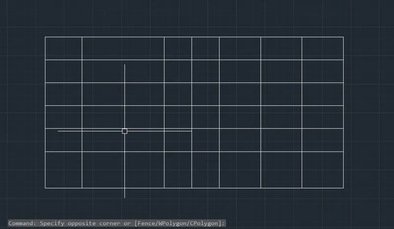
CREAT TABLE:
STEP-7
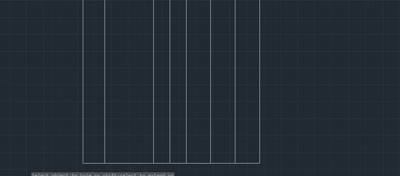
- With the help of line command
- draw a line horizontl and verical
- start taking ofset of vertical line
- take offset 400mm
- again take offset 900 mm
- again take offset 300mm
- again take offset 300mm
- again take offset 450mm
- again take offset 450mm
- again take offset 500mm
STEP-8
- With the help of line command
- start taking offset from horizontal line
- take offset 400mm
- again take offset 250 mm
- again take offset 250mm
- again take offset 250mm
- again take offset 250mm
- again take offset 250mm
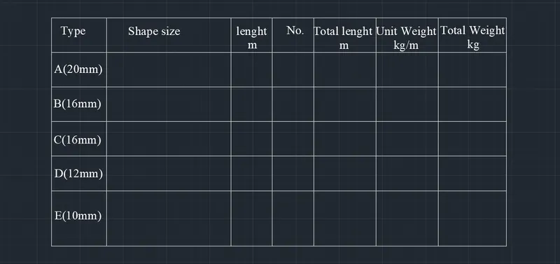
STEP-9
- Use text command to written all the given content in the table
- for writing part set units and height of text.
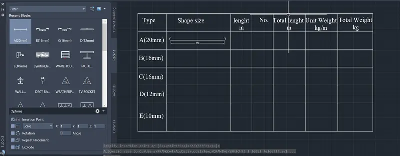
STEP-10
INSERT BLOCK
INSERT BLOCK
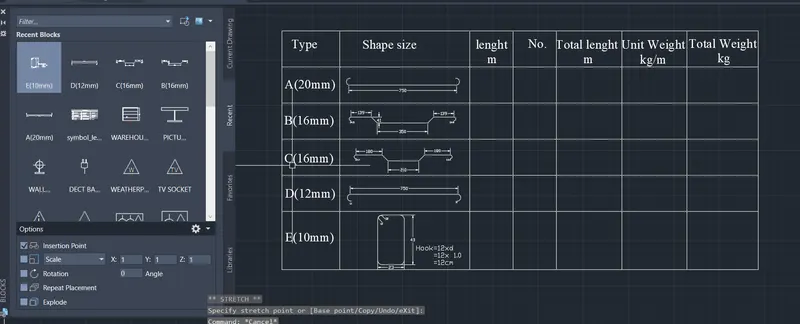
RESULT:
: Given DRAWINGS as a block with name given are completed according to given templets after maling drawing i had to converted into block than inserted into the table . the autocad drawing link have attached with result. and screenshots are also attached.
AUTOCAD DRAWING LINK:
https://web.autocad.com/acad/me/sid/shares/drawings/177fd18b-3665-49c9-957a-b0bee098a586/editor
https://web.autocad.com/acad/me/sid/shares/drawings/177fd18b-3665-49c9-957a-b0bee098a586/editor
RESULTANRT DRAWING