Creation of geometries by Coordinate system methods using AutoCad
Question:
Create the geometries from P1 to P2 using all the coordinates system methods. You need to use the Line tool to create the geometries. Where required you need to use the circle tool.
Please read the drawings and find out the missing dimensions before working on the sketches
Answer:
AIM:
(A) Creat the geometries from P1 to P2 using all the coordinate system methods and also using line tool to find the missing dimension.
(B) Civil related problme: Draw the profile and the trusses using any coordinate system methods using given dimensions as refrence.
INTRODUCTION: Coordinate system is three types
- Absolute coordinates
- Relative coordinates
a) Relative rectangular Coordinate
b) Relative polar Coordinate - and last is direct Distance entry.
Absolute Coordinate:
absolute cooordinate system when ever you mention any point with respect to the origin point (0,0) the coordinate of origin point (0,0).
Relative Coordinate:
After first point entrered your next points be entered by specifying the next coordinate relative from the first point the relative coordinate startd with symbol '@' tell AutoCAD is wal a relative coordinate. USing relative coordinate , points entered by typing @x ,y [Enter]
We Can use the Command:
- Line Command
- Circle Command
- Text Commnd
PROCEDURE:
Provide Drawing:
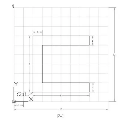
For Drawing (P1)
(a) Absolute coordinate system:
- Click on AutoCAD application and open this application
- Type QNEW in the command bar and enter
- Select default setting as imprerial
- In default sttting click on use wizard and in that advance setting se unit as decimal and precision as 0 and pres next .
- Set angle as decimal degree and precision 0 and press enter
- Set angle measure and EAST and press next
- Set angle direction as Counter- clockwise and press next
- Set area b providing lenght as 10 and width 10
- Press finish
- From home tab click on line
- Specify first point in command bar (2,1)
- Specify next point as (8,1)
- Specify next point (8,2)
- Specify next point (3,2)
- Specify next point (3,6)
- Specify next point (8,6)
- Specify next point (8,7)
- Specify next point (2,7)
- Click on close in command bar
- The Geometry is done.
(b)Relative Rectangular Coordinate:
- Click on AutoCAD application and open this application
- Type QNEW in the Command bar and press enter
- Select Default setting as imperial (feet & inches)
- In default setting click on use wizard and in that advance setting set unit as decimal and precision as 0 and press Next
- Set angle measure as EAST and press next
- Set angle directtion as counter - clockwise and press next
- Set area by providing lenght as 10 ad width 10
- presh finis.
- From home tab click line
- Specify first point in command bar (2,1)
- Specify next point @6,0
- Specify next point @0,1
- Specify next point @-5,0
- Specify next point @0,4
- Specify next point @5,0
- Specify next point @0,1
- Specify next point @6,0
- Click in close in command bar
- The Geometry is done.
(C) Relative Polar Coordinate:
- Click on AutoCAD and open this aplication
- Type QNEW in the cammand bar and enter
- Select default setting as imperial (feet and Inches)
- In default setting click on use wizard and in that advance set unit as decimal and preicision as 0 and press next.
- Set angle as decimal degree and precision 0 and press next
- Set angle measure as EAST and press next
- Set angle direction as counter - clockwise and press next
- Set area by providinng Lenght as 10 width 10
- press finish
- From Home tab click on line.
- Specify first point in command bar (2,1)
- Specify next point @6<0 (Towards East)
- Specify next point @1<90 (Towardds North )
- Specify next point @5<180 (Towards West)
- Specify next point @4<90 (Towards North)
- Specify next point @5<0 (Towards East)
- Specify next point @1<90 (Towards North )
- Specify next point @6<180 (Toward West)
- Click on Command bar
- The Geometry is done.
(d)Direcct Distance Entry:
- Click on AutoCAD and open this aplication
- Type QNEW in the cammand bar and enter
- Select default setting as imperial (feet and Inches)
- In default setting click on use wizard and in that advance set unit as decimal and preicision as 0 and press next.
- Set angle as decimal degree and precision 0 and press next
- Set angle measure as EAST and press next
- Set angle direction as counter - clockwise and press next
- Set area by providinng Lenght as 10 width 10
- press finish
- From Home tab click on line.
- Specify first point in command bar (2,1)
- Specify the next point as 6 (keep curser towards east)
- Specify the next point as 1 (keep curser towards North)
- Specify the next point as 5 (keep curser towards west)
- Specify the next point as 4 (keep curser towards north)
- Specify the next point as 5 (keep curser towards east)
- Specify the next point as 1 (keep curser towards nort)
- Specify the next point as 6 (keep curser towards west)
- Click on Close COmmand
- The Geometry is done .
For Drawing (P2)
Provide Drawing:
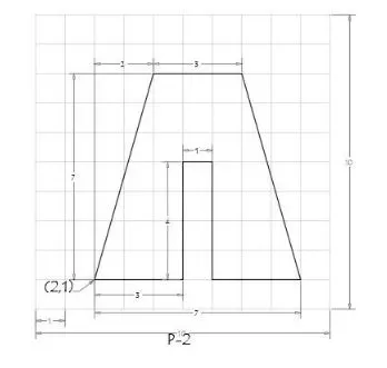
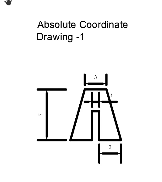
(a) Absolute coordinate system:
- Click on AutoCAD application and open this application
- Type QNEW in the command bar and enter
- Select default setting as imprerial
- In default sttting click on use wizard and in that advance setting se unit as decimal and precision as 0 and pres next .
- Set angle as decimal degree and precision 0 and press enter
- Set angle measure and EAST and press next
- Set angle direction as Counter- clockwise and press next
- Set area b providing lenght as 10 and width 10
- Press finish
- From home tab click on line
- Specify first point in command bar (2,1)
- Specify next point as (5,1)
- Specify next point (5,5)
- Specify next point (6,5)
- Specify next point (6,1)
- Specify next point (9,1)
- Specify next point (7,8)
- Specify next point (4,8)
- Click on close in command bar
- The Geometry is done.
b)Relative Rectangular Coordinate:
- Click on AutoCAD application and open this application
- Type QNEW in the Command bar and press enter
- Select Default setting as imperial (feet & inches)
- In default setting click on use wizard and in that advance setting set unit as decimal and precision as 0 and press Next
- Set angle measure as EAST and press next
- Set angle directtion as counter - clockwise and press next
- Set area by providing lenght as 10 ad width 10
- presh finis.
- From home tab click line
- Specify first point in command bar (2,1)
- Specify next point @3,0
- Specify next point @0,4
- Specify next point @1,0
- Specify next point @0,-4
- Specify next point @3,0
- Specify next point @-2,7
- Specify next point @-3,0
- Click in close in command bar
- The Geometry is done
(C) Relative Polar Coordinate:
- Click on AutoCAD and open this aplication
- Type QNEW in the cammand bar and enter
- Select default setting as imperial (feet and Inches)
- In default setting click on use wizard and in that advance set unit as decimal and preicision as 0 and press next.
- Set angle as decimal degree and precision 0 and press next
- Set angle measure as EAST and press next
- Set angle direction as counter - clockwise and press next
- Set area by providinng Lenght as 10 width 10
- press finish
- From Home tab click on line.
- Specify first point in command bar (2,1)
- Specify next point @3<0
- Specify next point @4<90
- Specify next point @1<0
- Specify next point @4<270
- Specify next point @3<0
- Specify next point @7<106
- Specify next point @3<180
- Click on Command bar
- The Geometry is done.
(d)Direcct Distance Entry:
- Click on AutoCAD and open this aplication
- Type QNEW in the cammand bar and enter
- Select default setting as imperial (feet and Inches)
- In default setting click on use wizard and in that advance set unit as decimal and preicision as 0 and press next.
- Set angle as decimal degree and precision 0 and press next
- Set angle measure as EAST and press next
- Set angle direction as counter - clockwise and press next
- Set area by providinng Lenght as 10 width 10
- press finish
- From Home tab click on line.
- Specify first point in command bar (2,1)
- Specify the next point as 4 (keep curser towards north)
- Specify the next point as 1 (keep curser towards east)
- Specify the next point as 4(keep curser towards south)
- Specify the next point as 3 (keep curser towards east)
- Specify the next point as 7 (keep curser towards east)
- Specify the next point as 3 (keep curser towards west)
- The Geometry is done .
Next Provide Drawing:
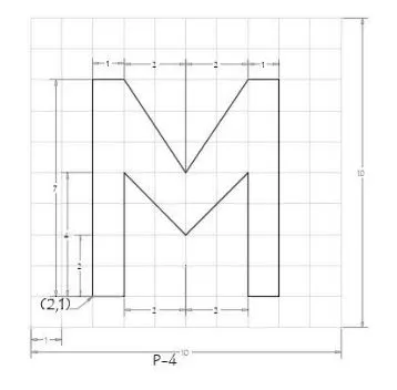
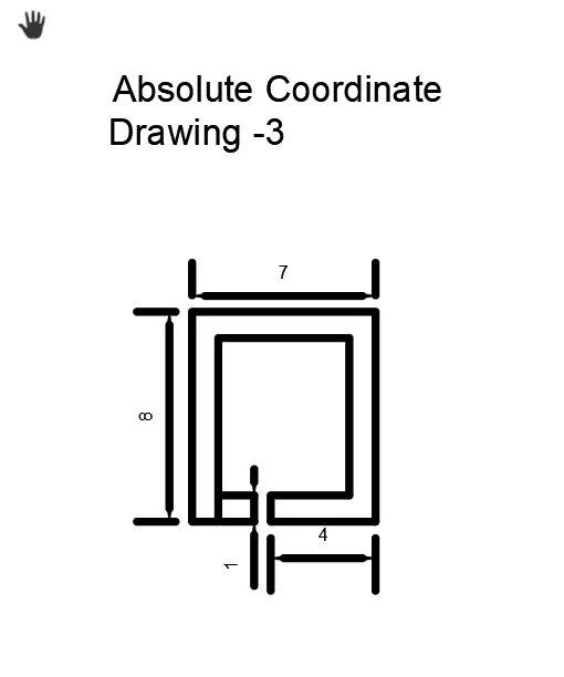
Using Absolute Coordinate system:
- Select Line tool from ribbon or Type line command in the Command bar
- Specify the first point (2,1)
- Specify the first point @1,0
- Specify the first point@0,7
- Specify the first point@5,0
- Specify the first point@0,-6
- Specify the first point @-3,0
- Specify the first point @0-1
- Specify the first point @4,0
- Specify the first point @0,8
- Specify the first point@-7,0
- Click on Close command line
Next Provide Drawing:
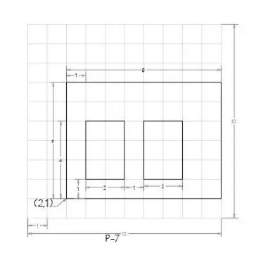
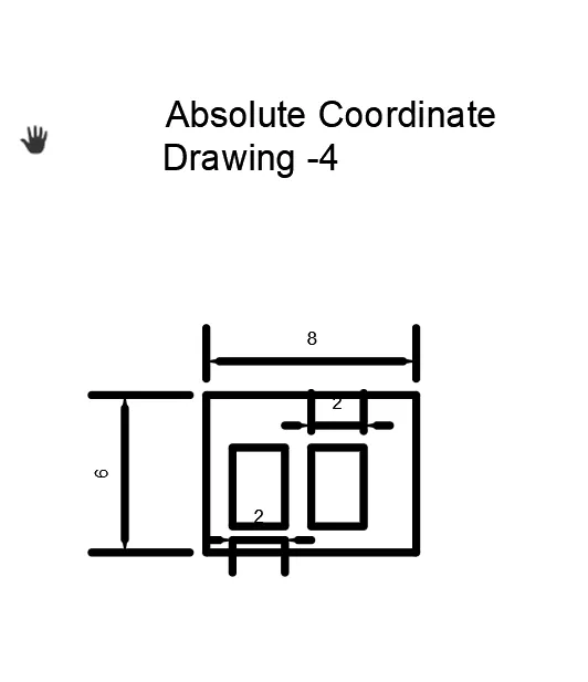
Using Absolute Coordinate system:
- Select line tool from ribbon or type line command in command bar
- Specify first point (2,1)
- Specify next point (10,1)
- Specify next point (10,7)
- Specify next point (2,7)
- Click On CLOSE command line
- Select LINE tool from ribbon or type line command in command bar
- specify first pont (3,2)
- Specify next point (5,2)
- Specify net point (5,5)
- Specify next point (3,5)
- Click on CLOSE in command line
- Select Line Tool from ribbon or type line command in command bar
- specify first point (6,2)
- Specify next point (8,2)
- Specify next point (8,5)
- Specify next point (6,5)
- Click on CLOSE in command line.
Next Provide Drawing:
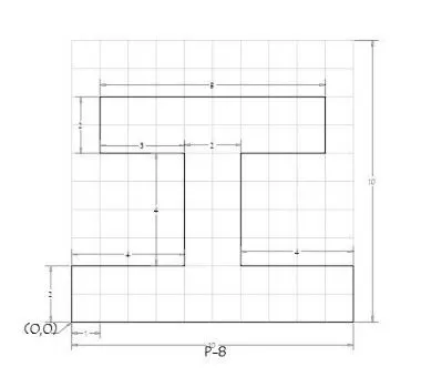
Using Rectangular Coordinate system :
- Select Line Tool from Ribbon or type line command in command bar
- Specify first point (0,0)
- Specify next point @10,0
- Specify next point @0,2
- Specify next point @-4,0
- Specify next point @0,4
- Specify next point @3,0
- Specify next point @0,2
- Specify next point @-8,0
- Specify next point @0,-2
- Specify next point @3,0
- Specify next point @0,-4
- Specify next point @-4,0
- Click on CLOSE in command bar
Next Provide Drawing:
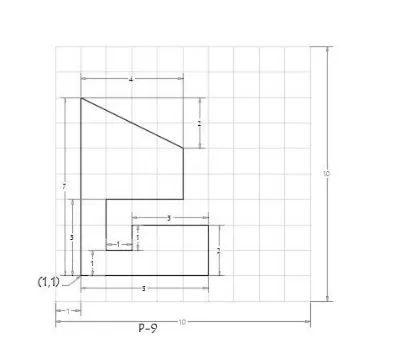
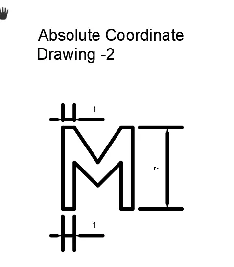
Using absolute Coordinate System :
- Select LINE tool from ribbon or type line command in command bar
- Specify First point (1,1)
- Specify next point (6,1)
- Specify next point (6,3)
- Specify next point (3,3)
- Specify next point (3,2)
- Specify next point (2,2)
- Specify next point (2,4)
- Specify next point (3,4)
- Specify next point (5,6)
- Specify next point (1,8)
- Click on CLOSE in command line
Next Provide Drawing :
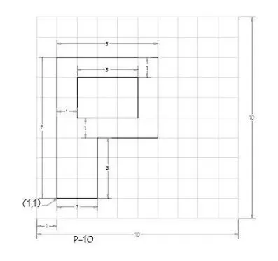
Using Relative Polar Coordinate system;
- Select line tool from ribbon
- Specify first point (1,1)
- Specify next point @2<0
- Specify next point @3<90
- Specify next point @5<180
- Specify next point @4<90
- Specify next point @5<180
- Click close in Commnad line
- select line from ribbon
- Specify next point @3,2
- Specify next point @2<90
- Specify next point @3<180
- Click on Close in Command line
Civil Related Problems
Draw the profile and the trusses using any coordinate system methods. The dimensions are there for references.
Civil Realated Problem-Provide Drawing
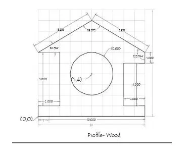
Using Direct Distance Method:
- Select line from Ribbon
- Specify first point (0,0)
- Specify next point lenght as 10 (keep cursur towards east )
- Specify the next point as 1 (keep curser towards north)
- Specify the next point as 2 (keep curser towards west)
- Specify the next point as 4 (keep curser towards north)
- Specify the next point as 2 (keep curser towards esat)
- Specify the next
- point lenght as 831 at an angle < 149.036 from +ve x-direction (keeping polar tracking on)
- Specify next point lenght as 2 towards east
- Specify next point length 5 towards south
- Specify next point length 2 towards east
- Click CLOSE in command line
- Select the circle tool by entering CIRCLE command in command bar
- specify center point (5,4)
- Specify radius of circle as 2
Next Provide Drawing :
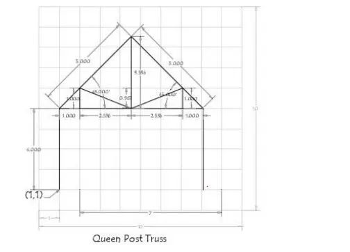
Using relative coordinate system 6264424960
- Type line in command bar and enter
- Specify first point (1,1)
- Specify next point @1,0
- Specify next point @0,4 and lets consider as point 1
- Specify next point @3.536,3.536 and lets consider as point 2
- Specify next point @3.536,-3.536 and lets consider as point 3
- Specify next point @0,-4
- Press ESC to cancle the LINE command
- Select line tool again from ribbon
- joint point 1 and 3
- Press ESC to cancle the line command
- select line tool again from ribbon Specify point as (4.536,1)
- Specify next point @-2.536,1
- Specify next point @0,-1
- Press ECS to cancle the line cammand
- Select line again from ribben.
- joint 2 and 4 .
- Press ESC to cancel the LINE command
Next Drawing Provide:
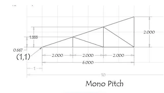
Using Absolute coordinate system:
- Select line from ribbon or type LINE command in command bar:
- Specify first point (1,1)
- Specify first point (7,1)
- Specify first point (7,3)
- Click on close in command line
- Slect line from Ribbon
- Specify first point (3,1)
- Specify first point (3,1.667)
- Specify first point (5,1)
- Specify first point(5,2.33)
- Specify first point(7,1)
- Press ESC to cancel the line LINE command.
RESULT:
Drawing MAde by me: