Creating a Floor plan, Footing detail and Isometric view using AutoCad
QUESTIONS :- Creating a Floor plan, Footing detail and Isometric view using AutoCad
ANSWER:-
AIM: Creating a Floor plan , Footing Details And Isometric view using Autocad
OBJECTIVE : objective of this project is to touch with the command of autocad Software
commands name :
- LINE
- RECTANGLE
- CIRCLE
- POLYLINE
- EXTEND
- TRIM
- FILLET
- CHAMFER
- ROTATE
- MIRROR
- COPY
- ARRAY
- DIMENSION
- ERASE ETC.
INTROCDUCTION:
- AUTOCAD
- Floor plan
In A Architectural and Buiding engineering , a Floor plan is a technical drawing to scale , Showing a view from above , of the relationship between rooms , spaces , traffic patterns and other physical features at one level structure. - Footings:
Footings are important part of foundation construction . they are typically made of concrete with rebar reinforcement thst has been poured into an exacavated trench . The purpose of footings is to support the foundation and prevent settling . - Isometric views :
Isometric projection is a visually representing three - dimentional objects in two dimentions in technical and engineering drawings . in isometric drawing iso means same and the metric meaning is measurement.
PROCEDURE:
FOOTING DETAILS
Cross Setional of Load bearing wall showing foundation details.
Used Command:
- LINE
- RECTANGLE
- TRIM
- OFFSET
- DIMENTIOM
- TRIM
PROCEDURE:
- Type rec in the command bar to creat rectangle.
- Specify first point. (5,5)
- Specify Second point of rectangle (@0.90,0.45)
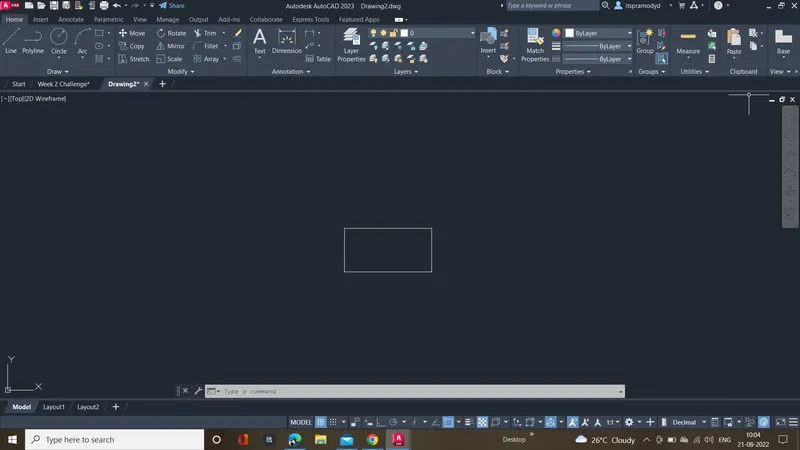
- Creating Another rectangle
- Specify First corner point which is 0.15 unit from the starting point of first rectangle
- Enter the lenght = 0.6 ,width= 0.4
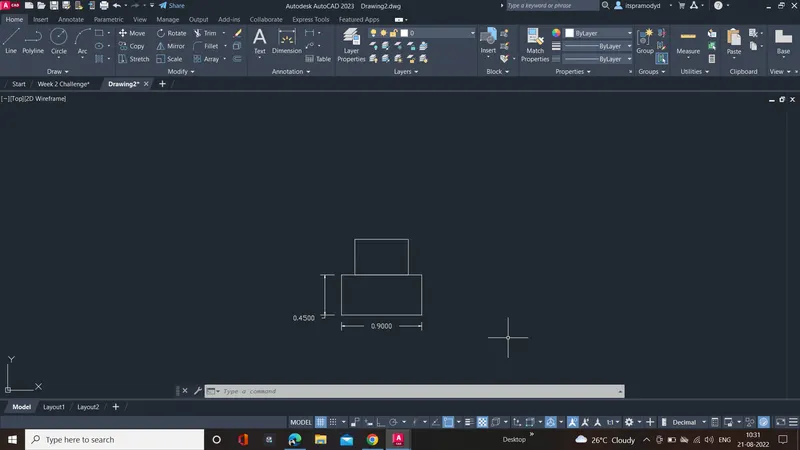
- Creating Third rectangle
- Specify First corner point which is 0.05unit from the starting point of first rectangle
- Enter the lenght = 0.5 ,width= 0.3
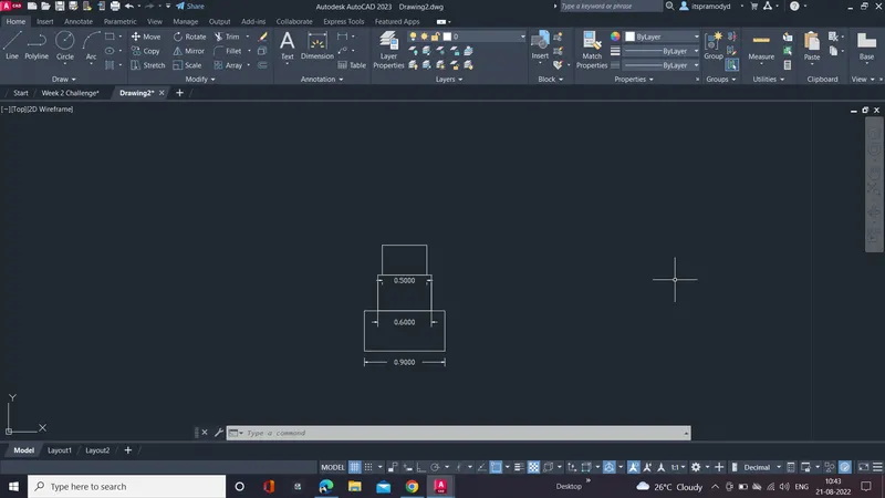
- Creating Fourth rectangle
- Specify First corner point which is 0.05unit from the starting point of first rectangle
- Enter the lenght = 0.4 ,width= 0.6
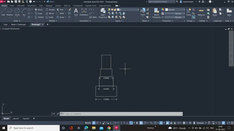
- Creating Fifth rectangle
- Specify First corner point which is 0.05unit from the starting point of fourth rectangle
- Enter the lenght = 0.3 ,width= 01
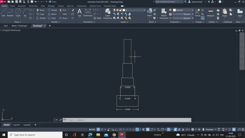
- Trim the unwanted line with the help of trim command.
- using the dimention tool show the all dimention.
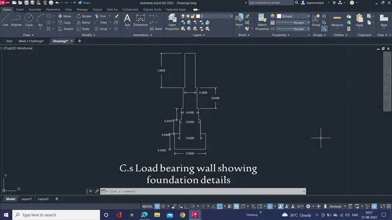
Result : The C/S of load bearing wall foundation details is shown.
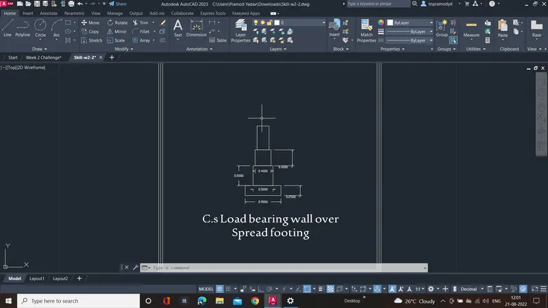
AIM : To draw cross sectional of wall over footing .
Procedure :
Steps:
- Creat rectangle by using rec commnand.
- Soecify first point as (5,5)
- Second point by lenght 0.9
- width = 0.25
- Creat another rectangle "REC" command
- first point is 0.2 unit from the starting point of first rec.
- Enter the lenght = 05. , width = 0.4 unit
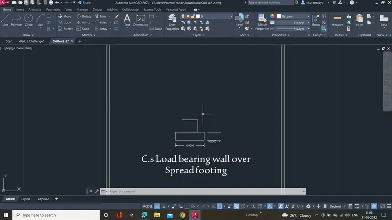
- Creat the third rectangle with the help of "REC" command
- first point is 0.05 unit from the second rectangle
- Enter the lenght =0.4 width = 0.4
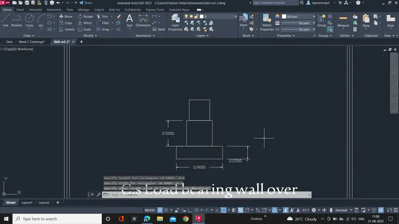
- Creat the fourth rectangle with the help of "REC" command .
- Specify firth point at the distance of 0.05 from the third third rectangle.
- Give the lenght as 0.3 and width as 0.6.
- Line is drawn from the corner of third rectangle using command L
- Move cursor downward and give value 0.15 unit and right and give lenght 1.15
- from last point of line this line 0.15 verticaly and 0.3 horizontally
- again vertically 0.15 , horizontlly 0.3
- again vertically 0.15 , horizontlly 0.3
- again vertically 0.15 , horizontlly 0.3
- Draw another rectanle
- Draw another rectanlge above fourth rectangle width the help of REC command
- Lenght = 0.3 , Width = 0.05
- Draw fifth rectangle With help of REC command.
- first point is start from fourth rectangle
- lenght = 0.3 width 1 unit
- Erase the unwanted line .
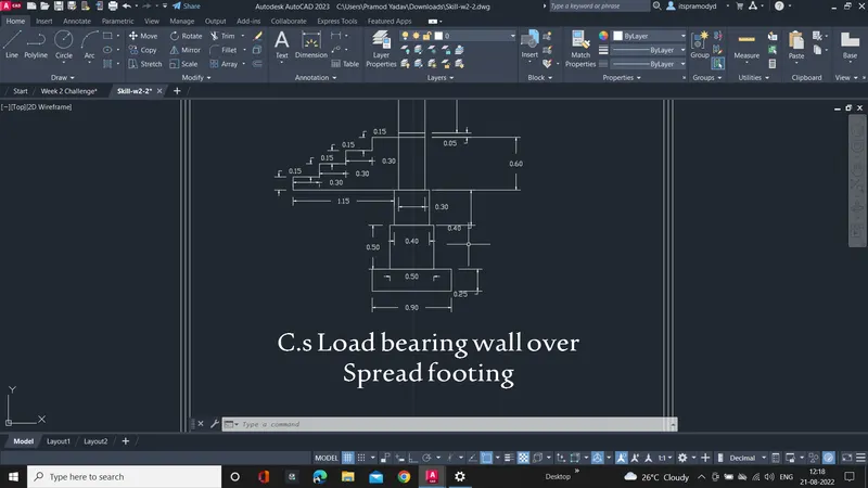
Result : The Cross section of load bearing wall over spread footing is drawn.
Line Diagram of 2 BEDROOM building.
AIM: To draw line diagram of 2 bedroom building
Command Used :
- Line
- Rectangle
- Offset
- Trim
- Dimention
Procedure:
Step-1
- Creating bedrooom 8.2 x 3.6 from rectangle command.
- Draw an offset using the command 'o'
- In the command bar enter O and specify the dis. of 3.6 unit from the right bottom end.
- Draw an offset using the command O at a dis. 4.2 unit from the right bottom end.
- Extend the two line in the bottom and in the top
- Draw an offset distance of 0.3 between the two line to bottom side .
- Repead the same step and creat two offsets
- Trim Unnecessary lines.
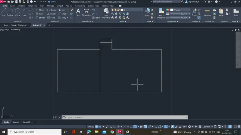
Step -2
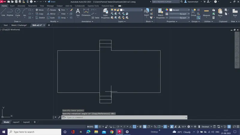
- With the help copy command copy the object
- than replace it from second side
- and select the oobject and rotate acording to the figure
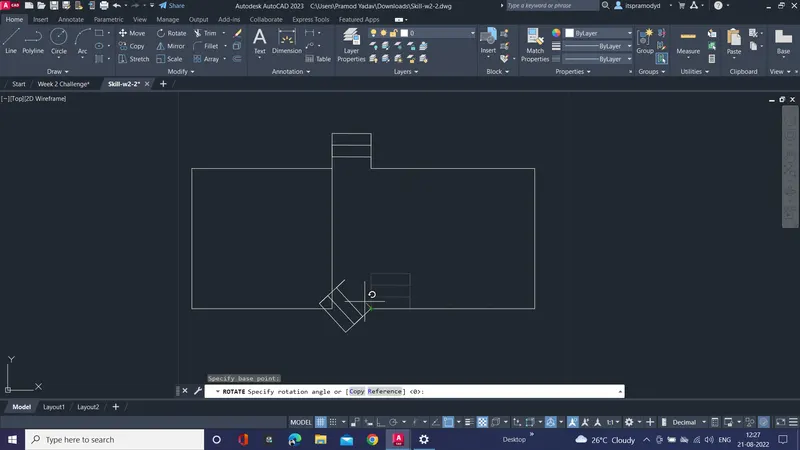
Step-3
- than replace it from second side
- and select the oobject and rotate acording to the figure
Step -4
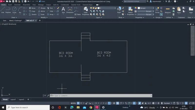
- with the help of text Command wright the name and size of the bedroom
- and from dimenttional command measure the all dimention and show
Step -5
- and from dimenttional command measure the all dimention and show
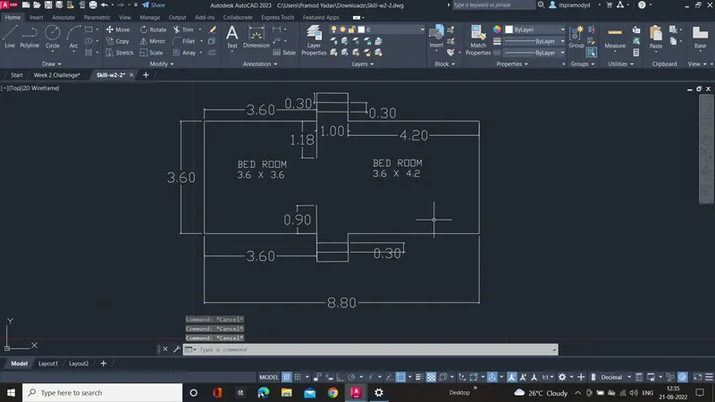
Result : Complete the floor plan in AutoCAD .
ISOMETRIC VIEW OF STEPS :
AIM : Creating Isometric view of Steps in the autocad .
Command Used :
- Line
- Isometric Plan
Proedure :
- To work with Isometric view Firstly Snap mood off , Grid off Put ISometric Snap on .
- Ortho mode is on.
- for star the drawing firstly from isometric drafting select iso-plane left
- for select the isometric plan we can press F5
- Give command 'L' and moving the cursor to -x direction left give unit 1
- Moving the cursor to +y direction top , give the unit 0.15.
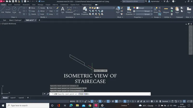
- Moving the cursor x direction again 1 unit and -y to dire. unit 0.15
- change the isometric drafting to iso plan top
- Move the cursor to back and give 0.3 unit from the last down point
- Move the cursor right direction.
- Move the cursor front and give 0.3 unit.
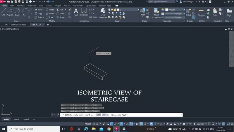
- Change the isometric drafting to iso plan right .
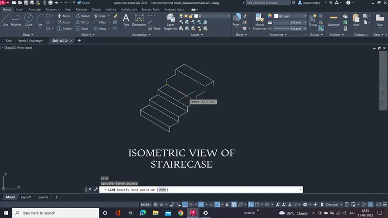
- With the help of this command try to make same step we can also make using copy command to make steps.
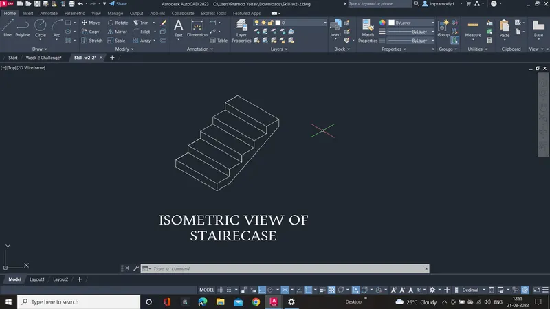
- show all the dimention.
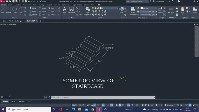
Result : complete the isometric view of step shown in figure.
ISOMETRIC VIEW OF GABLE WALL
AIM: To draw the isometric view of gable wall.
Command Used :
- Line
- Isometric Plan
Proedure :
- To work with Isometric view Firstly Snap mood off , Grid off Put ISometric Snap on .
- Ortho mode is on.
- for star the drawing firstly from isometric drafting select iso-plane left
- for select the isometric plan we can press F5
- Give command i and moving the cursor to right give 1 unit
- Pointing the cursor upward give 3 unit
- Dra 0.3 unit to left and 3 unit downwards and 0.3 unit to left .
- Using ISometric right take line command and draw line upwards of 2.42 unit from the starting pint of starting .
- Draw unit towards the right and 2.42 using unit downwards.
- Using isimetric left again usinf line command draw 0.3 unit to left side and draw 0.3 unit to left side and draw a line which intersect the top line .
- using isometric right with the line command draw 1 unit to right side and 0.3 unit upword
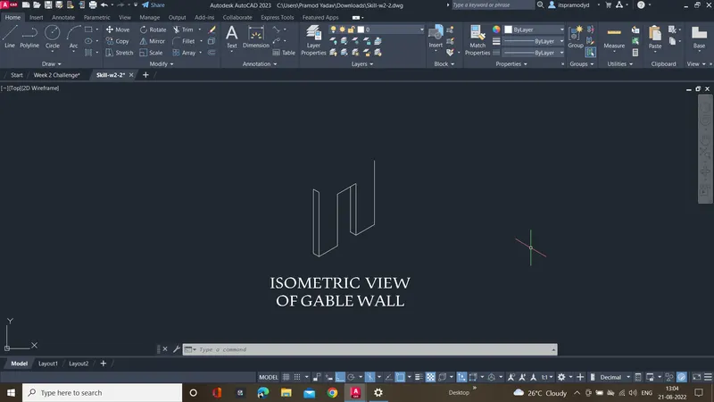
- By using the line command draw a line from bottom left corner @1.5 unit and extend line 4 unit upward i.e total 3.25 from bottom .
- With ortho off draw a line between the corner of left side and the projected line done.
- Draw it to the other also till it meets the right corner
- Draw the verticle line with ortho on @0.3 and join the verticle line using line from left and right end same as in the step 5 remove unwanted lines by using erage command
- shown in the figure the Isometric view of gable wall
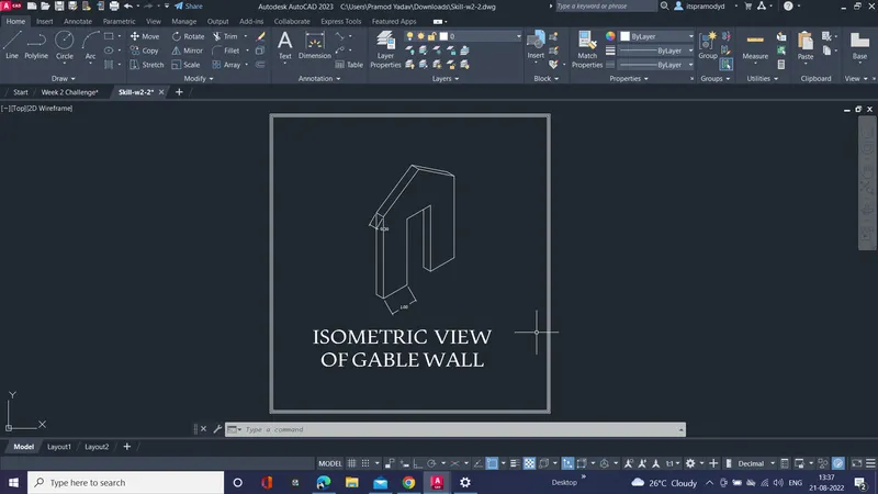
Result : Complete the drawing of the isometric view of gable wall.
CROOS SECTION OF AN ISOLATED FOOTING :
AIM: TO draw Cross Section of an isolated footings
Used command :
- Line
- offset
- Trim.
Procedure :
- Draw a line with command "L" and given 1 unit
- Give command "l" and give the relative coordinate as @0,0.15
- Next point @0.38,0.25
- Next pont @0.28,0
- Next point @0,-1.6
- Next point @ 0.36,-0.25
- Next point @ 0,0.15 or close
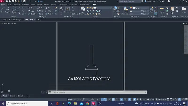
- Than Draw a offset with the command at a distance 0.04.from the bottom line to u words
- Gie the commad of "o" and select the object and give the offset distance 0.04.
- Do the same at the right and left bottom end .
- Trim the unwanted lines.
- Give offset 0.2 unit from the top line
- Give command o and select the object - give the offset distance as 0.2 -select multiple option a 9 such lines
- Trim the excess lines .
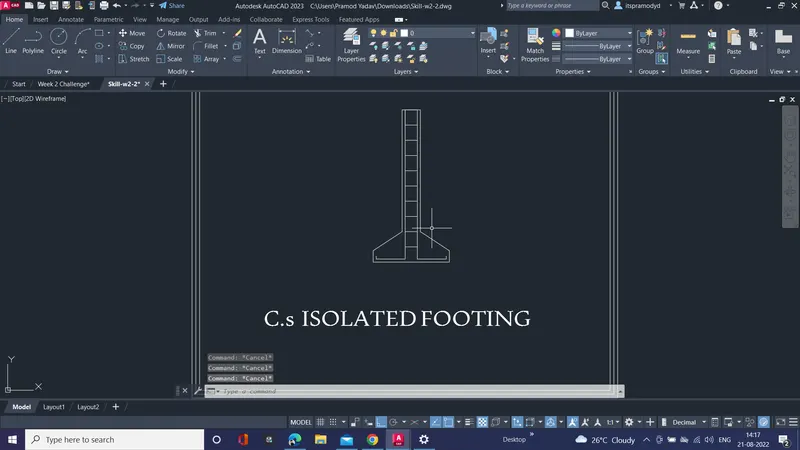
- With the help of Dimention Command give the dimention for every part of the figure.
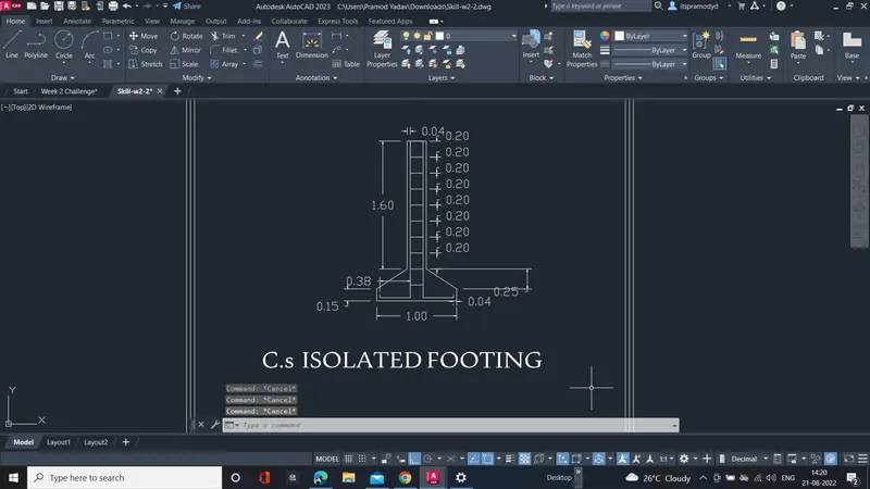
Result: Complete the drawing of Cross Section of an isolated footings
FINAL RESULT
RESULT : COMPLETED ALL THE FOLOEING FIGURES USING AUTOCAD
- FLOOR PLAN
- CROSS SECTION ISOLETED FOOTING
- ISOMETRIC VIEW OF GABLE VIEW
- ISOMETRIC VIEW OF STEP
- CROSS SECTION LOAD BEARING WALL OVER SPREAD FOOTING
--for check the details of any object, images are attached in this project.