Drafting of various geometries using Chamfer, Fillet tool in AutoCad
QUESTION:- Drafting of various geometries using Chamfer, Fillet tool in AutoCad
ANSWER: -
AIM: Drafting of following geometries using Chamfer , Fillet tool in Autocad Software .
INTRODUCTION:
- CHAMFER :
Chamfer are sloped or angled edges (usually 45 at or 60 ) of a design or part.
How to use: - - Take rectangle From tool bar or direct enter chamfer at command bar
- Click chamfer
- Entere First chamfer distance
- Enter Second Chamfer Distance. - FILLET:
Fillets descrives rounded corners of a design (or part).
- Take rectangle from riboon or type fillet at command bar.
- Click FILLET
- Enter fillet Angle
- Selcet First poinnt and than second point.
PROCEDURES:
DRAWING-1
TO DRAW THE FIGURE WE FOLLOW THE FOLLOWING STEPS : -
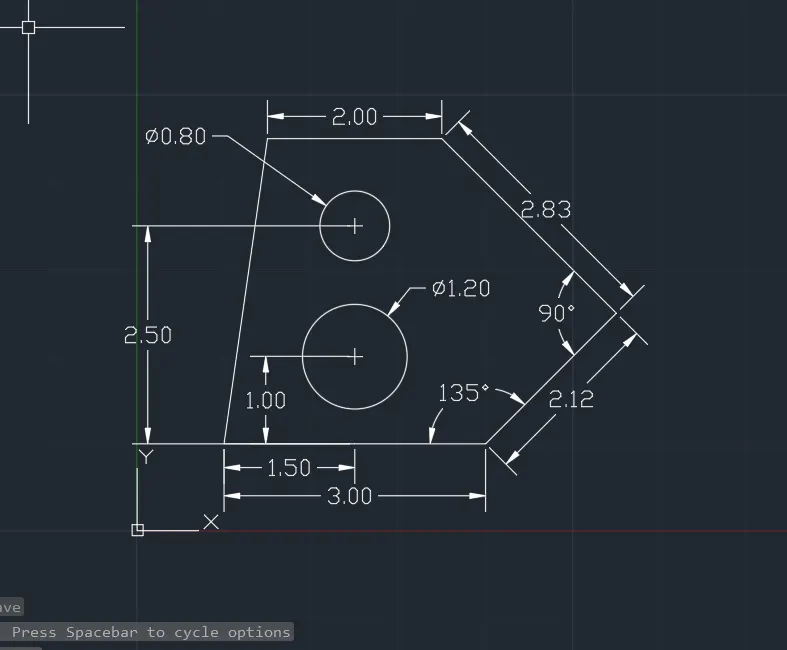
Set All units Decimal and set precision 0.00 , angle counter clock-wise .
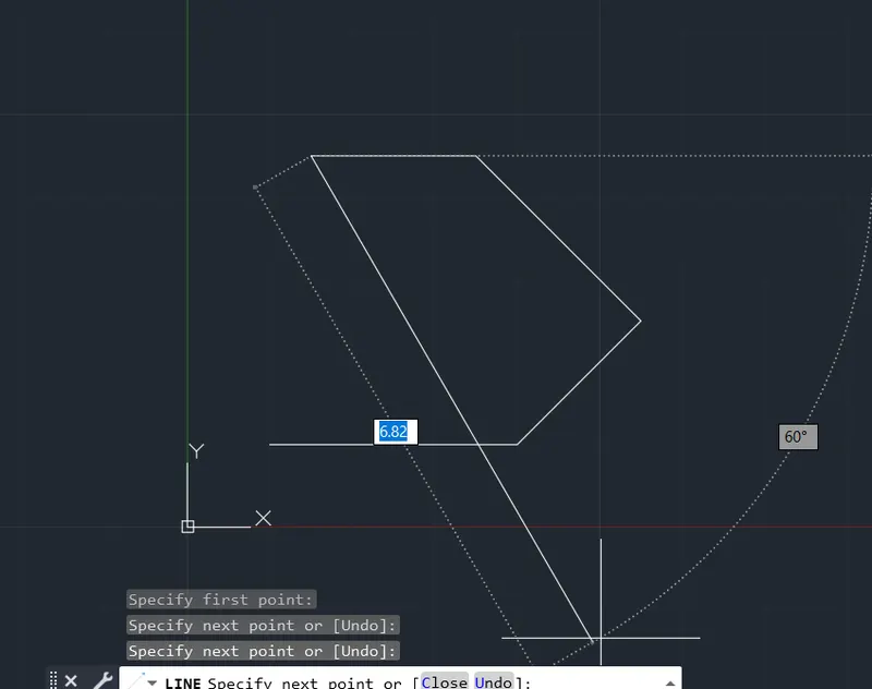
- Take Line from riboon - Home and Specify First point (1,1)
- take Distance 3 unit
- go upward for angle 135 degree , Take angle 45 from horizontal refrence line and distance 2.12 unit. ( Line Command)
- Go back-upward for 90 degree , take angle and dstance 2.83 from last point. (Line command )
- Go to parallel from first line with 2 unit . - (Line command)
- connnect the first point to the last point with the help of line command.
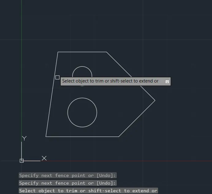
- Take perpendicular from first line, center point.
- Take offset with distance of 1 unit and 2,5 unit from first line.
- Draw Circle of 1.2 unit diameter at bottom intersection point and 0.80 diameter at upper intersection point.
- With the Dimention Command show the all dimentiion in the figure.
DRAWING -2
TO DRAW THE FIGURE WE FOLLOW THE FOLLOWING STEPS : -
Set all unit at Architectural format .
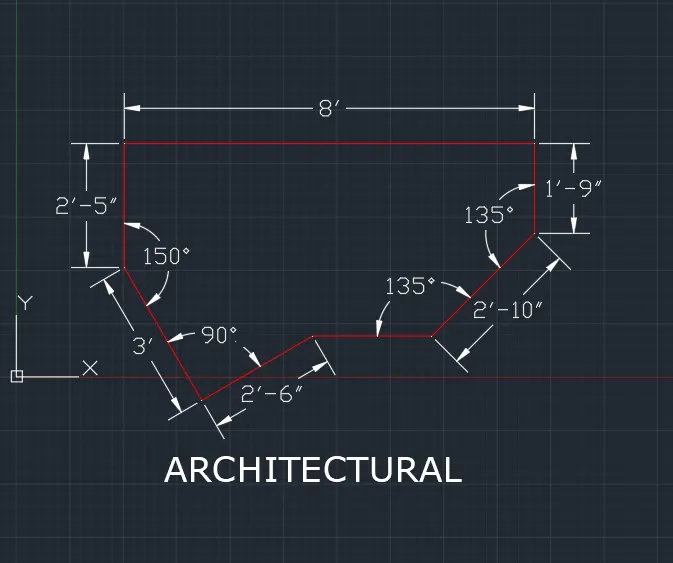
- Take line Command Speciy first point and make a line of 8' .
- Again take line Command and go to downward from the last point with 1',9" Distance.
- Again take line command and go dwonward with 2',10" distance and 135 degree angle
[Find the angle by assuming the pantagon. the some of angle of pantagone is 540 degree and in figure three angle 90 and one angle 135 so we can calculate the missing angle 540-(90+90+90+135)=135degree ] - Than again make a line and make an angle with 135 degree.
- Go to point first of line ,and draw a line with 2',5" distance dowward direction
- Take Line command and draw line with 3' unit with 150 degree angle
- make an angle 90 degree and connect a point with the distance of 2'6"
- the figure is shown in the
DRAWING -3
TO DRAW THE FIGURE WE FOLLOW THE FOLLOWING STEPS : -
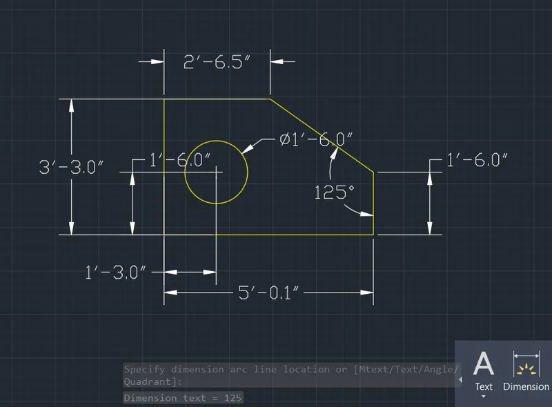
- Set All the units Engineering Formate and set precision 0.00
- Take A Line Command And specify first point (1,1)
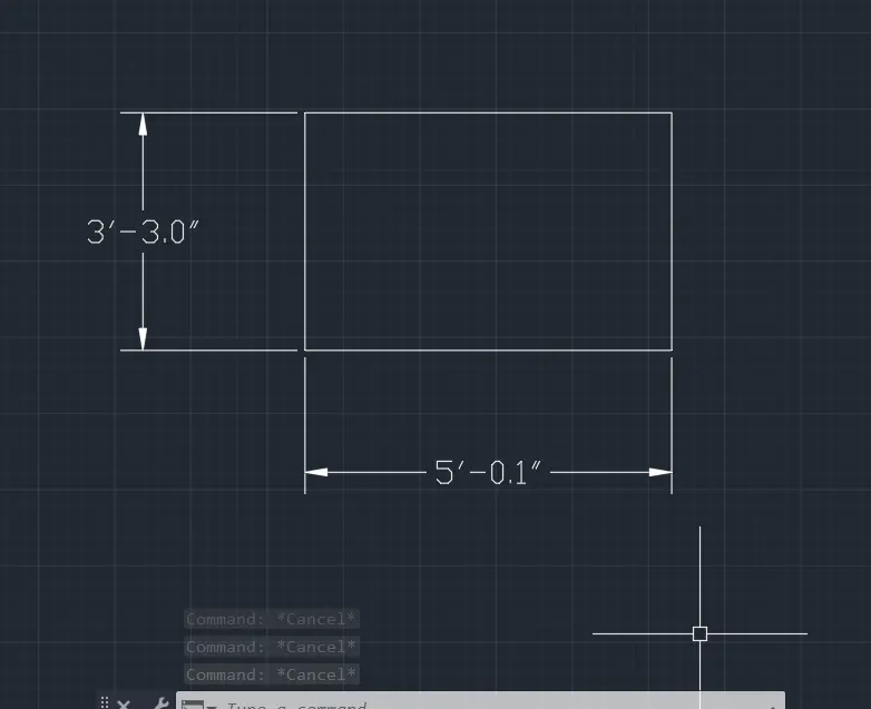
- Draw Rectangle by line command with 5'-01" Distance lenght .
- Specify next point width 3'-3.0" unit
- again take lenght 5'-0.1" and width 3'-3.0" units
- For Draw a circle to take offset of 1'-6.0" unit , from bottom hosrizontal line. and another offset of 1'-0" from vertical line of rectangle.
- Draw a circle from the center of intersecting line with 1'-6.0" diameter.
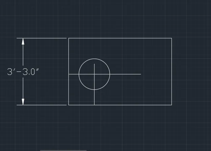
- With the help of Trim command erase the unwanted lines
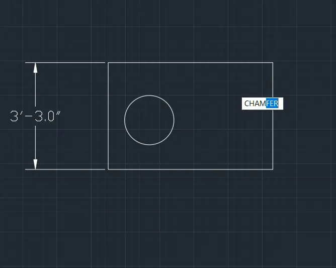
- For cut the corner take chamfer command with go distance
- Put the value of first chamfer distane = 1'-5.6"
- Put Second Chamfer distance = 1'-9.0"
- select first chamfer distance and sellect second chamfer distaance.
- we get chamfer shap of two lines.
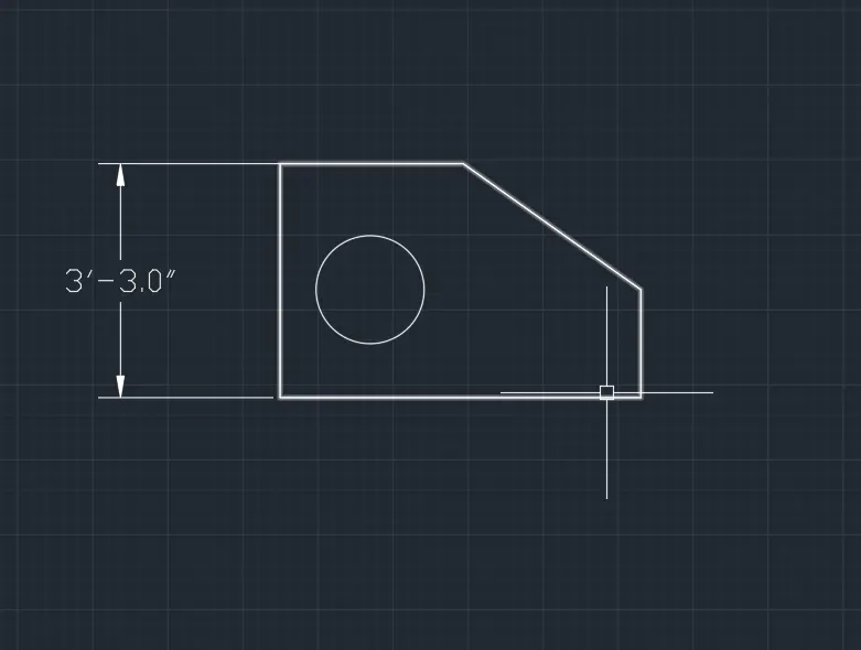
- With the Help of Dimention command show all the dimention for angular dimension use DIMD for Diameter and DIMRA for radius measurement
DRAWING NO -4
TO DRAW THE FIGURE WE FOLLOW THE FOLLOWING STEPS : -
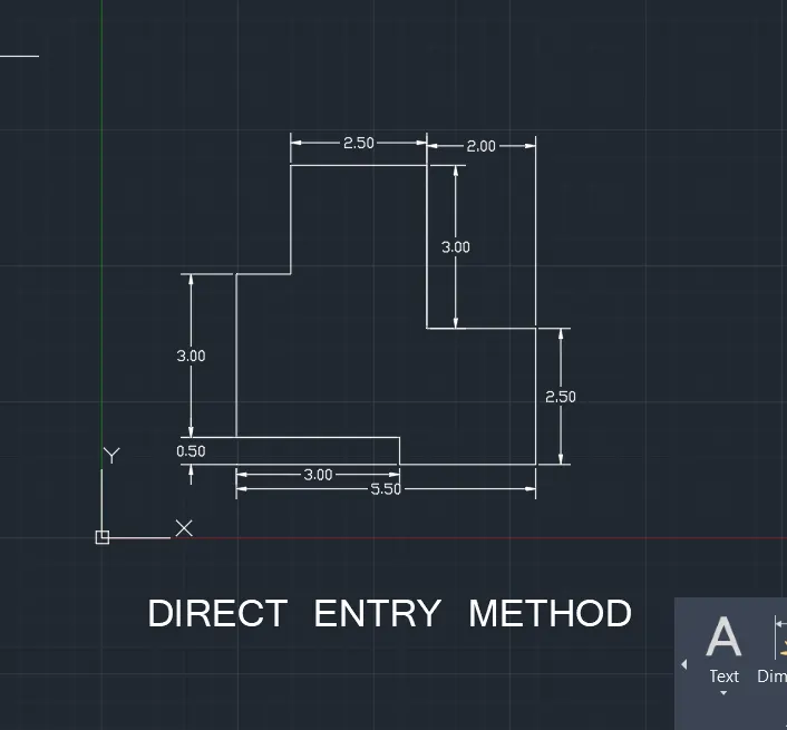
- Set All the units Decimal Format and set precision 0.00
- Take Line command specify first point( 1,1)
- Second point with distance of 3 unit .
- Go downward with 0.5 unit with line command
- Go to forward direction 2.50 unit.
- Go to upward direction (90 degree) with 2.50 unit.
- backward direction with 2.00 unit.
- Go upward direction 3.00 unit
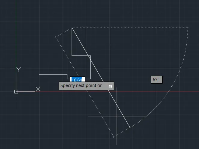
- Start with first point and go upward direction with 3.00 unit
- Draw a line 90 degree of angle from this point with forward direction.
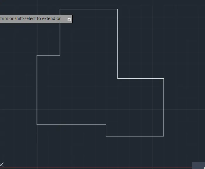
- Draw a line 90 degree of angle from last point of we drawn in dounward direction.
- Trim Unwanted lines.
- With the Help of Dimention command show all the dimention.
DRAWING NO - 5
TO DRAW THE FIGURE WE FOLLOW THE FOLLOWING STEPS : -
- Set All the units Decimal Formats and set precision 0.00
- Take A Line Command And specify first point (1,1)
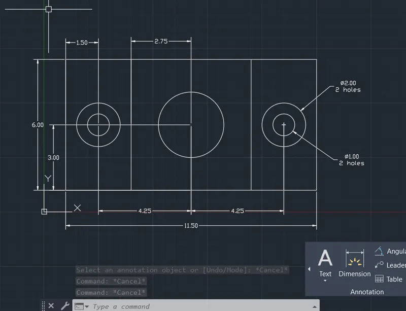
- Draw Rectangle by line command with 11.50 Distance lenght .
- Specify next point width 6.00 unit
- again take lenght 11.50 and width 6.00 units
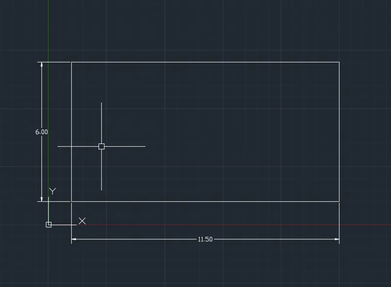
- Take Offset of 1.50 unit two times from width of rectangle.
- Take again offset 2.75 unit from last offset
- Again take 2.75 and 1.50 and 1.50 offset from last offset.
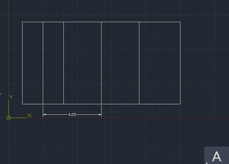
- Draw horizontal center line of the rectangle
- Take Circle Command draw a circle of dia = 1 unit and second circle dia 2 unit at same point from first intersecting point of offsect.
- Again take circle command draw circle with dia of 3.00 unit at geometric center.
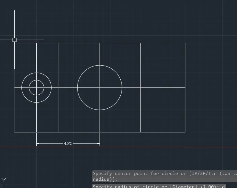
- Draw two circle at last intersecting point of offset draw circle with dia 1 unit and 2 unit .
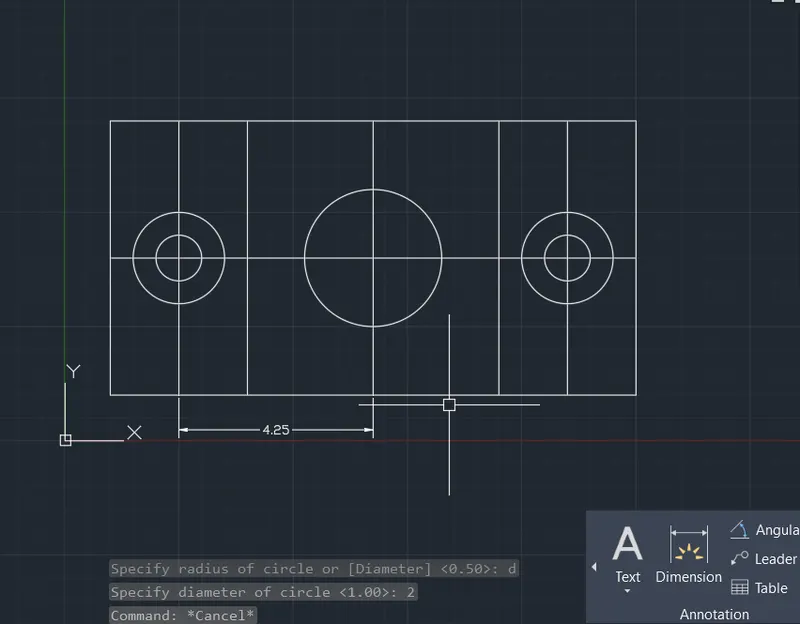
- With the help of trim or erase command trim the all unwanted lines .
- With the Help of Dimention command show all the dimention for angular dimension use DIMD for Diameter and DIMRA for radius measurement
DRAWING -6
TO DRAW THE FIGURE WE FOLLOW THE FOLLOWING STEPS : -
Shape -1
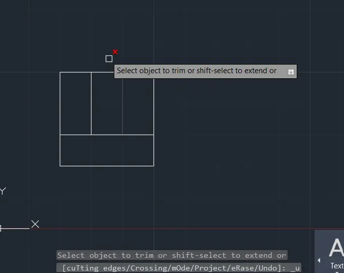
- Set the unit Decimal and set the precision 0.00
- Take Line Commmand specify first point (1,1)
- Specify Second point with distance 1.5 unit. forward direction.
- 1.5 unit upward Direction ,
- 1.5 backward direction from last point
- 1.5 unit downward Direction from last point
- Take offset 0.5 unit and take two times from first vertical line.
- 0.5 unit offset take from horizontal bottom line
- Trim unwanted lines.
Shape-2
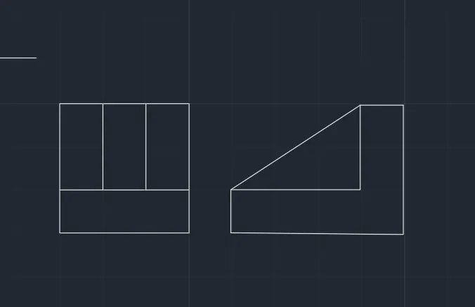
- Take line command specift first point and take distnce 2 unit X direction
- take perpendicular 1.5 unit from ending point of line.
- go 0.5 unit -X direction
- go 0.1 unit -Y directin
- go 0.15 unit -X direction
- go 0.5 unit -Y direction
- Connect the corner point of shape with help of line tool.
Shape-3
- Take line from toolbar specify first point go forward x direction 2 unit.
- Go 1.5 unit perpendicular from last point.
- Go -X direction with 2 unit.
- Go -Y direction withh 1.5 unit.
- Take Offset of 0.5 unit from bottom horizontal line.
- again take offset from last offset
- Again take offsetof 0.5 from perpendicular line .
- Trim Unwanted lines by using trim command.
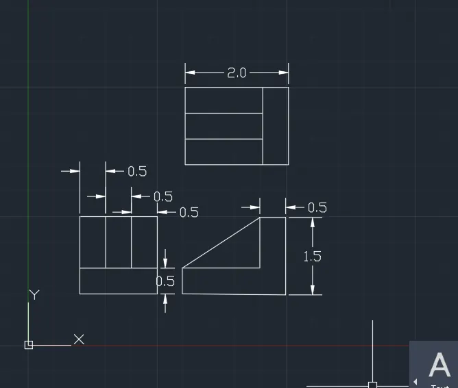
- With the Help of Dimention command show all the dimention.
DRAWING -7
TO DRAW THE FIGURE WE FILLOW THE FOLLOWING STEPS : -
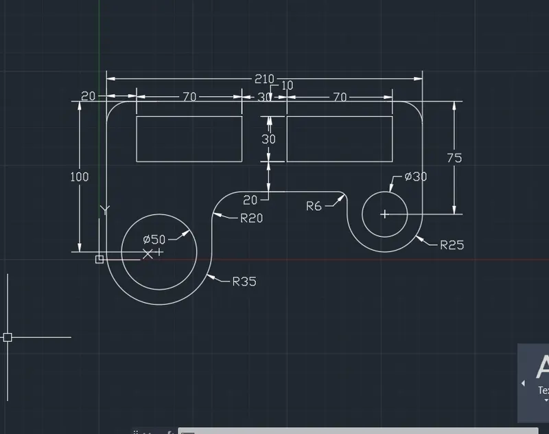
- Set the unit Decimal and set the precision 0
- Take Line Commmand specify first point (1,1)
- Specify Second point with distance 100 unit. upward (y)direction.
- Go 240 unit forward (x) Direction ,
- Go 75 downward (-y) direction from last point.
- Go 50 unit from backward (-X) direction.
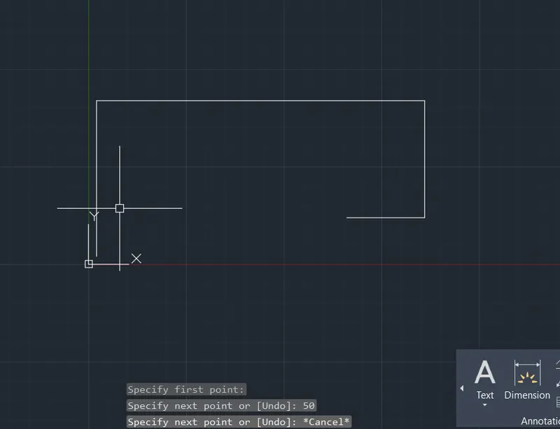
- Draw perpendicular from last point to the upward direction (Y)
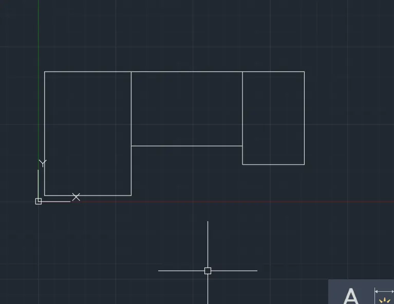
- Draw line from first point to x direction 70 unit and take perpendicular from this to upward y direction
- Take Offset 60 unit from upper line to downward .
- Take offset First perpendicular.
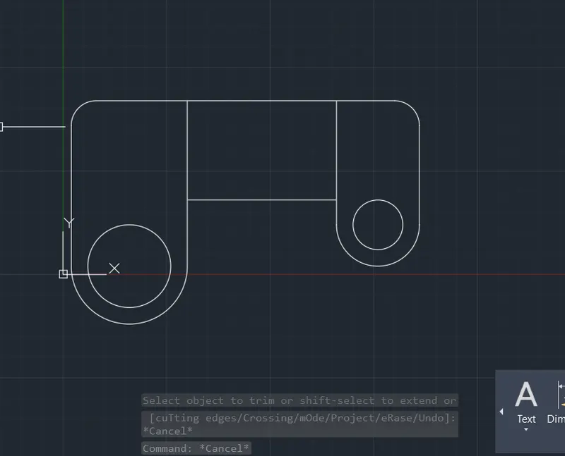
- Go to Arch Commaand and click on type of (Start ,center end ) draw a Arch botton horizontal center line with radius of 35 unit and make a circle of this point of 50 diameter.
- Draw another arch with the help of 25 unit radius. and make circle of this point of 30 unit diameter.
- for rounded the circle We use FILLET command
- Take FILLET from modify tool and put the radius 15 unit.
- click the upper corner point both side and fillet the corner
- Take horizontal offset of 10 unit from upper line.
- Again take offset of 30 unit.
- take vertical offset of 20 unit
- Again take offset 70 unit from last offset
- Again take offset 30 unit from the last point
- again take offset of 70 unit.
- Trim Unwanted lines .
- make fillet corners in the downside of the figure for fillet sureface take fillet command
- put the radius 20 unit and fillet the surface.
- make Another side fillet surface with the help of fillet command raius of 6 unit
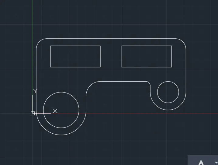
- With the help of trim or erase command trim the all unwanted lines .
- With the Help of Dimention command show all the dimention for angular dimension use DIMD for Diameter and DIMRA for radius measurement
DRAWING -8
TO DRAW THE FIGURE WE FOLLOW THE FOLLOWING STEPS : -
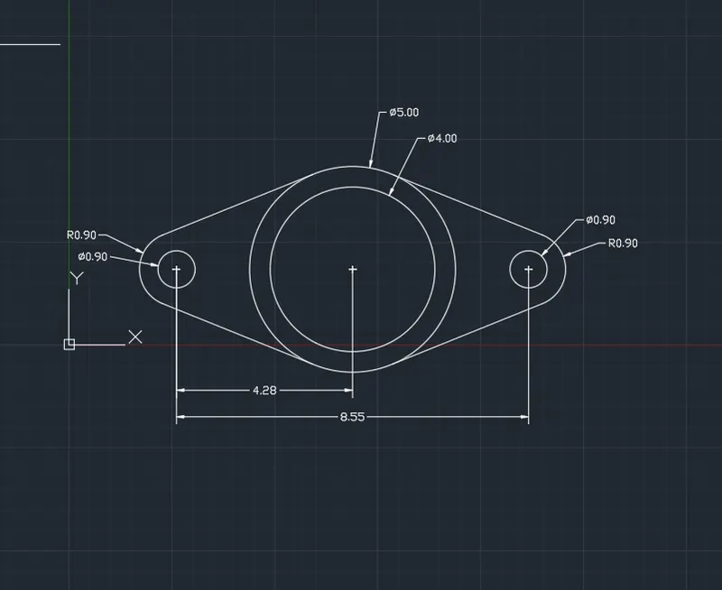
- Set Unit Desimal and set precision 0.00
- Take Line Command Specify first point (1,1)
- Go forward X direction 8.55 unit
- Draw two circle 0.9 unit of diameter and 0.90 unit of radius respectively from the both ending point of the line.
- Draw a circle of diameter of 4 unit and 5 unit respectively at the center point of the circle.
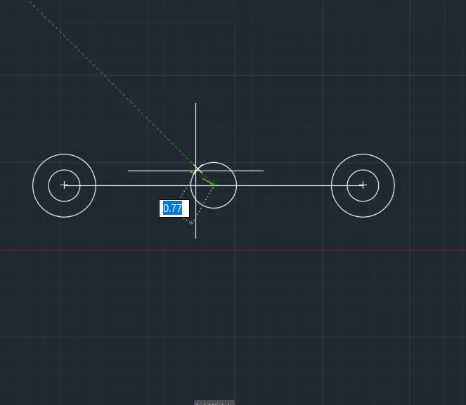
- on the grip snapping point and draw the tangent and draw tangent from center circle to both side of circle.uper and down both side.
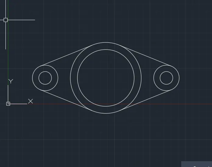
- With the help of trim or erase command trim the all unwanted lines .
- With the Help of Dimention command show all the dimention for angular dimension use DIMD for Diameter and DIMRA for radius measurement
DRAWING -9
TO DRAW THE FIGURE WE FILLOW THE FOLLOWING STEPS : -
Set all unit at Architectural format .
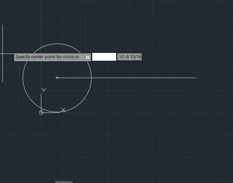
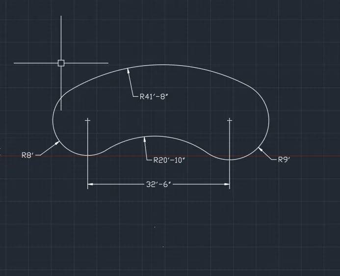
- Take line Command Speciy first point and make a line of 32'6" with x Direction.
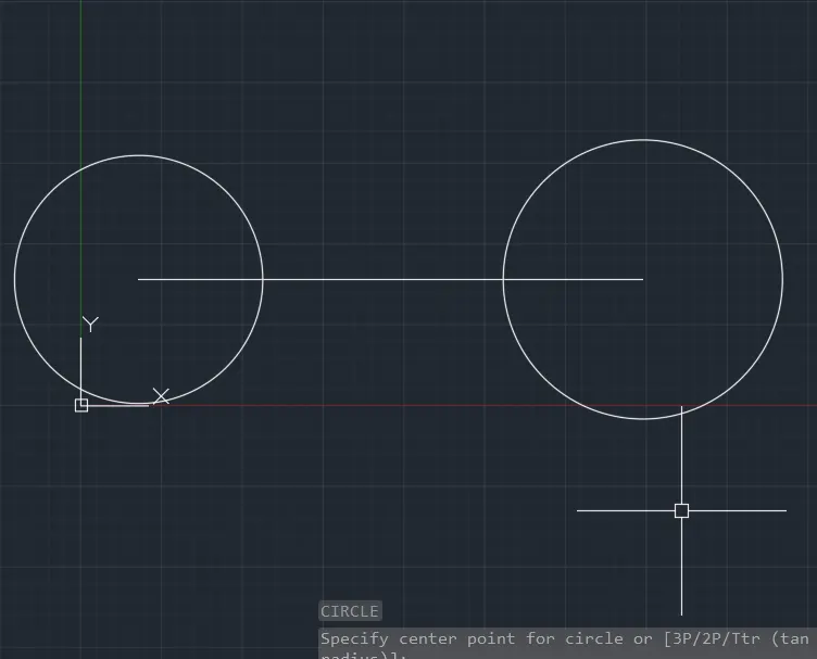
- Draw a Circle at first end point of line with 8' of radius.
- Draw a Circle last end point of line with 9' of radius.
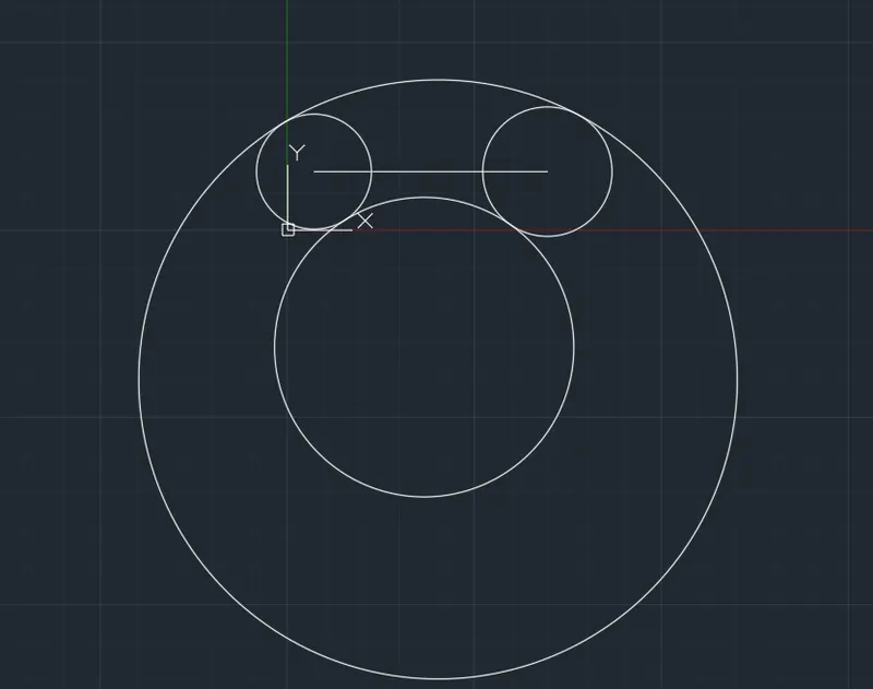
- Go to circle command and go with (Tan,tan ,radius ) of circle and draw a circle bottom side radius of 20'10"
- Again go with circle command and go with (Tan,tan ,radius ) of circle and draw a circle bottom side radius of 41'8" click tangent of circle upper side and draw a circle bottom side.
- With the help of trim or erase command trim the all unwanted lines .
- With the Help of Dimention command show all the dimention for angular dimension use DIMD for Diameter and DIMRA for radius measurement
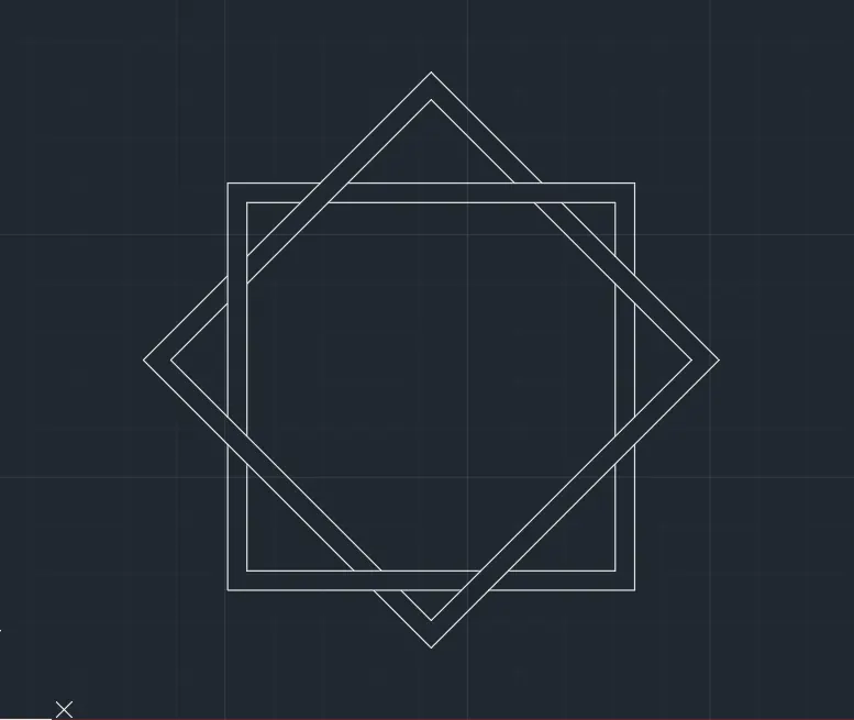
DRAWING -10
TO DRAW THE FIGURE WE FOLLOW THE FOLLOWING STEPS : -
Set all unit at Architectural format .
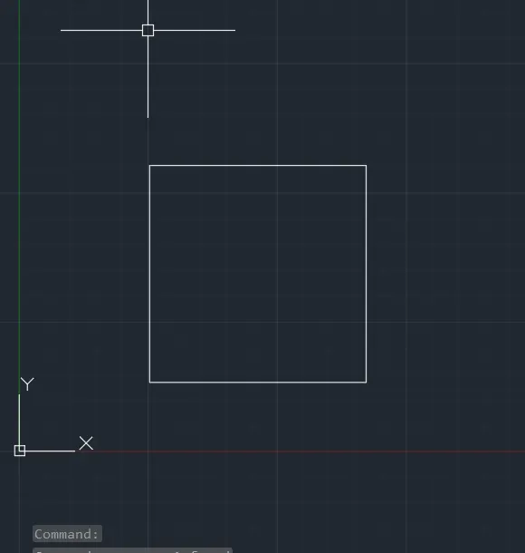
- Take rec. and specify first point , Draw a Square with 4 unit side.
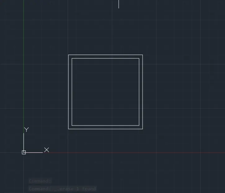
- Take offset command and take offset 0.2 unit in the internal side.
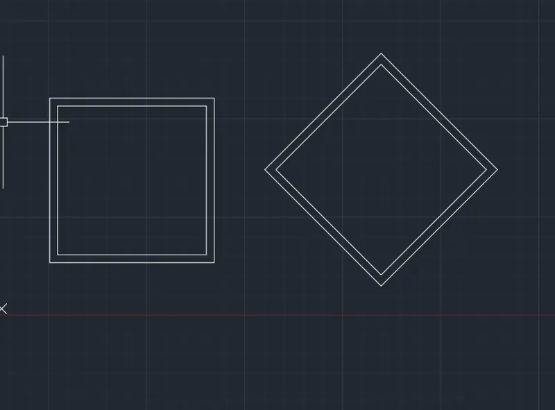
- Copy the object and Rotate this with angle of 45 degree.
picup the reteted figure and put the main object with the geometric center .
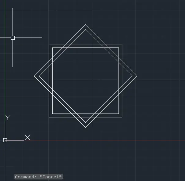
- With the help of trim or erase command trim the all unwanted lines .
- With the Help of Dimention command show all the dimention
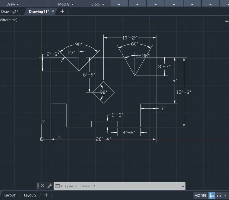
DRAWING -11
TO DRAW THE FIGURE WE FILLOW THE FOLLOWING STEPS : -
Set all unit at Architectural format .
- Set All the units Architectural Formats.
- Take A Line Command And specify first point (1,1)
- Draw Rectangle by line command with 20'4" lenght .
- Specify next point width 13'6" unit
- again take lenght 20'4"and width 13'6"
- take offset command and take offset 3' with last horizontal line.
- take agin offset 4'6" from last offset.
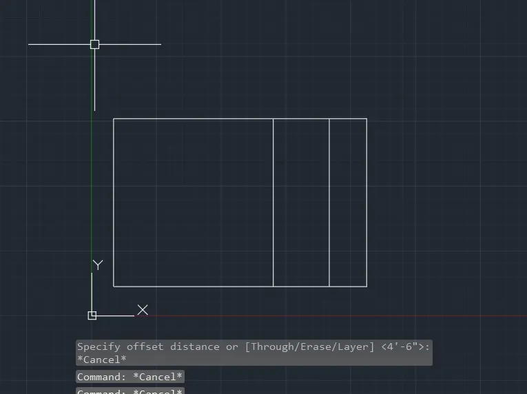
- Again take offset 2'8" from upper rec. line to down ward.
- again take offset 3' from first verticle line
- Draw verticle center line of the of the rectangle.
- Make a Squre 3'X3' and rotate this 45 degree.
- put 6'9" from the upper line.
- make the downward shape with the help of line command. used trim erase the umwanted line.
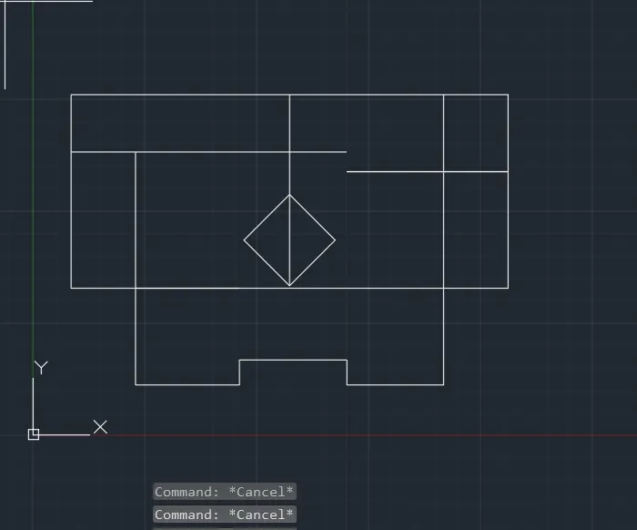
- Take perpendicular from down horzontal line and start an angle to intersecting point.
- Take 45 degree forward and 45 degree backward from the intersecting point.
- Take perpendicular from down 2nd horzontal line and start an angle to intersecting point. this angle star a offset 3'7" from vertical line.
- Take 30 degree forward and 30degree backward from the intersecting point.
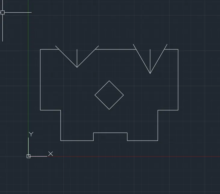
- With the help of trim or erase command trim the all unwanted lines .
- With the Help of Dimention command show all the dimention for angular dimension use DIMD for Diameter and DIMRA for radius measurement
RESULT:
All DRAWINGS ARE COMPLETE WITH THE HELP OF AUTOCAD COMMAND AND FINAL DRAWING IMAGES ARE BELOW SHOWN IN THE FIGURE : -
RESULT DRAWING -1
RESULT DRAWING -2
RESULT DRAWING -3
RESULT DRAWING -4
RESULT DRAWING -5
RESULT DRAWING -6
RESULT DRAWING -7
RESULT DRAWING -8
RESULT DRAWING -9
RESULT DRAWING -10
RESULT DRAWING -11