Creating Bar Bending schedule, Different Door types, and Creation of standard drawing templates using AutoCad
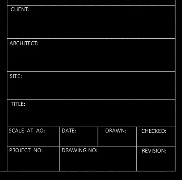
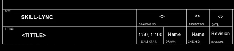
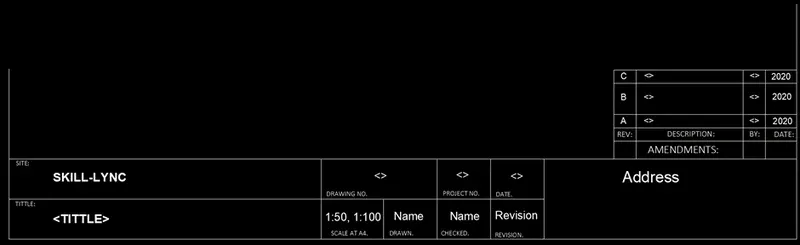
- Create the templates as shown in Figures. Take the size of the title block as per industry standards or
you can assume it as per the size of the paper. Use text and attributes wherever required. After creating
the title block you need to save it as a block with names: Custom1_titleblock and Custom2_titleblock,
respectively.
AIM:
To create the drawing template by using industry standards for size of the template by using the tools in the AutoCAD.
INTRODUCTION:
Drawing Template:
A drawing template file is drawing file that has been saved with a .dwt file extension, and it specifies the styles, settings and layouts in a drawing including tittle blocks.
PROCEDURE:
Template-1:
Step-1:
- For creating the template, we have to know the dimensions of the template.
- By using the template size as per the industry standards. Firstly, we have to draw the template table as per the dimensions.
- Select the command LINE to draw the outer line vertically and horizontally.
- Use the command OFFSET to draw the required parallel lines at specified distance.
- Use the command TRIM to eliminate the unwanted lines.

Step-2:
- After completing the outer and inner lines for the template now we have to write the text between them.
- Use the command DTEXT for labelling the text where ever the text is required.
- To specify the variations in text, we have to create new text styles for labelling.
Step-3:
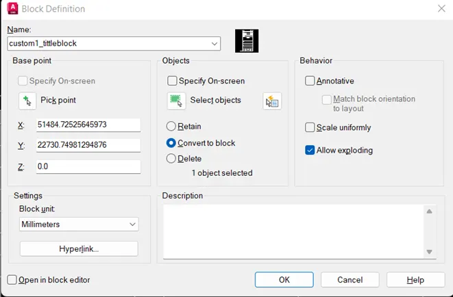
- After completing the template, now we have to create the template as block.
- The template is created as the block and save them in the system then we use the block in other drawing sheets also.
- Use the command BLOCK to create the template as block.
- Firstly, we select the object, and pick the base point and we have to give the name to the block.
Template-2:
Step-1:
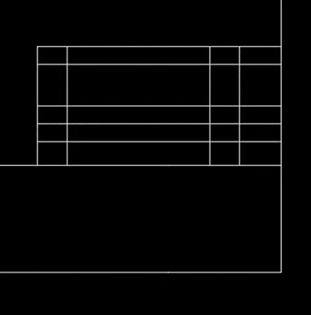
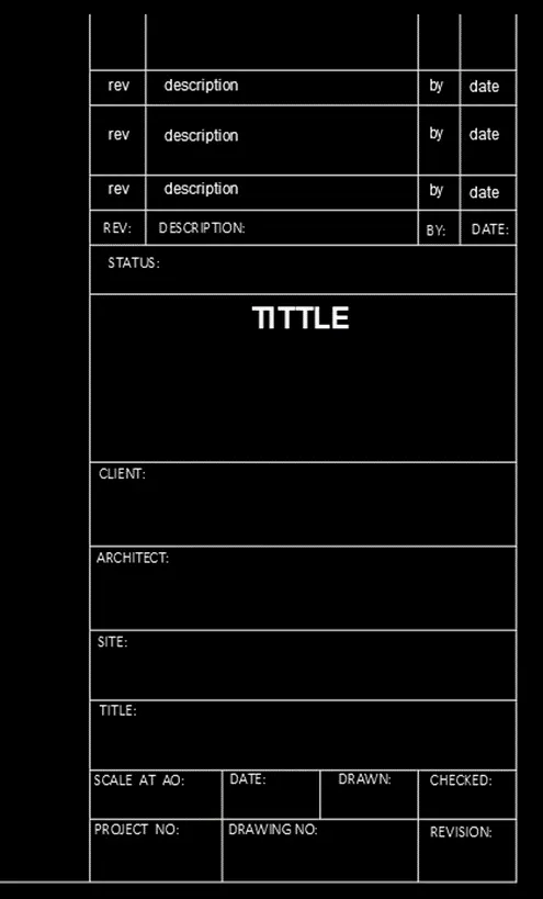
- For creating the template, we have to know the dimensions of the template.
- By using the template size as per the industry standards. Firstly, we have to draw the template table as per the dimensions.
- Select the command LINE to draw the outer line vertically and horizontally.
- Use the command OFFSET to draw the required parallel lines at specified distance.
- Use the command TRIM to eliminate the unwanted lines.
Step-2:
- After completing the outer and inner lines for the template now we have to write the text between them.
- Use the command DTEXT for labelling the text where ever the text is required.
- To specify the variations in text, we have to create new text styles for labelling.
Step-3:
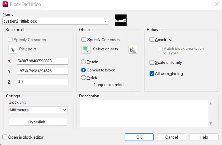
- After completing the template, now we have to create the template as block.
- The template is created as the block and save them in the system then we use the block in other drawing sheets also.
- Use the command BLOCK to create the template as block.
- Firstly, we select the object, and pick the base point and we have to give the name to the block.
RESULT:
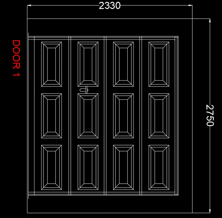
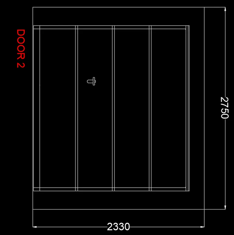
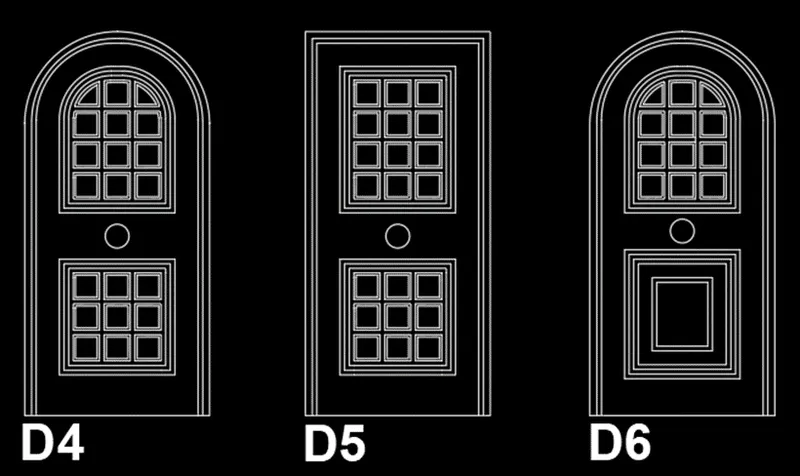
- Create the doors type for warehouse as shown in the Figure. You need to create each door type as per
standard size or given dimensions. Create the blocks of this door type after creating them.
AIM:
To create the door type for warehouse by using the standard dimensions by using the tools in AutoCAD.
INTRODUCTION:
A door is a movable barrier secured in an opening, known as the doorway through a building wall or partition for the purpose of providing access to the inside of a building or rooms of a building.
PROCEDURE:
Door-1:
Step-1:
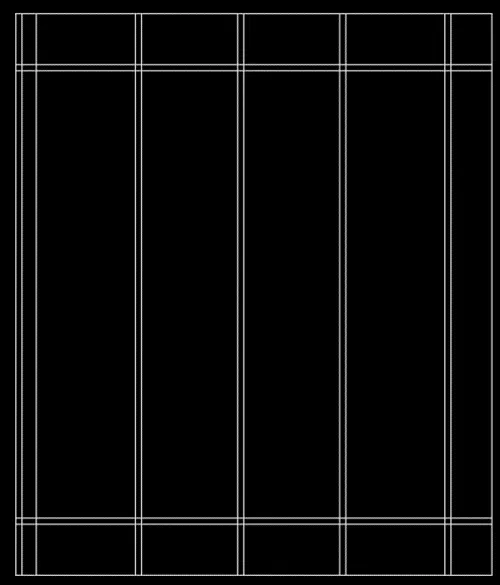
- For create a door we have to draw the outer lines for the sketch as per given dimensions, by using the command LINE draw the horizontal and vertical lines.
- Use the command OFFSET to draw the parallel lines and interior lines where ever they required.
- Use the command TRIM to eliminate the unwanted lines.
Step-2:
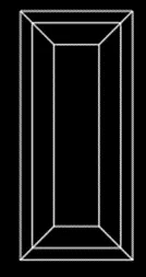
- After completing the outer and inner lines of the door, now we have to sketch the design on the door.
- Use the command LINE to draw the rectangle and use the command OFFSET to draw the internal rectangles as per the sizes.
- Use the command TRIM to eliminate the unwanted lines.
- After completing the sketch of the design, now we have to copy the sketch where ever it required.
- Use the command COPY and select the option multiple and pace the sketch where ever it required.
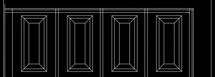
- Continue this process for entire door.
- After completing the sketch of door, we have to give the dimensions to the door by using the command DIMLIN.
- Use the command DTEXT for labelling the sketch.
Step-3:
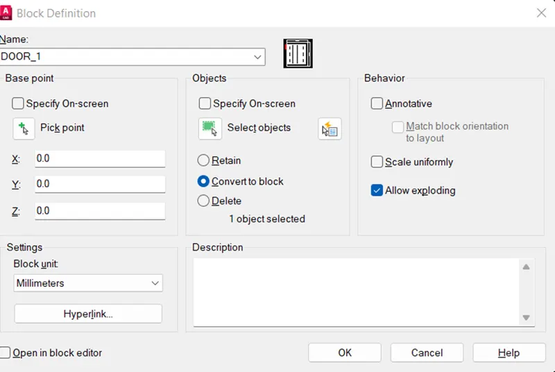
- After completing the door sketch, we have to save the door as the block and the saved block is used in other drawings also.
- Select the command BLOCK to create the door as block.
- Firstly, we select the object, and pick the base point and we have to give the name to the block.
Door-2:
Step-1:
- For create a door we have to draw the outer lines for the sketch as per given dimensions, by using the command LINE draw the horizontal and vertical lines.
- Use the command OFFSET to draw the parallel lines and interior lines where ever they required.
- Use the command TRIM to eliminate the unwanted lines.
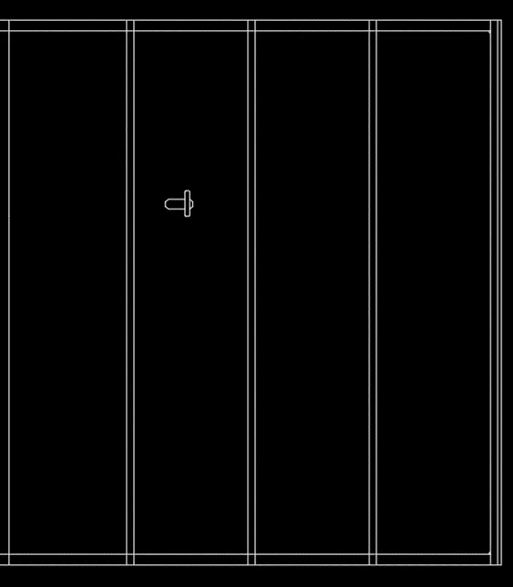
- After completing the sketch of door, we have to give the dimensions to the door by using the command DIMLIN.
- Use the command DTEXT for labelling the sketch.
Step-2:
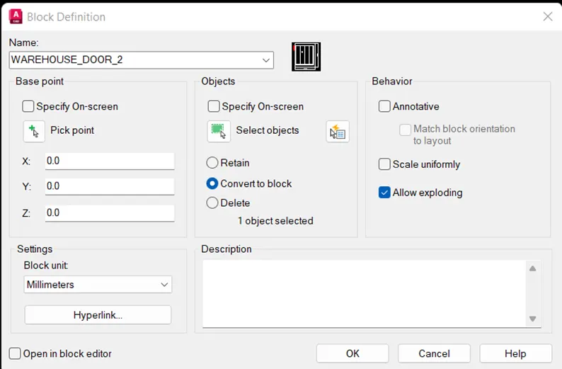
- After completing the door sketch, we have to save the door as the block and the saved block is used in other drawings also.
- Select the command BLOCK to create the door as block.
- Firstly, we select the object, and pick the base point and we have to give the name to the block.
RESULT:
- Create each symbol as a block with the name given in the legend. After creating the blocks arrange
them in the legend as shown in the Figure.
AIM:
To create the symbol legend and create them as blocks by using the tools in AutoCAD.
INTRODUCTION:
A symbol legend is the detailed explanation of contents on a map or drawing that uses symbols and short description of meaning.
PROCEDURE:
Step-1:
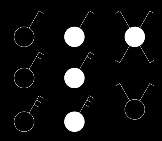
- For creating the symbol legend, we have to sketch the symbols.
- Select the command CIRCLE to draw the circles where ever they required.
- Use the command LINE to draw the lines and use the command OFFSET to draw the parallel lines.
- Use the command COPY to copy the sketch for other drawings and use the command MIRROR to sketch the lines.
- Select the command HATCH and use the pattern solid for highlighting the sketch.
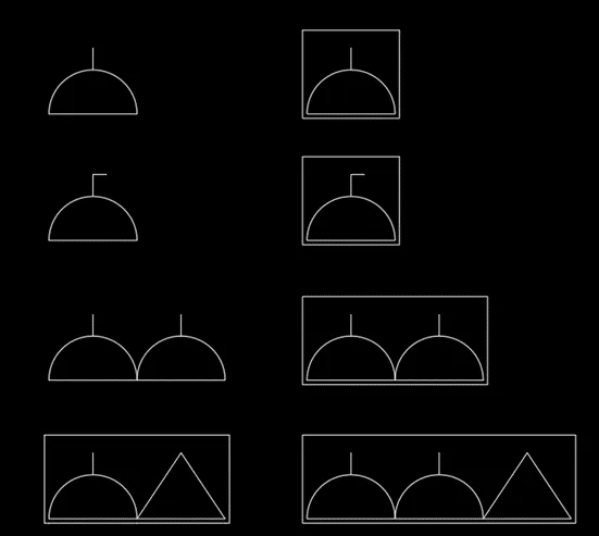
- Select the command LINE to draw the base line of the sketch.
- Then use the command ARC to draw the arc and use the command LINE to draw the vertical line.
- Use the command COPY for copy the sketch for other drawings.
- Use the command LINE to draw the square outside of the drawing.
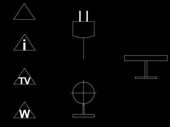
- Select the command LINE to draw the triangles and other sketches.
- Use the command COPY for copy the sketch for other drawings.
- Select the command CIRCLE to draw the circles where ever required.
- Use the command DTEXT to complete the labelling for the sketches.
Step-2:
- After completing the sketch of symbols, we have to save the symbols as the block and the saved block is used in other drawings also.
- Select the command BLOCK to create the symbol legends as block.
- Firstly, we select the object, and pick the base point and we have to give the name to the block.
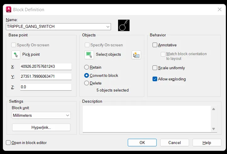
- Continue same procedure to create blocks for all symbols.
Step-3:
- After completion of creating the blocks for the symbols, we have to arrange them in a table.
- Select the command LINE to draw the border lines horizontally and vertically.
- Use the command OFFSET to draw the parallel lines and internal lines.
- By using the command INSERT to place the symbols in the table.
- The naming for the symbols given by using command
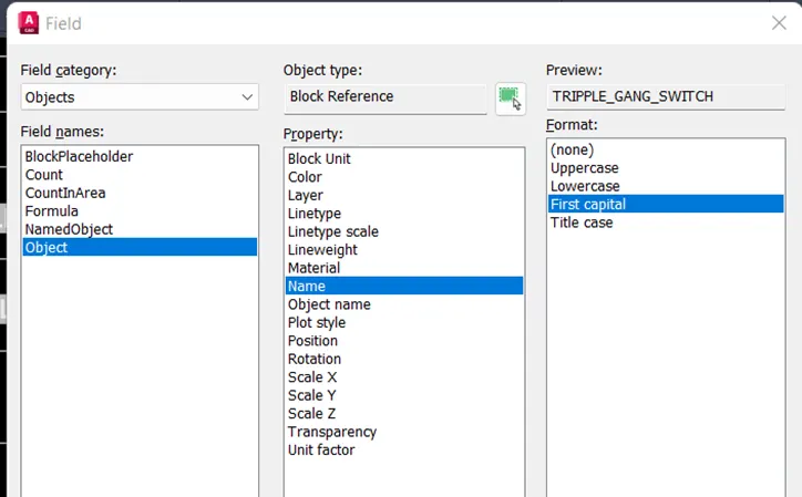
- Use the command DTEXT for labelling the sketch.
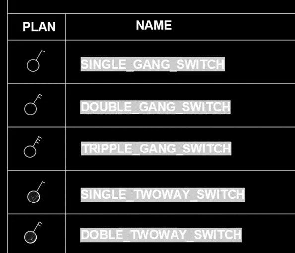
- Continue the same procedure for completing the arrangement of symbol legends in a table.
RESULT:
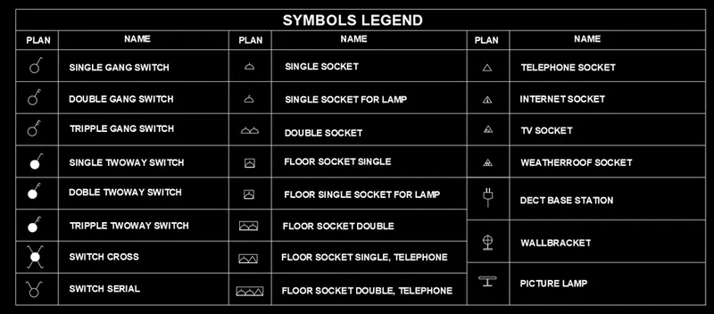
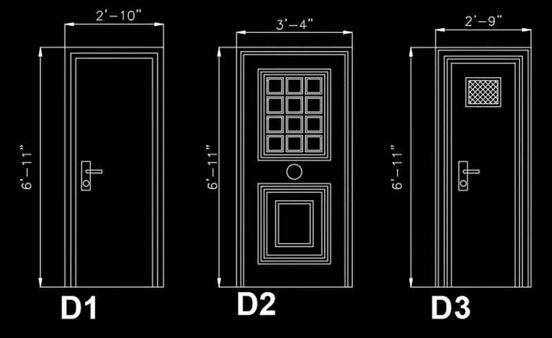
- Create the door type for residential building as a block. Save the name of the blocks as type. Use given
dimensions or assume dimensions as per industry standards.
AIM:
To create the door type for warehouse by using the standard dimensions by using the tools in AutoCAD.
INTRODUCTION:
A door is a movable barrier secured in an opening, known as the doorway through a building wall or partition for the purpose of providing access to the inside of a building or rooms of a building.
PROCEDURE:
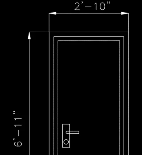
Door-1:
Step-1:
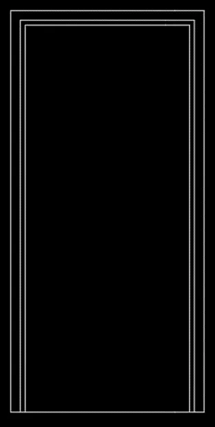
- For create a door we have to draw the outer lines for the sketch as per given dimensions, by using the command LINE draw the horizontal and vertical lines.
- Use the command OFFSET to draw the parallel lines and interior lines where ever they required.
- Use the command TRIM to eliminate the unwanted lines.
Step-2:
- After completing the door sketch, we have to draw the lock handle by using the command LINE.
- Select the command DIMLIN for complete dimensions of the sketch.
- Use the command DTEXT for complete the text.
Step-3:
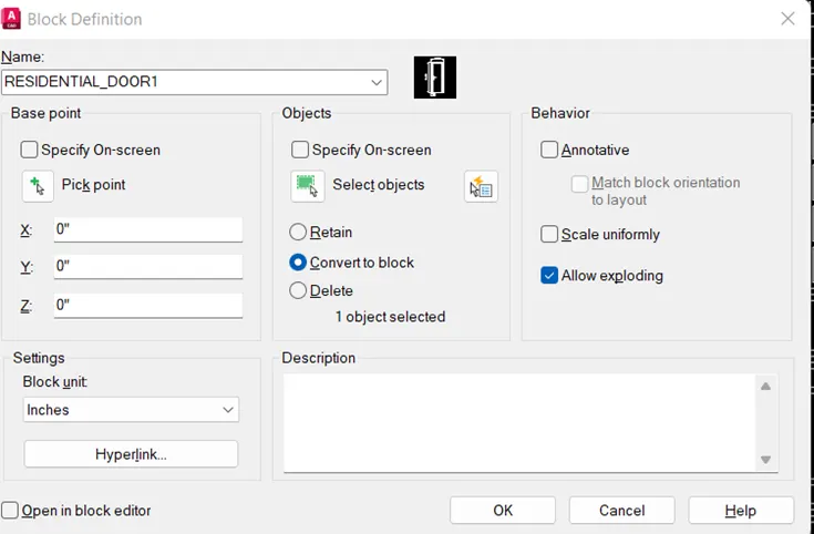
- After completing the door sketch, we have to save the door as the block and the saved block is used in other drawings also.
- Select the command BLOCK to create the door as block.
- Firstly, we select the object, and pick the base point and we have to give the name to the block.
Door-2:
Step-1:
- For create a door we have to draw the outer lines for the sketch as per given dimensions, by using the command LINE draw the horizontal and vertical lines.
- Use the command OFFSET to draw the parallel lines and interior lines where ever they required.
- Use the command TRIM to eliminate the unwanted lines.
Step-2:
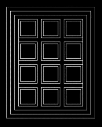
- After complete the outer sketch of the door, we have to create the design work on the door.
- Select the command LINE draw the out border horizontal and vertical lines.
- Use the command OFFSET to draw the parallel lines and interior lines where ever they required.
- Use the command TRIM to eliminate the unwanted lines.
- To sketch the squares between the lines we use the command LINE, command OFFSET and command CHAMFER.
Step-3:
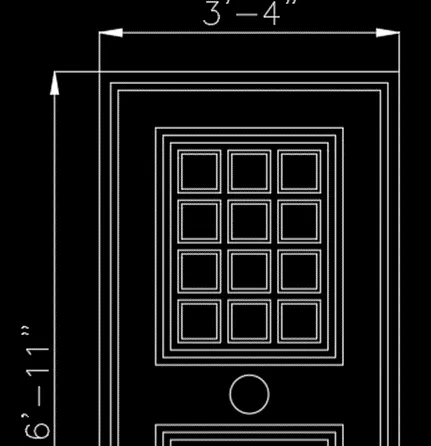
- After completing the design sketch, it should be placed on the door sketch, we have to draw the lock handle by using the command CIRCLE.
- Select the command DIMLIN for complete dimensions of the sketch.
- Use the command DTEXT for complete the text.
Step-4:
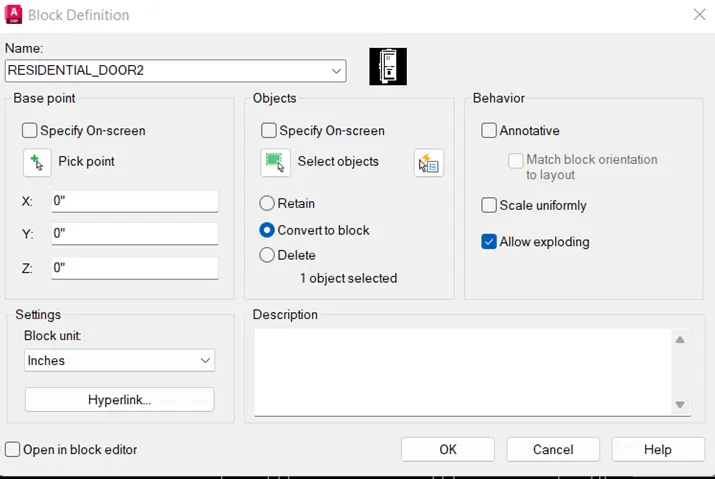
- After completing the door sketch, we have to save the door as the block and the saved block is used in other drawings also.
- Select the command BLOCK to create the door as block.
- Firstly, we select the object, and pick the base point and we have to give the name to the block.
Door-3:
Step-1:
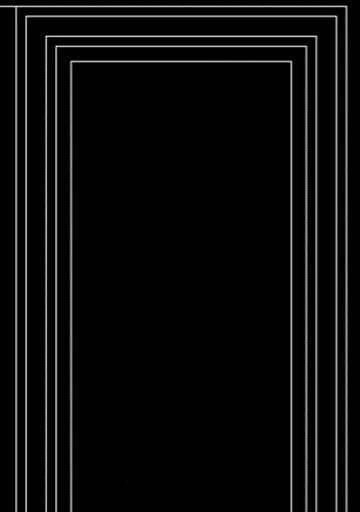
- For create a door we have to draw the outer lines for the sketch as per given dimensions, by using the command LINE draw the horizontal and vertical lines.
- Use the command OFFSET to draw the parallel lines and interior lines where ever they required.
- Use the command TRIM to eliminate the unwanted lines.
Step-2:
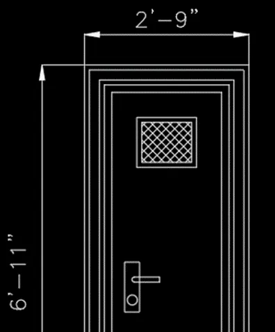
- After completing the door sketch, we have to draw the lock handle and small window on the door by using the command LINE.
- Use the command HATCH to highlighting the small window.
- Select the command DIMLIN for complete dimensions of the sketch.
- Use the command DTEXT for complete the text.
Step-3:
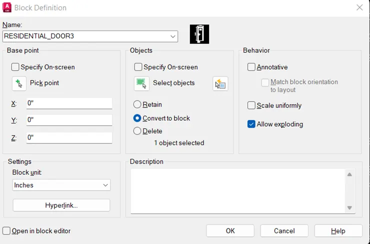
- After completing the door sketch, we have to save the door as the block and the saved block is used in other drawings also.
- Select the command BLOCK to create the door as block.
- Firstly, we select the object, and pick the base point and we have to give the name to the block.
- Follow the same process for completing the remaining doors.
RESULT:
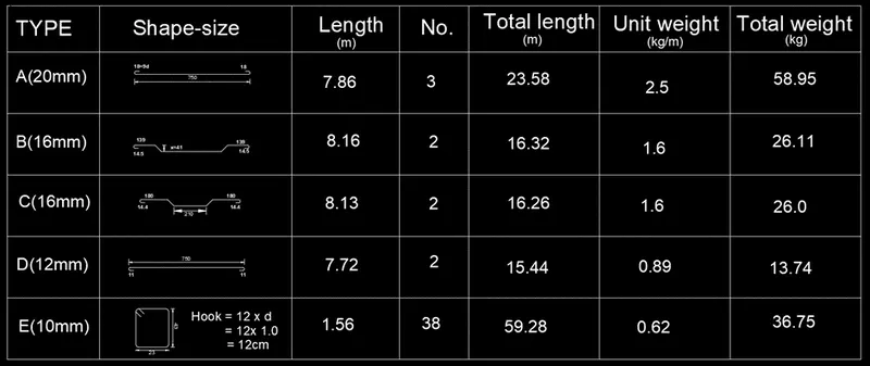
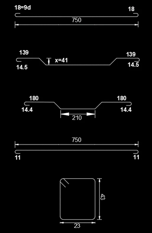
- Create each shape as a block as shown in the Figure. Save the block and insert them on the table as
shown in the Figure.
AIM:
To create the door type for warehouse by using the standard dimensions by using the tools in AutoCAD.
INTRODUCTION:
Bar bending schedule:
Bar bending schedule or schedule of bars (BBS) is a list of reinforcement bars for a given reinforced concrete work item and s presented in a tabular form for easy visual reference.
PROCEDURE:
Step-1:
- To sketch the bar bending schedule, first we have to draw the bars by using the command LINE.
- Use the command FILLET at the ends of every bar to show the curve.
- Use the command DTEXT for labelling the bars where the text is required.
- Use the command DIMLIN for completing the dimensions required at specified places.
Step-2:
- After completing the sketch of bars, we have to create the bars as blocks. The saved block is used in other drawings also.
- Select the command BLOCK to create the blocks for bars.
- Firstly, we select the object, and pick the base point and we have to give the name to the block.
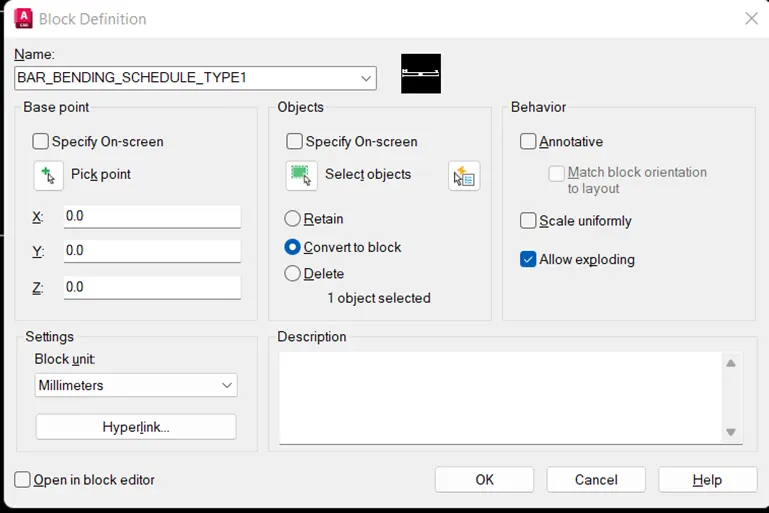
- Follow the same procedure to create the blocks for remaining blocks.
Step-3:
- After complete the creation of blocks for bars, we have to sketch the bar bending schedule.
- Select the command LINE to draw the outer border of the table.
- Use the command OFFSET to draw the parallel lines and inner lines.
- Use the command INSERT to place the bars in the table.
- Se the command DTEXT to specify the text where it required in the table.
- To specify the variations in text, we have to create new text styles for labelling.
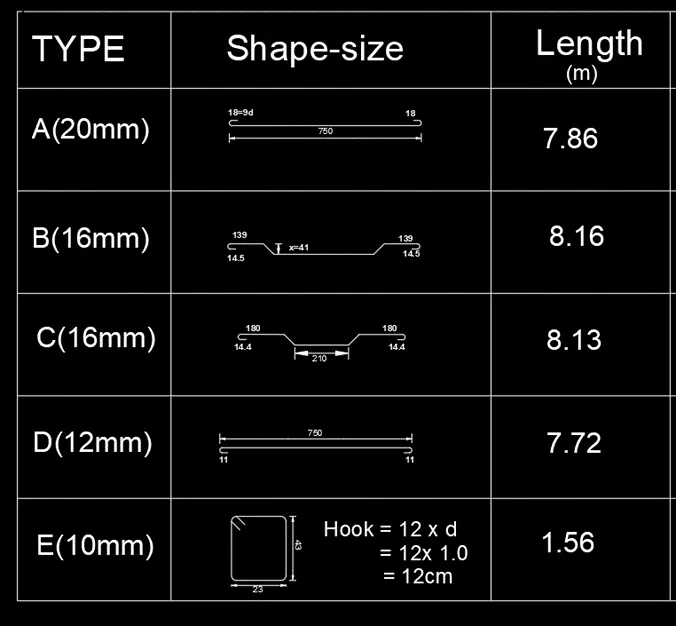
- Follow the same procedure to complete the bar bending schedule.
RESULT: