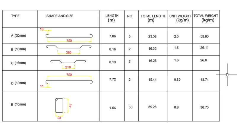
Creating Bar Bending schedule, Different Door types, and Creation of standard drawing templates using AutoCad
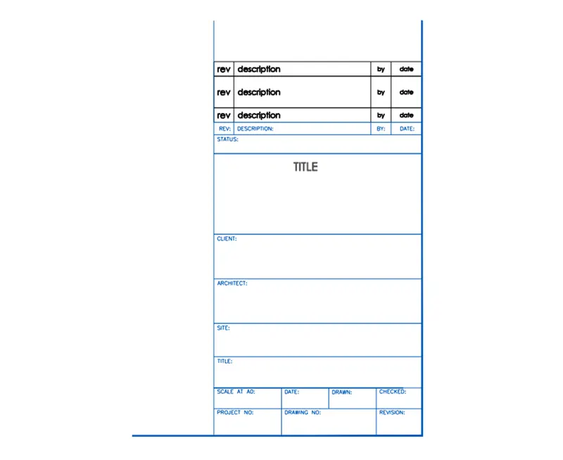
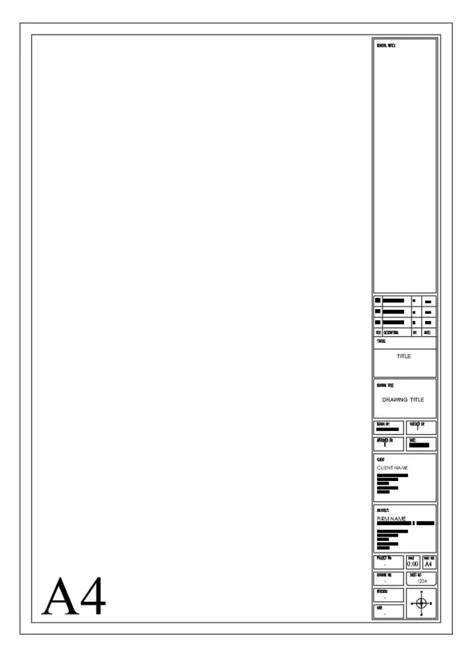
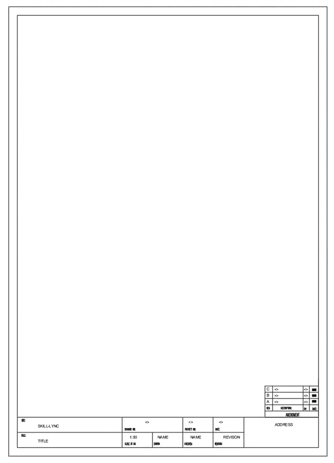
Q: 1. Create the templates as shown in Figures. Take the size of the title block as per industry standards or you can assume it as per the size of the paper. Use text and attributes wherever required. After creating the title block you need to save it as a block with names: Custom1_titleblock and Custom2_titleblock, respectively.
AIM:
To Create the templates by Taking the size of the title block as per industry standards or we can assume it as per the size of the paper and Using text and attributes wherever required.
After creating the title block, we need to save it as a block with names: Custom1_titleblock and Custom2_titleblock, respectively.
INTRODUCTION:
Templates in AutoCAD is a baseline for your work. It helps you to easily create a future drawing without initial settings. Using templates reduces work time, reduces the chance to make mistakes in settings and makes uniformity to every work in a single project.
PROCEDURE:
- Open the cad software and then set up the units by using UN command
- Set the limits by using LIM command
- Now the A4 size is 210x297 create the rectangle with these sizes.
- By using offset and rectangle command create the templates.
- Click Home tab Block panel Define Attributes.
- In the Attribute Definition dialog box, set the attribute modes and enter tag information, location, and text options. Click OK.
- Create or redefine a block (BLOCK).
- Now create the block and select the object which we create the and save as
- And again, create block 2nd template file and define it and save it as
Templet file 1
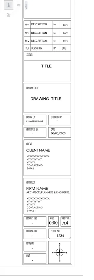
Templet file2
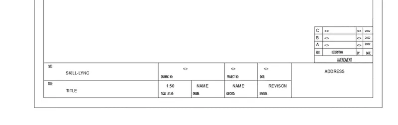
RESULT:
The templet files is successfully created by using AutoCAD software. And it defined block which save as Custom1_titleblock and Custom2_titleblock.
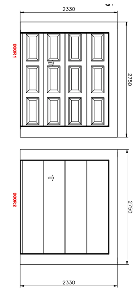
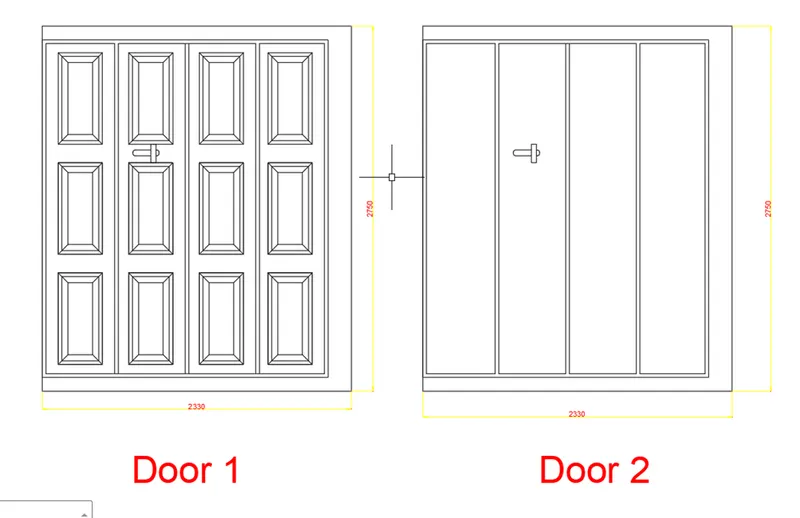
Q2. Create the doors type for warehouse as shown in the Figure. You need to create each door type as per standard size or given dimensions. Create the blocks of this door type after creating them
AIM:
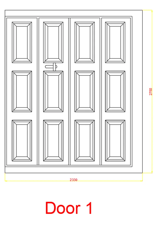
To Create the doors, type for warehouse and we need to create each door type as per standard size or given dimensions and also Create the blocks of this door type after creating them.
INTRODUCTION:
A door is a hinged or otherwise movable barrier that allows ingress (entry) into and egress (exit) from an enclosure. The created opening in the wall is a doorway or portal. A door's essential and primary purpose is to provide security by controlling access to the doorway (portal).
PROCEDURE:
- Select a door tool on a tool palette.
- Alternatively, we can click home tab Build panel Door drop-down
- In the drawing, select a wall or a door and window assembly in which to insert the door, or press Enter to add a freestanding door.
- Specify the insertion point for the door.
- To have full flexibility for defining the insertion point, verify the following:
- The Position along wall setting on the Properties palette is set to Unconstrained.
- The OSNAP setting in the status bar is turned off.
- Otherwise, the door insertion point will be aligned to the centre or end points of the wall, or to any of the active OSNAP points.
- Enter cy(cycle measure to) once or twice on the command line in order to switch the insertion point of the door from hinge (default) to centre and latch.
- Enter re(Reference point on) in order to measure the insertion, point of a door in relation to a specified point in the drawing.
- Select the justification.
- Continue adding doors, and press Enter.
- Define block and create the block which we created.
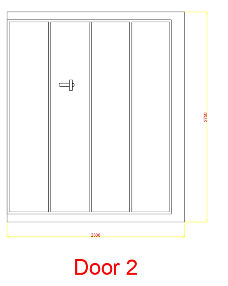
RESULT:
The doors, type for warehouse is successfully created by using AutoCAD software and we created each door type as per standard size or given dimensions and also Created the blocks of this door type.
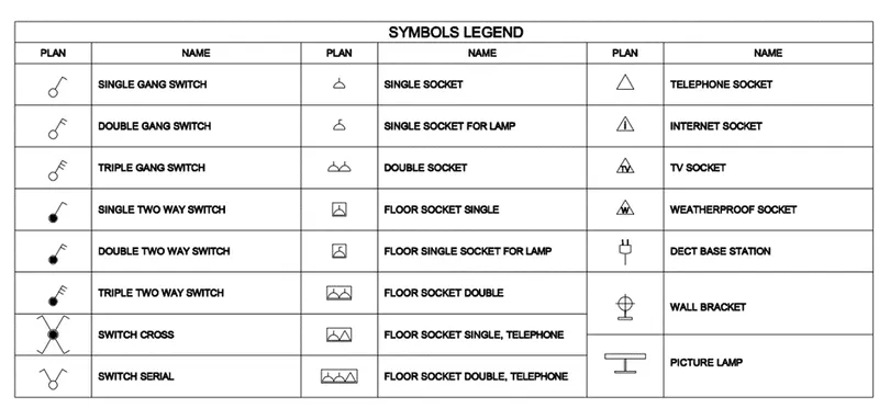
Q3. Create each symbol as a block with the name given in the legend. After creating the blocks arrange them in the legend as shown in the Figure.
AIM:
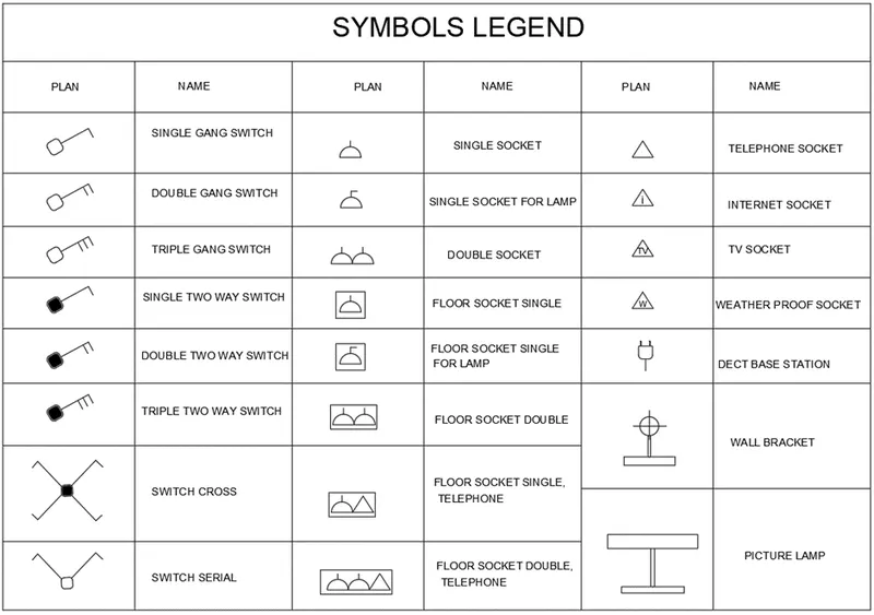
To Create each symbol as a block with the name given in the legend. After creating the blocks arrange them in the legend.
INTRODUCTION:
A Symbol and Legend is the detailed explanation of contents on a map or drawing that uses symbols (simplified shape) and short descriptions of meaning.
PROCEDURE:
- By using line command and arc command draw the line and create arc.
- Then create object define block and name it as ‘single gang swich’.
- After that create another object by copying previous object and do modification.
- Define block and select the object and give the pickup point and name it as double gang swich.
- Do the similar procedure to the all objects and create the blocks.
- After that create a table by using line command then insert the block by using I command
- Name it by using DT command
- After that save it.
RESULT:
The legend symbol is created successfully by using AutoCAD software and each symbol defined as a block with the name given in the legend and also creating the table format and arrange them in the legend.
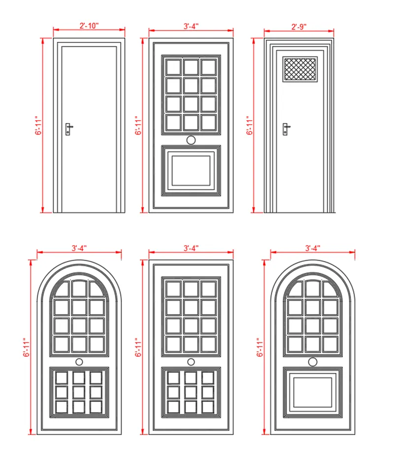
Q4. Create the door type for residential building as a block. Save the name of the blocks as type. Use given dimensions or assume dimensions as per industry standards
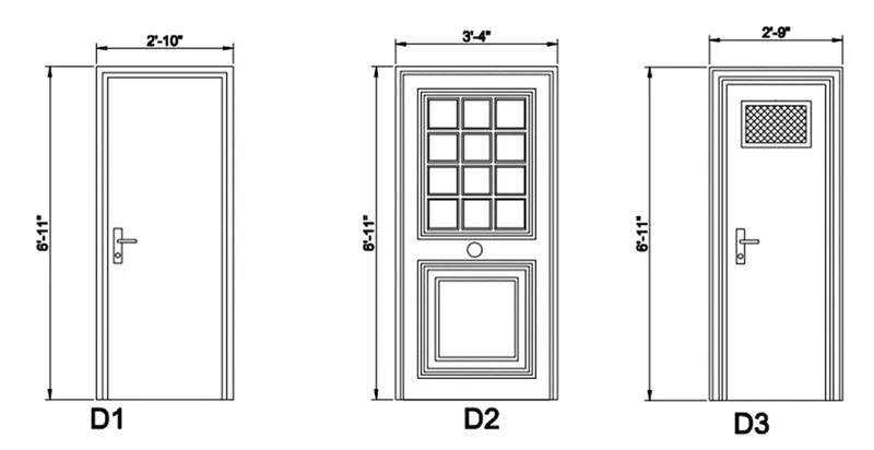
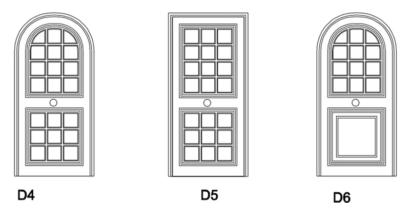
AIM:
To Create the door type for residential building as a block and save the name of the blocks as type. Use given dimensions or assuming dimensions as per industry standards
INTRODUCTION:
A door is a hinged or otherwise movable barrier that allows ingress (entry) into and egress (exit) from an enclosure. The created opening in the wall is a doorway or portal. A door's essential and primary purpose is to provide security by controlling access to the doorway (portal).
PROCEDURE:
- Select a door tool on a tool palette.
- Alternatively, we can click home tab Build panel Door drop-down
- In the drawing, select a wall or a door and window assembly in which to insert the door, or press Enter to add a freestanding door.
- Specify the insertion point for the door.
- To have full flexibility for defining the insertion point, verify the following:
- The Position along wall setting on the Properties palette is set to Unconstrained.
- The OSNAP setting in the status bar is turned off.
- Otherwise, the door insertion point will be aligned to the centre or end points of the wall, or to any of the active OSNAP points.
- Enter cy(cycle measure to) once or twice on the command line in order to switch the insertion point of the door from hinge (default) to centre and latch.
- Enter re(Reference point on) in order to measure the insertion, point of a door in relation to a specified point in the drawing.
- Select the justification.
- Continue adding doors, and press Enter.
- Define block and create the block which we created.
RESULT:
The door type for residential building is created successfully in AutoCAD software and defined as a block and saved the name of the blocks as type Using given dimensions or assuming dimensions as per industry standards.
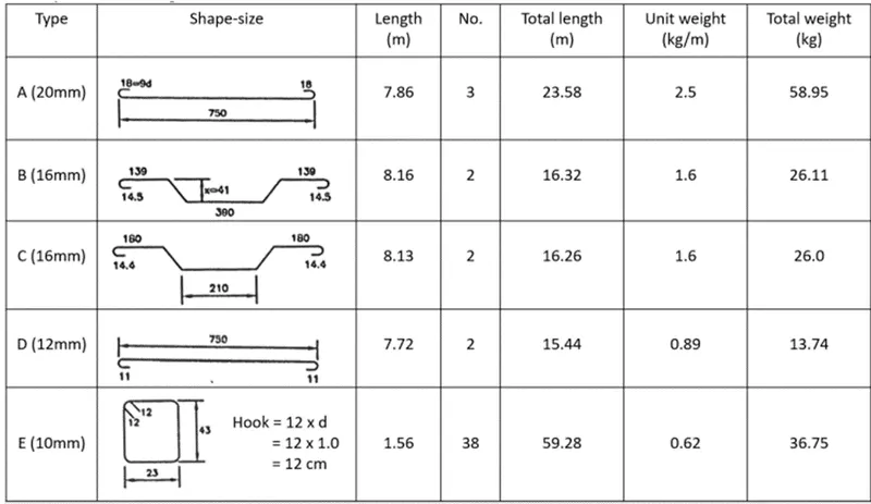
Q5. Create each shape as a block as shown in the Figure. Save the block and insert them on the table as shown in the Figure.
AIM:
To Create each shape as a block as shown in the Figure and Save the block and insert them on the table
INTRODUCTION:
Bar Bending Schedule helps to determine the quantity of steel required in construction of your house. This helps to get the accurate estimation of steel. Once the calculation of cutting and bending is done it reduces the wastage of steel and it becomes economic.
PROCEDURE:
- In the command prompt type Unit>decimal>meters
- In the command prompt type limits >0,0
- In the command prompt type LIMAX >100,100
- In the command prompt type I to draw the desired lines
- In the command prompt type pl to draw the desired arc, poly lines
- In the command prompt type MT to give annotation and text
- In the command prompt type B to create the block
- In the command prompt type I to insert the created in the block
- In the command prompt type table to inset the table
- In the command prompt type DT create text in the table.
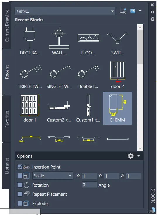
RESULT:
The bar bending schedule is successfully Created by using autocad software and defined each shape as a block as shown in the Figure and Saved the block and inserted them on the table