Creating Bar Bending schedule, Different Door types, and Creation of standard drawing templates using AutoCad
DIAGRAM 1.
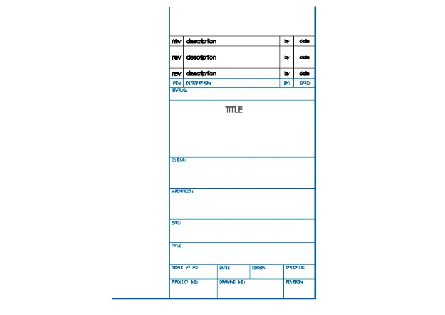
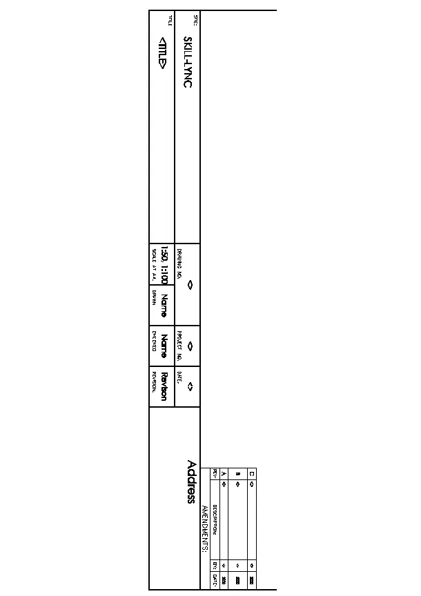
AIM : Create the templates as shown in Figures.
INTRODUCTION :
The Title block of a drawing, usually located on the bottom or lower right hand corner, contain all the information necessary to identify drawing and to verify its validity.
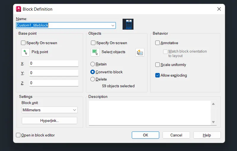
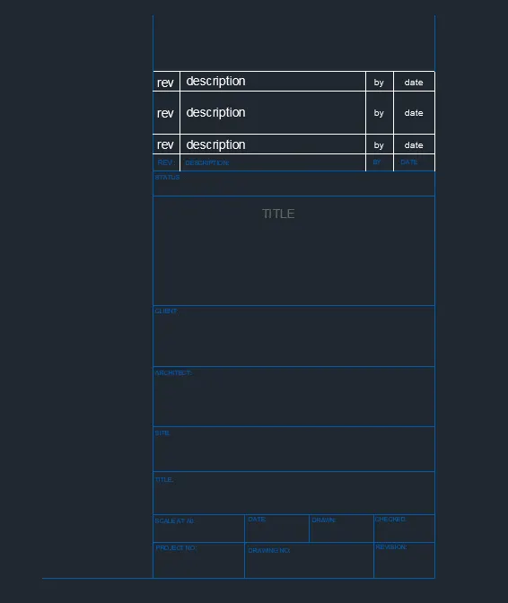
we have Taken the size of the title block as per industry standards and we have assumed it as per the size of the paper. we have Used text and attributes wherever required. After created the title block we have saved it as a block with names: Custom1_titleblock and Custom2_titleblock, respectively.
PROCEDURE :
1. TITLE BLOCK .
step-1
- type un for unit command
- set unit to decimal milimeter
- type line command
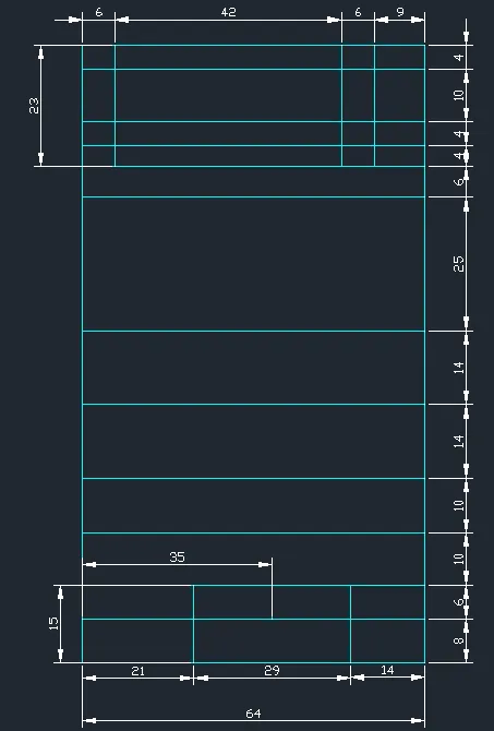
- make horizontal line distance of 64mm
- type o for offset command
- make offset of 8mm above the horizontal
- after that make offfset of 6,10,10, 14,14,25,6,4,4,10,4mm in continuous manner
- now make horizontal line
- type line command
- join the vertical lines to corner point of top and bottom line at both sides line
- type offset command give offset of 6, 42,6 and 9 from same vertical line
- vertical height of line such a that it connect from top to 5th line from top line at left side
- type offset command give offset of 21, 29 and 14 from same vertical line at left side
- vertical height of line such a that it connect from bottom line to 3rd line from bottom line
step-2
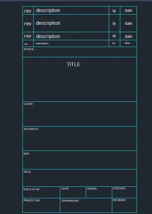
- type st for text style set height of text
- make custom style
- type attdef for attributes
- fill the box tag, prompt, default
- and fill the table by text
- in above first 3 rows the text are same use copy and array option
- change the height of text
- use attribute command
- write other texts in box
step-3
- go to layer properties make new layer and set colours
- using layer convert lines into layer
- type B for block definition
- give title custom1_titleblock
- select object
- select pick point and then ok.
Step-4 :
- keep the same unit as above
- type line command
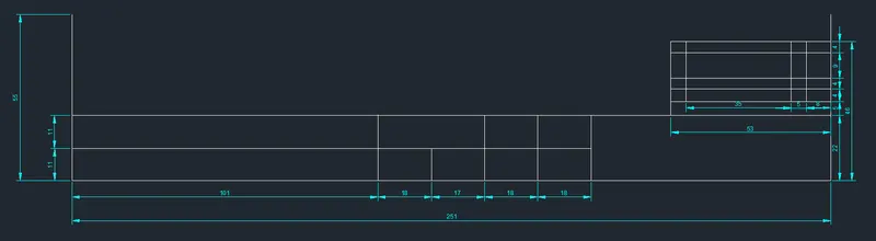
- make horizontal line distance of 251mm
- type o for offset command
- make offset of 11mm above the horizontal
- after that make offfset of11,5,4, 4,9,4mm in continuous manner
- now make vertical lines
- type line command
- join the vertical lines to corner point of top and bottom line at right side
- type offset command give offset of 6, 42,6 and 9 from same vertical line
- vertical height of line such a that it connect from top to bottom line at left side
- at right side cornermake line of distance 55 vertical
- type offset command give offset of 8, 5,5, 35 from same vertical line at left side
- type offset command give offset of 101, 18,17, 18, 18 from same vertical line at right side
- type trim command using trim erase unwanted line and make a table as shon in below fig.
step-5 :
- type st for text style set height of text
- make custom style
- type attdef for attributes
- fill the box tag, prompt, default
- and fill the table by text
- change the height of text
- use attribute command
- write remaining other texts in box
- go to layer properties make new layer and set colours
- using layer convert lines into layer
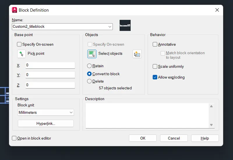
- type B for block definition
- give title custom2_titleblock
- select object
- select pick point and then ok.
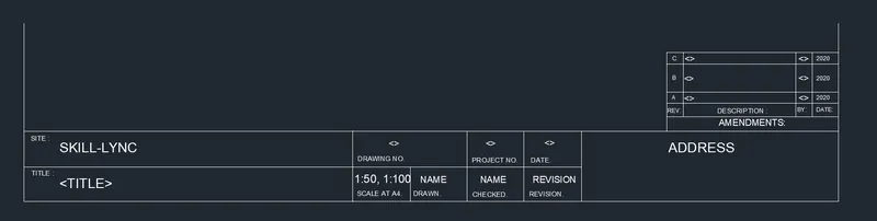
RESULT :
we have created Custom1_titleblock and Custom2_titleblock, respectively.
2.DIAGRAM
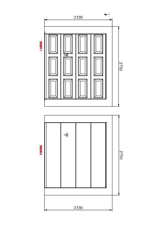
AIM : Create the doors type for warehouse as shown in the Figure.
INTRODUCTION :
we have created each door type as per given dimensions. we have Created the blocks of this door type after creating them.
PROCEDURE :
step-1 :
- type un for unit
- select decimal milimeter
- type rec for rectangle
- give the dimensions, specify first corner point
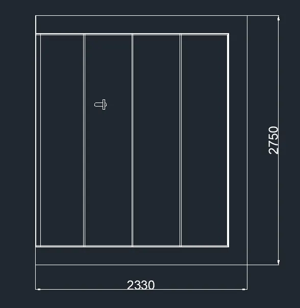
- give the length 2330 and width 2750
- type explode and explode the triangle
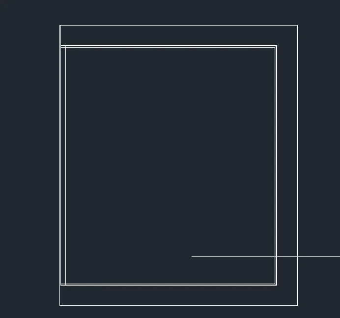
- type offset and give offset to three sides of rectangle inside
- give offset of 200 to all three sides
- no offset for left vertical line
- type f and fillet the corner or use trim command
- make such other offset as shown in fig
step-2 :
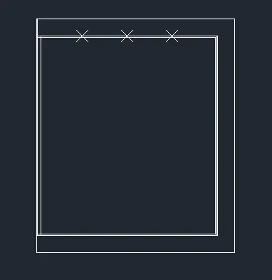
- type ddptype and select point style
- type divide and divide the line of second line from above line in 4 segments
- keep ortho mode on
- join this point by vertical line to second last line from bottom
- now offset this this 3 vertical line
- give offset of 8 at each left and right side
- and erase the middle vertical line
- erase the point style
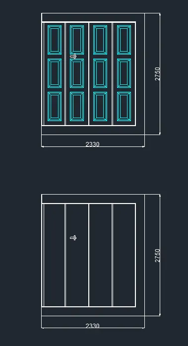
- make offset of 90, 70 and 85 from left, top and right side as shown in fig. in cyan colour
- type rec and make rectangle having dimensions 300 x 640
- erase the other lines
- now make 3 offset for this rectangle
- offaet must be inside the rectangle
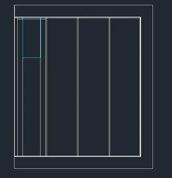
step-3 :
- type array, slect rectangular array
- slect the column > enter the number of column > specify spacing for column
- select the row > enter number of row> speicfy row distance
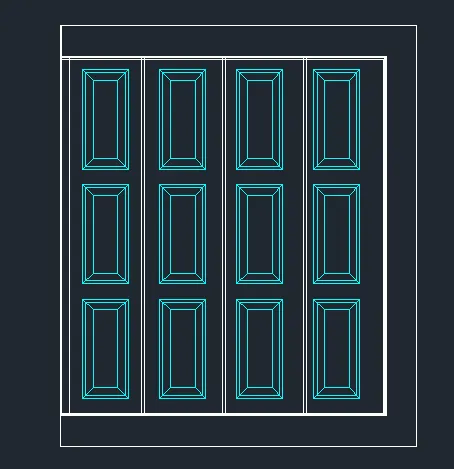
step-4 :
- convert this array block into layer
- type l for line command and make following fig using suitable dimensions
- by keeping ortho mode on/off
- 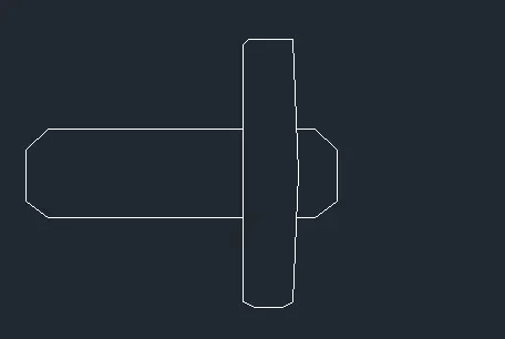
- paste this fig in main drawing
- type dimlin and give the dimension to rectangle
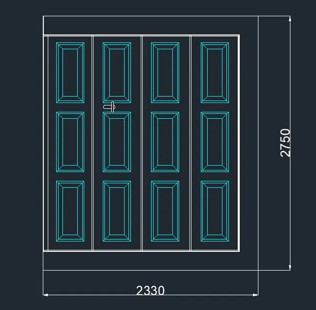
step-5 :
- turn off the array panel layer
- copy the above figure
- type copy > select object > give the location
STEP-6 :
- convert it into block
- type b for block
- give title> select object > pick point . ok
RESULT :
we have Created the doors type for warehouse as shown in the Figure.
3.DIAGRAM
AIM:
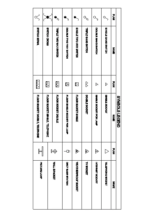
Create each symbol as a block with the name given in the legend. After creating the blocks arrange them in the legend as shown in the Figure.
INTRODUCTION :
Create a legend that lists the layers in your map, using a color key that identifies each one. The legend is an object that you drop into place on your paper space layout.we have created legends using various command and arrange them as shown in figure.
PROCEDURE :
step-1 :
- Type un for unit > select decimal milimeter
- type c for circle > specify centre point > give radius 25
- type l form line make inclined line taking random point.

- copy the above object
- type l for line and make line parellal to above inclined line at distance 0f 15

- copy the above object
- type l for line and make line parellal to above inclined line at distance 0f 15

- copy the first object
- type offset and give inside offset to circle
- select hatch > give solid hatch to inner circle

- copy the above object
- type l for line and make line parellal to above inclined line at distance 0f 15

- copy the above object
- type l for line and make line parellal to above inclined line at distance 0f 15

- copy the above object
- type trim and erase 2 short lines which is parellal
- use mirror command to mirror the line section

- copy the above object
- trim the bottom lines of the circles

- type line command make horizontal line
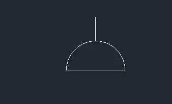
- make semicircle using circle and then trim command
- make top line using line command
- copy the above object
- type line command
- make horizontal line to top corner of top line at rght side
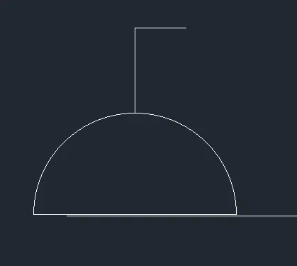
- copy the above object
- use mirror command and mirror the object
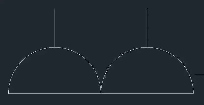
- copy the above object
- type rec command and make rec outside the object
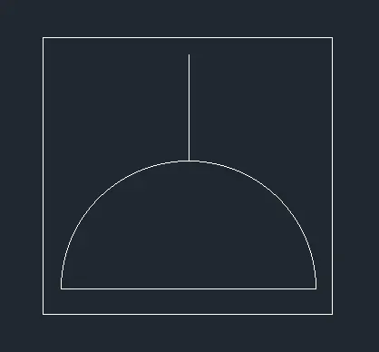
- copy the above object
- make horizontal line to top corner of top line at rght side
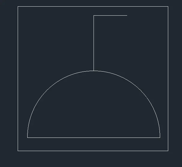
- copy the object
- type rec for rectangle and make rectangle out of it
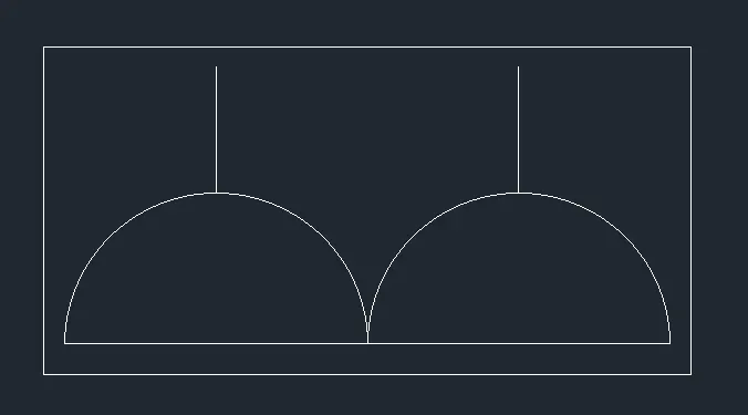
- copy the above object
- erase the mirror object
- type line command and make triangle
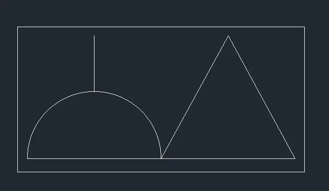
- copy the object which has 2 semicircle digram
- type l for line and make triangle attach tomit
- type rec and make rectangle out side the digram
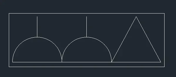
- type line command and make triangle out of it

- copy the above object
- type attdef for attribute type text inside the triangle
- copy the traingle object
- make other fig



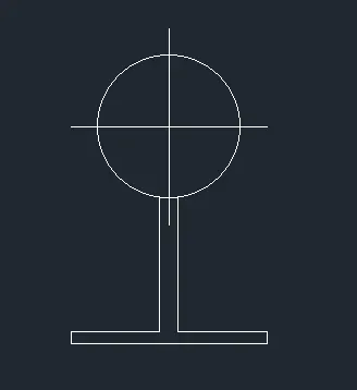
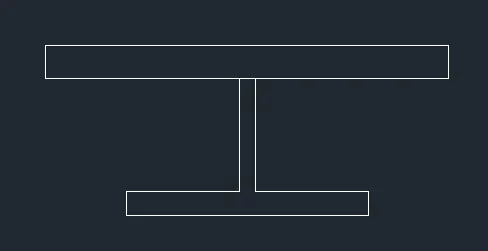
- using line, circle, command make following fig
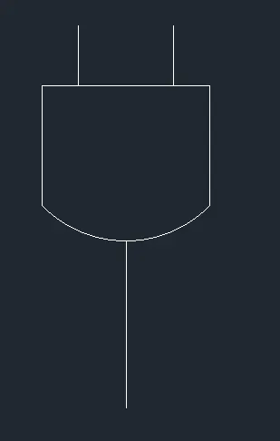
step-2 :
- type b for block and make block of above fig seperatly
- give the title to block > select object > pick point > ok
- do this for every figure
step-3 :
- type table command and make table having 6 columns and 8 rows
- adjust the column spacing of table
- using scale command adjust the table size as per blocks made
step-4 :
- type insert for inserting blocks insert the all blocks
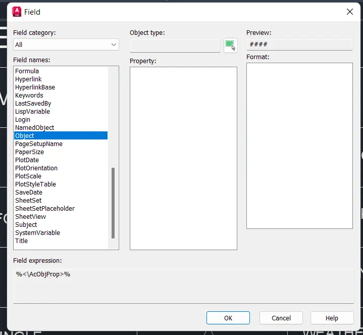
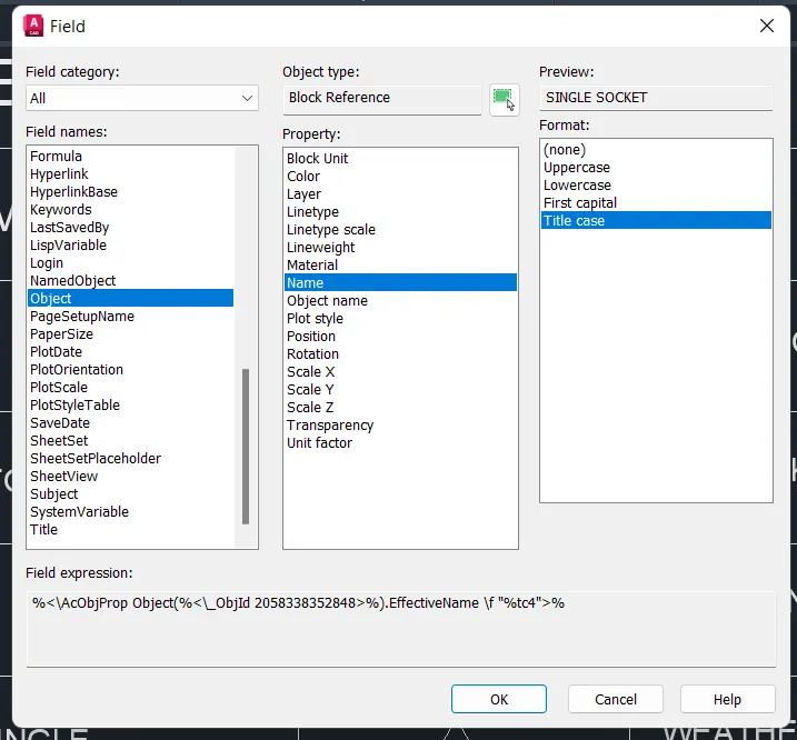
- go to insert on ribbon > select field > go to object > select symbol of slecting object > select object > select name
- paste this name in table maintain the height of text
- type explode and explode the text so that background colour will remove
- do this process for all blocks
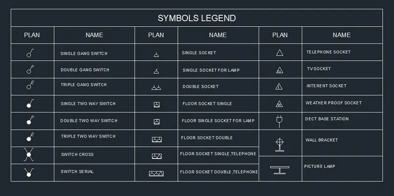
RESULT :
We have Created each symbol as a block with the name given in the legend
4. DIAGRAM
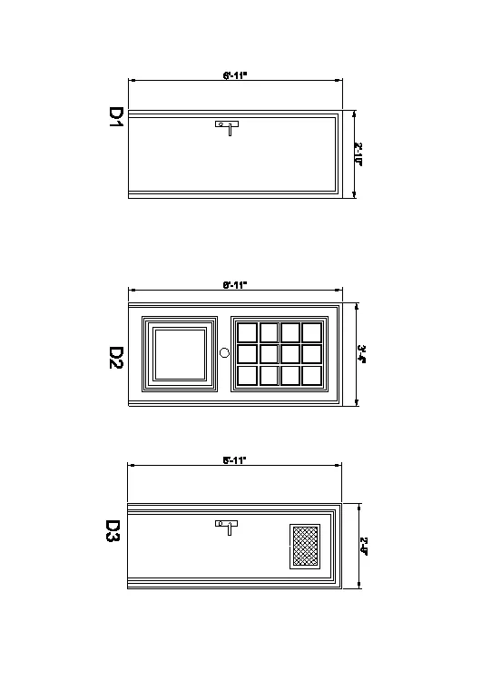
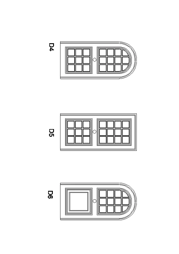
AIM : Create the door type for residential building as a block.
INTRODUCTION :
Save the name of the blocks as type. Use given dimensions or assume dimensions as per industry standards.
PROCEDURE :
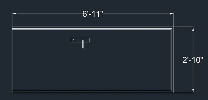
D1.
step-1
- type un for unit
- set unit to engineering > inches
- type rec command for rectangle
- give dimensions 6'10" x 2'10"
- type o for offset give offset of 1" inside the rectangle
- type o for offset give offset of 0.5" inside the rectangle
- type trim > trim the lines which is at left side just leave the outer rec line
- type ex for extend command and extend all the cuting lines
- type rec command make locker of door
- use circle command to draw circle
- type dimlin for dimensions and give dimenstions
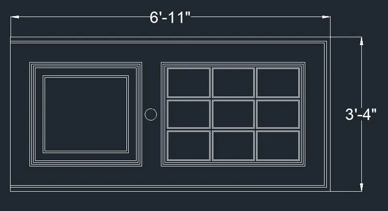
D2.
step-2 :
- type rec and give dimensions 6'10" x 3'4"
- type o for offfset
- give offset of 5" to innermost rectangle
- then give the offset of 0.5 continuosly for 3 times
- type ddptype select point style
- use divide command to divide in 3 segemnet inner rectangle
- join the line using ortho on
- give the offset of 0.25 at each side to this vertical line
- erse the original vertical lines
- now trim the corner
- and give offset of 0.25 to each rectangle
- beside this panel make other rec and give offset
- offset of 0.5,0.5,0.5,2,0.5
- at middle draw circle using c comand
D3.
STEP-3 :
- type rec command for rectangle
- give dimensions 6'10" x 2'9"
- type o for offset give offset of 0.5" inside the rectangle
- type o for offset give offset of 1", 0.5",0.5" inside the rectangle
- type trim > trim the lines which is at left side just leave the outer rec line
- type ex for extend command and extend all the cuting lines
- type rec command
- make locker of door
- use circle command to draw circle
- type dimlin for dimensions and give dimenstions
- give offset of 5 inches to innermost rec
- then 1" offset
- explode this rectangle
- give offset 1' from left vertical line
- use hatch command hatch this rectangle
- adjust scale of hatch

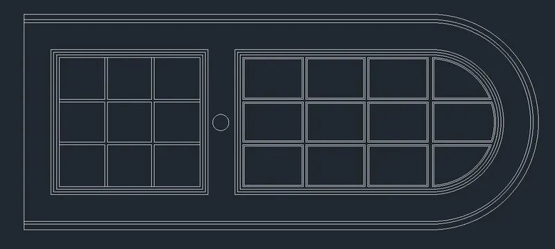
D4.
Step-4:
- type rec and give dimensions 6'10" x 3'4"
- type explode and explode the rec
- erase the left verticalline
- type arc make arc joining two lines
- type o for offfset
- give offset of 5" to innermost rectangle
- then give the offset of 0.5 continuosly for 3 times
- type ddptype select point style
- use divide command to divide in 3 segemnet inner rectangle
- join the line using ortho on
- give the offset of 0.25 at each side to this vertical line
- erse the original vertical lines
- now trim the corner
- and give offset of 0.25 to each rectangle
- beside this panel make other rec and give offset
- offset of 0.5,0.5,0.5,2,0.5
- at middle draw circle using c comand
- use same process and make other panel
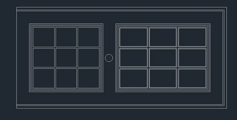
D5.
STEP-5 :
- copy the 2nd number drawing
- trim the unwanted line
- type ddptype select point style
- use divide command to divide in 3 segemnet inner rectangle
- join the line using ortho on
- give the offset of 0.25 at each side to this vertical line
- erse the original vertical lines
- now trim the corner
- and give offset of 0.25 to each rectangle
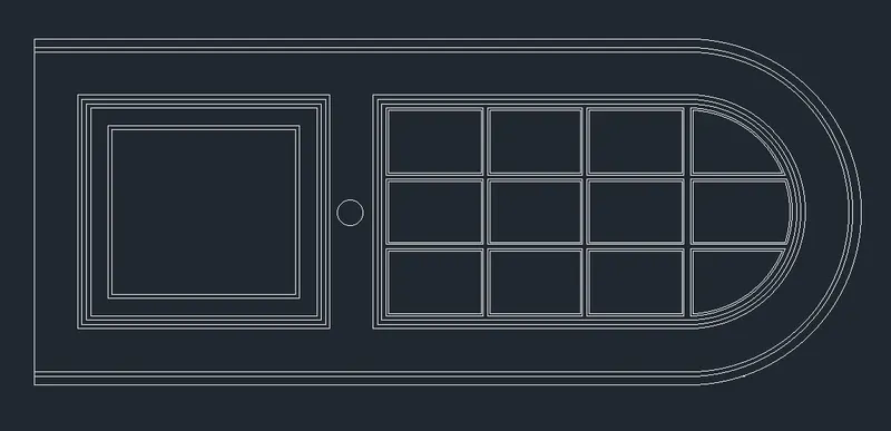
D6.
step-6:
- copy the D4 digram
- type trim and trim the square
- give offset of 2" to innermost rectangle
- then offset of 0.5"
step-7 :
- convert it into block
- type b for block
- give title> select object > pick point . ok
RESULT :
Create the door type for residential building as a block D1,D2,D3,D4,D5,D6
5.DIAGRAM
AIM:
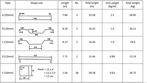
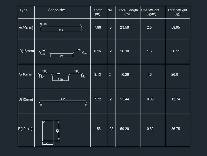
Create each shape as a block as shown in the Figure. Save the block and insert them on the table as shown in the Figure.
INTRODUCTION :
Bar bending schedule or schedule of bars is a tabular representation of reinforcement bar. it is represented of each type of RCC work. with the help of bar bending schedule the requirement of different length and sizes of bar may be known and can be arranged.
PROCEDURE :
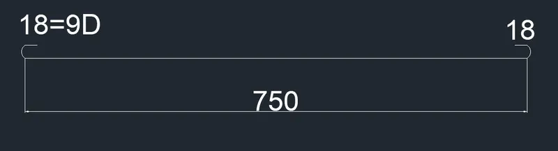
step-1 :
- type un for unit
- set unit > decimal milimeter
- type l for line comand
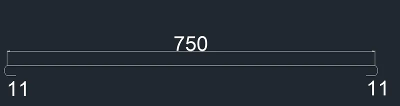
- make horizontal line of distance 750
- make offset to this line
- type arc give arc to this line
- using dimlin give dimension to the line
- type mtext and give some dimension in text
- type l for line comand
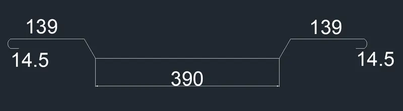
- make horizontal line of distance 390
- make offset to this line >offset of 41
- type line command
- use polar tracking > give angle 60degree to both corner of bottom line
- connect to offset line
- extend the line 180 distance at both sidee
- using trim command erase the unwanted line
- copy the hook from above object and give hook
- using dimlin give dimension to the line
- type mtext and give some dimension in text
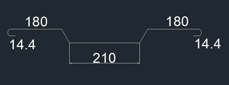
- copy the above object
- just change the horizontal distance of bottom line to 210
- ue trim and move command to do process
- 
- copy the first object
- using mirror command mirrror the fig and erase original object
- erase the text has given
- give new dimension to object using mtext command
-
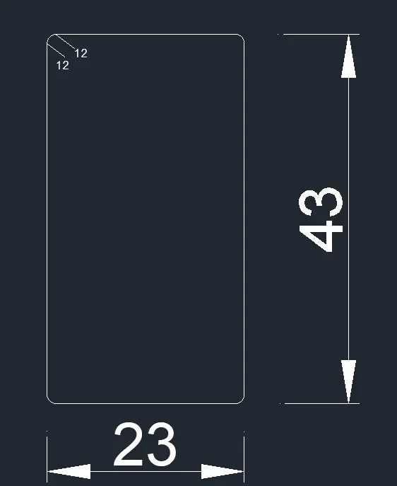
- type rec for rectangle > give dimensions > 43 x 53
- type f for fillet > give radius and fillet corner
- type l command and give line to top left corner
- using dimlin give dimension to the line
- type mtext and give some dimension in text
- finally type b for block and make block of all the above object
- block >type title > select object > pick point > ok
step-2 :
- make table using line offset and trim command
- having 6 rows and 7 columns
- insert the block
- type insert > block > drag oin table
- do this for all block
- using scale command scale nthe block as per table spacing
- type mtext and type text as shown in fig
RESULT :
We Have Created each shape as a block as shown in the Figure. we have Saved the block and inserted them on the table as shown in the Figure.