Creating Bar Bending schedule, Different Door types, and Creation of standard drawing templates using AutoCad
1. Aim: To create the template and title block of the plan of the building the Auto cad using engineering system.
- For everey project or plan of the building we need to create the title block which consists of the name of organisation,architect scale of the drawing and other details of the building.
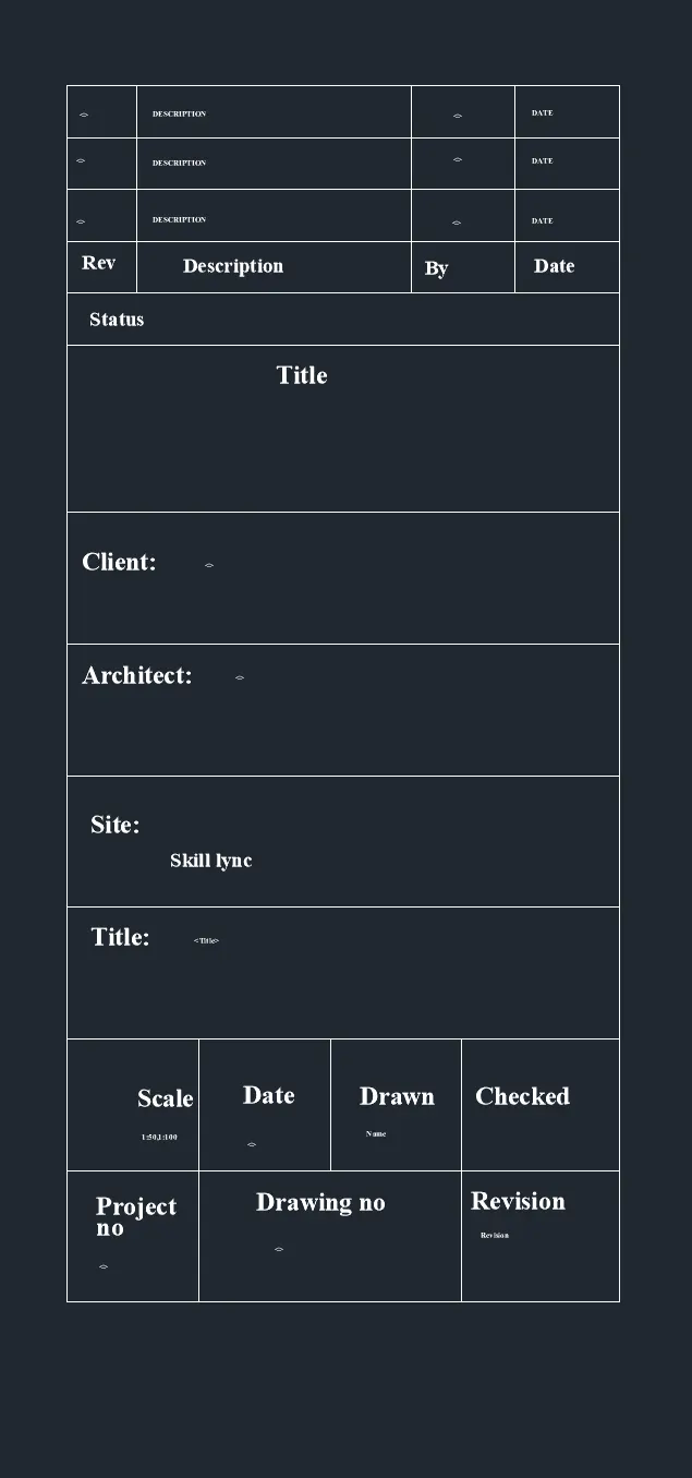
- The title block template consists of the details of client,Architect, plotted concern,checked concern,date of the drawing plotted, Revision number etc which will help ful to know the outlook profile of the drawing.
- The title block also mention about the revision of the drawing.
Procedure :
- Click on new File and create the new template for potting the drawing.
- Now enter units (un) command and select the engineering system in the units and also set the precision of the units and insertion scale to inches and click on ok.
- Firstly we need to plot the plan or elevation of the building and locate the positions of the columns at the specified points.
- The title block and template is prepared by the using the table command in the model space or by default we can create the template using the layout option and we need to edit the title block as we required.
- The template is prepared using the table command and using the merge option we can merge the cells and the details are emcomprised in the table.
- The template created is consisits of more details and the template should be created as block it will be use ful for the further reference of the other drawings.
- Enter text command inthe command bar and eneter the text as drawing no,reference no,site and project no etc at various places of the template and now using the attributes commnad we can enter the tags of the details of the drawing which will helpful to modify and differentiate the template details like drawing no,site,projectno, etc for the various drawings.
- The attributes is nothing but the command used to edit the the various details of a particular block for various drawings.
- Now enter the 'Attdef' in the command bar and eneter the tag,prompt and default details of a particular property of the drawing and place the attribute position at the required position of the drawing.
- Now create the whole template as a block and save it as 'Custom 1_title block'
- When we need to use the title block for two different drawings,we can simply insert the title block and we can edit the properties of the drawing like drawing no,title,project,scale etc for the two different drawings or if we didnot edit any attributes then the template is inserted with the default details which you entered while we defining the attributes.
- The title template is very much useful and mandatory to get to know about the title of the project,scale, revisionnumber, name of the architect etc.
- The title template also contains the special notes which are not mentioned inthe plan or section or elevation etc.
- The final result of the template obtained is shown inthe below.
Aim: To create the template and title block of the plan of the building the Auto cad using engineering system.
- For everey project or plan of the building we need to create the title block which consists of the name of organisation,architect scale of the drawing and other details of the building.
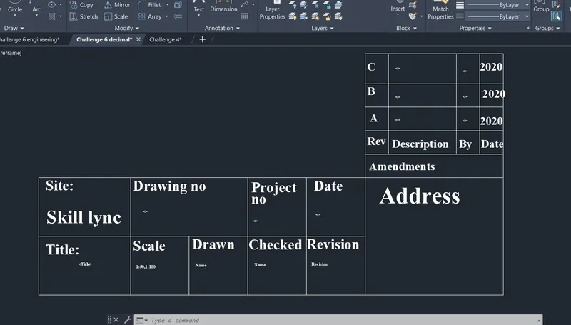
- The title block template consists of the details of client,Architect, plotted concern,checked concern,date of the drawing plotted, Revision number etc which will help ful to know the outlook profile of the drawing.
- The title block also mention about the revision of the drawing.
Procedure :
- Click on new File and create the new template for potting the drawing.
- Now enter units (un) command and select the engineering system in the units and also set the precision of the units and insertion scale to inches and click on ok.
- Firstly we need to plot the plan or elevation of the building and locate the positions of the columns at the specified points.
- The title block and template is prepared by the using the table command in the model space or by default we can create the template using the layout option and we need to edit the title block as we required.
- The template is prepared using the table command and using the merge option we can merge the cells and the details are emcomprised in the table.
- The template created is consisits of more details and the template should be created as block it will be use ful for the further reference of the other drawings.
- Enter text command inthe command bar and eneter the text as drawing no,reference no,site and project no etc at various places of the template and now using the attributes commnad we can enter the tags of the details of the drawing which will helpful to modify and differentiate the template details like drawing no,site,projectno, etc for the various drawings.
- The attributes is nothing but the command used to edit the the various details of a particular block for various drawings.
- Now enter the 'Attdef' in the command bar and eneter the tag,prompt and default details of a particular property of the drawing and place the attribute position at the required position of the drawing.
- Now create the whole template as a block and save it as 'Custom 2_title block'
- When we need to use the title block for two different drawings,we can simply insert the title block and we can edit the properties of the drawing like drawing no,title,project,scale etc for the two different drawings or if we didnot edit any attributes then the template is inserted with the default details which you entered while we defining the attributes.
- The title template is very much useful and mandatory to get to know about the title of the project,scale, revisionnumber, name of the architect etc.
- The title template also contains the special notes which are not mentioned inthe plan or section or elevation etc.
- The final result of the template obtained is shown inthe below.
2.Aim: To create the door of the building in the Auto cad using decimal system.
- Doors and windows are the units of the building which will provide access in to the building and provide the ventilation and circulation of air,light ,sun etc.
- Doors and windows are of different sizes and shapes based on their usage and the materials which are used to prepare.
- The doors may be either wood,glass, Fibre,plywood etc and also the doors may be either single panel or multiple panel based on their cost and size of the doors. for shorter span single span is prefered and for the large span multiple panels are prefered.
- The doors should not be more weight and should be easily handled with out any interruption and it should not undergo any deflectionor deformation due to the load coming from the structure.
Procedure :
- Click on new File and create the new template for potting the drawing.
- Now enter units (un) command and select the decimal system in the units and also set the precision of the units and insertion scale to mm and click on ok.
- Firstly we need to plot the plan or elevation of the building and locate the positions of the columns at the specified points.
- The doors can be plotted according to the sizes mentioned in the plan and it should overlap the plan.
- The door can be plotted by using a poly line command or rectangle command.
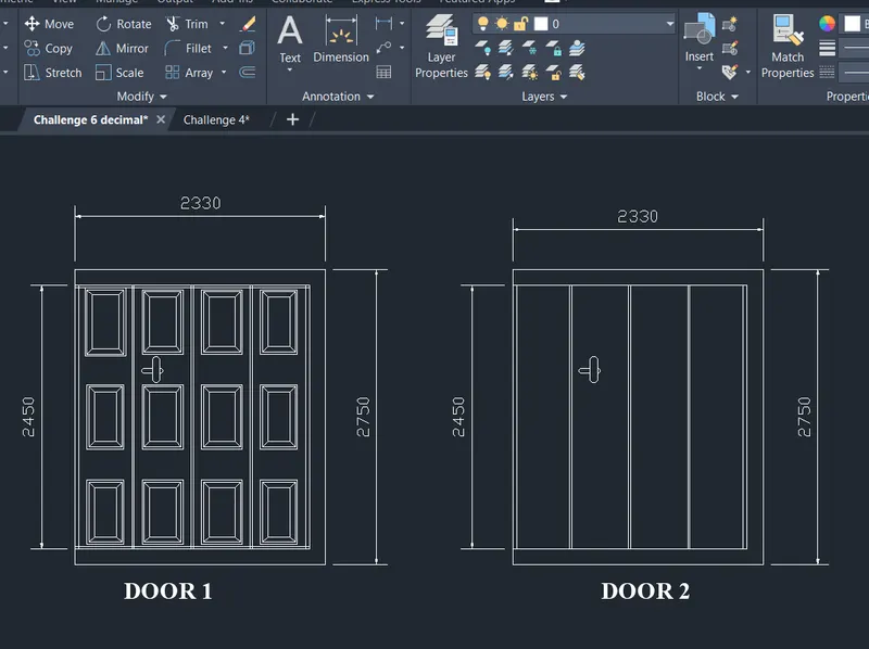
- Enter poly line command and creta the frame of the door whch is fixed to the wall of the building to the size of 2330x2750 which is the outer to outer dimension of the Door.
- Now using the offset command create the frame to a thickness of 50 to 75 mm as we required with an off set distance of 50 to 75mm for both the doors.
- Now the door can be either plane surface or panelled with various rectangular blocks and the plane surface is nothing but the smmoth surface of the door while the small panels can be created with an rectangular command.
- The small panel blocks can be created with a rectanngular command and the y can be arranged in the door surface with the copy command.
- The door handle canbe provided as a block and can be inserted on the door surface around 1100 to 1200mm from the bottom surface of the door.
- Enter dim linear command and measure the dimensions of the door.
- The final result of the doors obtained is shown inthe below.
3.Aim: To create the utilities models of the building in the Auto cad using decimal system.
- Every bulding consits of various utilities which will fullfill the requirements of the house mates.
- The utilities may be either electrical,plumbing or furniture etc.In a particular building there will be the various utilities which may be electrical,plumbing or furniture etc or may be combined. It may create the problem for the designer or the architect to draw the various number of utilities for each and every drawing.So they plot the utilities separately and insert them in the plan where they required.
- The utilities plotted are created as blocks and can be used for the various drawings or layouts.
Procedure :
- Click on new File and create the new template for potting the drawing.
- Now enter units (un) command and select the decimal system in the units and also set the precision of the units and insertion scale to mm and click on ok.
- Firstly we need to plot the plan or elevation of the building and locate the positions of the columns at the specified points.
- After th plotting the plan it is mandatory to provide the elctrical plumbing and furniture layout of the particular plan of the building which will help to locate the position of the utilities.
- The utilites may lights,switches,sockets and shandliers etc.
- The utilities are provided with individual symbol which will get to know about the nature of utility when we identify in a particular plan.
- The utilites are plotted separately in the model space and they are created as individual blocks which will be easy for the designer to insert them at the various positions of the plan.
- The utilities are plotted separately and enter block in the command bar and they are created as a block with the specfic point as the orientation.
- The blocks can be inserted and edit according to the plan requirement and the scale of the block is also modified.
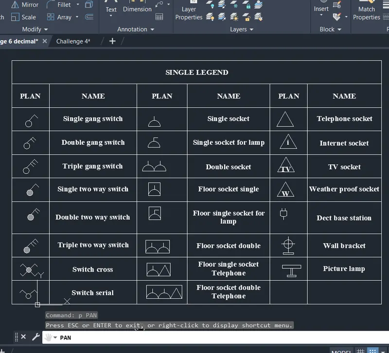
- After the insertion of the utilities in the plan as a blocks we need to prepare a table by listing the utilities in the drawing.
- The Table is created using a table option in the annotation bar and the the utilities which are inserted in the plan must be copied or inserted agin in the table and the name of the utility should be mentioned in the table.
- This will help for the unskilled persons also to get to know about the details of the utilities provided in the plan of the building.
- The final result of the utilities is obtained as shown inthe below.
4.Aim: To create the various doors of the building in the Auto cad using decimal system.
- Doors and windows are the units of the building which will provide access in to the building and provide the ventilation and circulation of air,light ,sun etc.
- Doors and windows are of different sizes and shapes based on their usage and the materials which are used to prepare.
- The doors may be either wood,glass, Fibre,plywood etc and also the doors may be either single panel or multiple panel based on their cost and size of the doors. for shorter span single span is prefered and for the large span multiple panels are prefered.
- The doors should not be more weight and should be easily handled with out any interruption and it should not undergo any deflectionor deformation due to the load coming from the structure.
Procedure :
- Click on new File and create the new template for potting the drawing.
- Now enter units (un) command and select the decimal system in the units and also set the precision of the units and insertion scale to mm and click on ok.
- Firstly we need to plot the plan or elevation of the building and locate the positions of the columns at the specified points.
- The doors can be plotted according to the sizes mentioned in the plan and it should overlap the plan.
- The door can be plotted by using a poly line command or rectangle command.
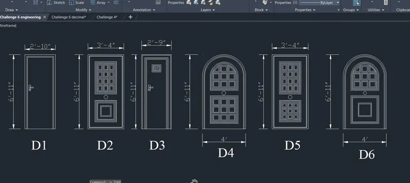
- Enter poly line command and creta the frame of the door whch is fixed to the wall of the building to the size of D1(6'11"X2'10"),D2(6'11"X3'4"),,D3(6'11"X2'9"),D4(6'11"X4'),D5(6'11"X3'4")D6(6'11"X4') which is the outer to outer dimension of the DoorS.
- Now using the offset command create the frame to a thickness of 50 to 75 mm as we required with an off set distance of 50 to 75mm for both the doors.
- Now the door can be either plane surface or panelled with various rectangular blocks and the plane surface is nothing but the smmoth surface of the door while the small panels can be created with an rectangular command.
- The doors D4 and D6 are made of curve shape at the top portion of the door and it can be plotted using arc command option start end centre of the arc.
- The small panel blocks can be created with a rectanngular command and the y can be arranged in the door surface with the copy command.
- The door handle canbe provided as a block and can be inserted on the door surface around 1100 to 1200mm from the bottom surface of the door.
- Enter dim linear command and measure the dimensions of the door and using the text command we can mention the door as D1,D2,D3,D4,D5,D6 etc.
- The final result of the doors obtained is shown inthe below.
5.Aim: To create the door of the building in the Auto cad using decimal system.
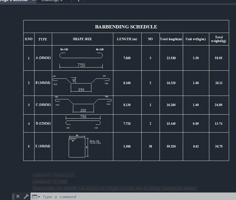
- Barbending schedule is the schedule of the reinforcemnet bars with size,shape of the bars of the various units of the building lokee beam,column,footing,slab etc.
- This schedule helps to know about the quantity of the steel required for the building and the sizes of the bars and the number of bars required for the unit like beam,column or any other unit.
- It also helpful to avoid watage of bars while cutting and binding the reinforcement.
- BBS helps for steel inspection to check the reinforcement of a building unit .
- It helps for the barbenders to cut and bend the bars with out any confusion.
Procedure :
- Click on new File and create the new template for potting the drawing.
- Now enter units (un) command and select the decimal system in the units and also set the precision of the units and insertion scale to mm and click on ok.
- Firstly we need to plot the plan or elevation of the building and locate the positions of the columns at the specified points.
- The lyout plan of the building units are plotted like the column and footing lay out,plinth beam lay out,roof bem and slab layout etc.
- The BBS is prepared for each layout will help the barbenders to know about the deatils of various bars of various sizes and shapes and also provide the quantity of sttel required.
- The bar bending schedule is prepared in tabular form.Inthis table the various of sizes,shape, count of the bars and weight of the bars is provided.
- Using the annotation units the table can be inserted with the specified rows and columns.In the table the title bar is mentioned with the Barbending schedule of particular lay out which may be footing,plinth beam.roof or slab etc.
- The various bars in the particular layout is provided with a mark like A,B,C,D,E etc for the various diameters of the bars.The shape of the bars can be plotted separately and they are created as blocks and they are inserted in the table at their respective mark.
- The Barbending schedule also provides the unit weight of the bars and the total weight of the rein forcement of the bars required for the particular lay out.
- The final result of the barbending schedule is obtained as shown inthe below.