Creating Bar Bending schedule, Different Door types, and Creation of standard drawing templates using AutoCad
Aim - i) To create the template by using Text and Attributes .
ii) To create Custom1_titleblock and Custom2_titleblock by using Attributes .
Introduction - i) In Autocad standard templates are given in Start tab
ii) Templates helps you to create future drawings without initial settings .
iii) It reduces the work time and also reduces the chance to make mistakes in settings .
iv) Followings commands are used -
a) Line
b) Rectangle
c) Block
d) Attributes
e) Text
f) Insert
Procedure -
A) Custom1_titleblock -
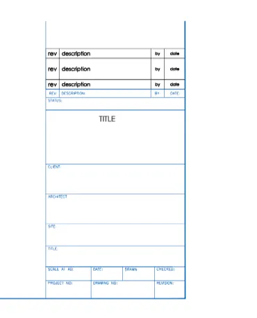
Step by step procedure
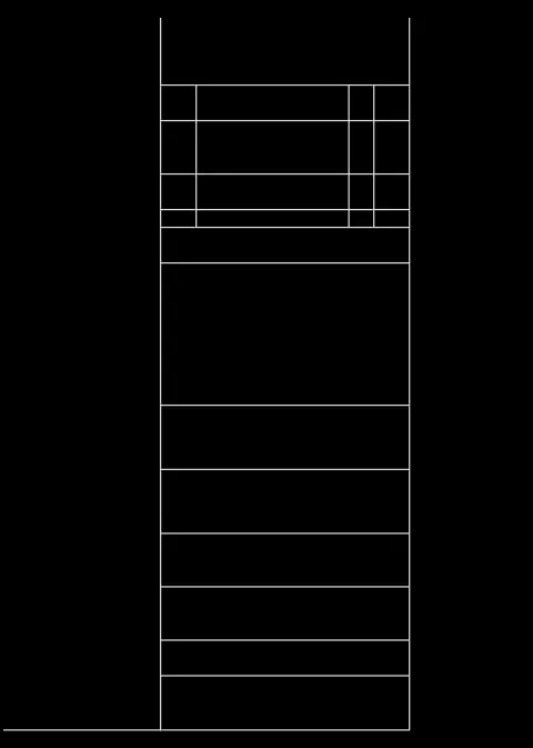
Step 1) To create rows and columns .
i) To draw the template give command Rectangle.
ii) Enter the length = 70mm
iii) Enter width = 200mm
iv) Take the offset of 15mm to draw the 1st row from the bottom .
v) Similarly take offset of 10mm , 15mm , 15mm , 18mm , 18mm , 40mm , 10mm , 5mm , 10mm , 15mm,
10mm .
vi) Simlarly for columns take offset 10mm from both sides and take 8mm from 10mm offset .
Step 2) Create a text
i) Command DT
ii) Justify - Left
iii) Style - Arial
iv) Specify text point
v) Text ht - 2 mm
vi) Text angle - 0
vii) Press Enter .
viii) Write the text as shown in template .
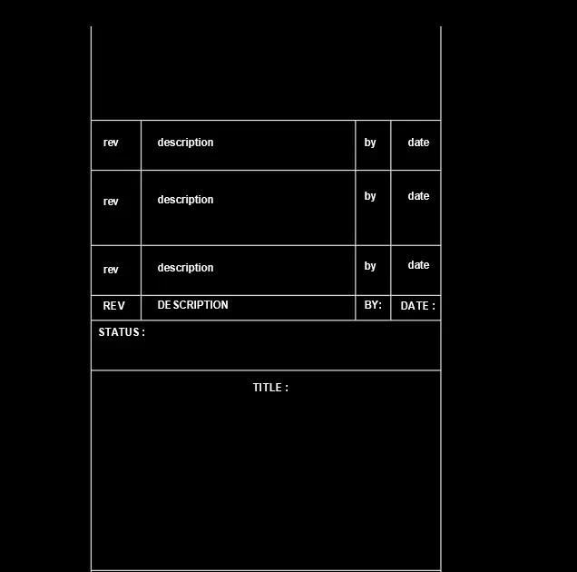
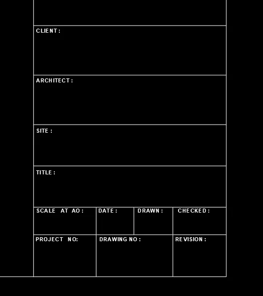
Note - i) Change the layer of rows as shown in fig .
( Directly it can be done by selecting the line and right click - properties - colour )
ii) Command MA and give this properties to other rows , columns and text also .
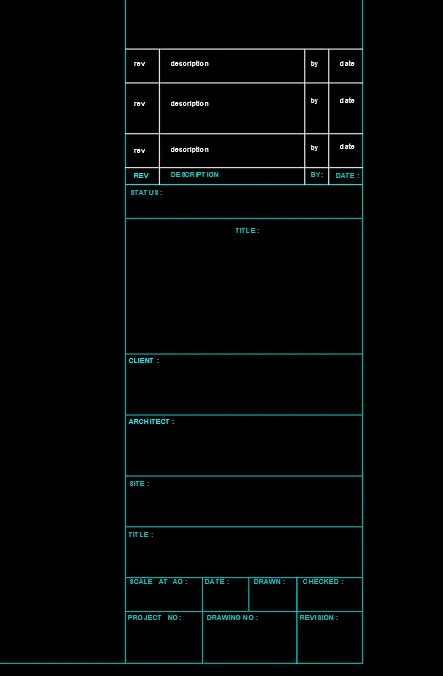
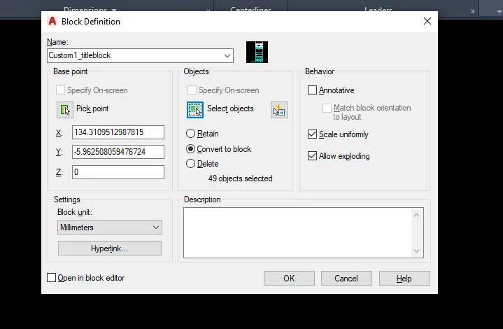
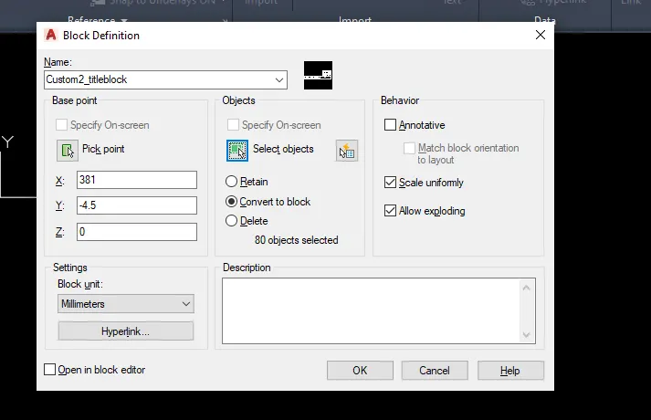
Step 3) Create a block -
i) Command B
ii) Name it as Custom1_titleblock
iii) Pick up point .
iv) Select the whole object
v) Convert into the block .
B) Custom2_titleblock -
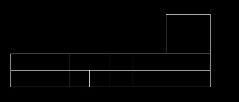
Step 1) Create the rows and columns.
i) Comand Rectangle
ii) Enter the length = 400mm
iii) Enter width = 75 mm
iv) Take the offset of 37.5mm to draw the 1st row from the bottom
v) Similarly for columns take offset of 120mm , 80mm , 40mm , 40mm
Step 2) Create a text -
i) Command DT
ii) Justify - Left
iii) Style - Arial
iv) Specify text point
v) Text ht - 5 mm
vi) Text angle - 0
vii) Press Enter .
viii) Write the text as shown in template .
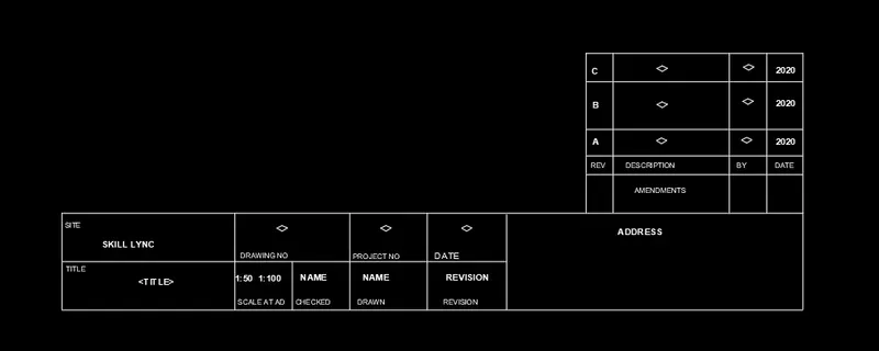
Step 3) Create a block -
i) Command B
ii) Name it as Custom2_titleblock
iii) Pick up point .
iv) Select the whole object
v) Convert into the block
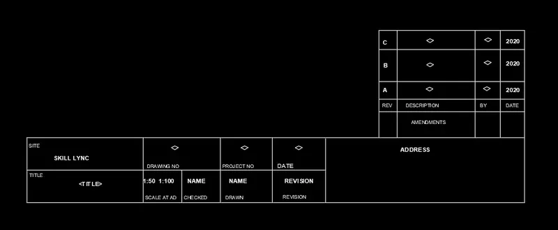
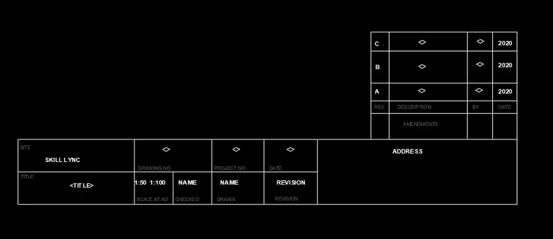
Result - 1) The Custom1_titleblock is created .
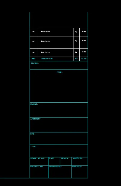
2) The Custom2_titleblock is created .
2)
Aim - To create the door type for warehouse and create them into the blocks .
Introduction - 1) Door Size
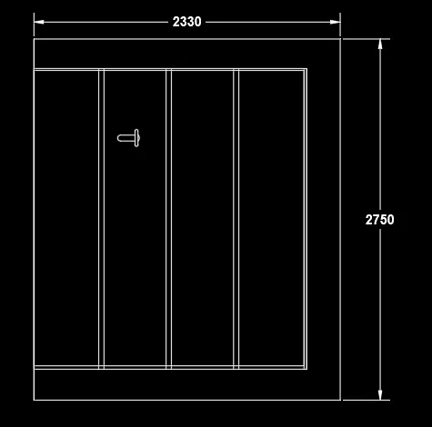
i) Door 1 - 2330 x 2750 mm
ii) Door 2 - 2330 x 2750 mm
Procedure -
i) Open a new drawing (Cntrl + N) with metric units
ii) Select units to Decimal and Precision (0.0) with Milimeters .
iii) Lim-max and limits are also set .
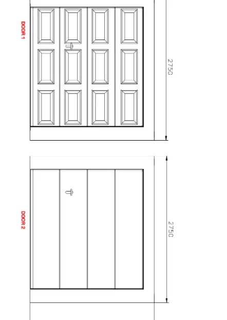
Step by Step procedure -
Step 1) Create a rectangle
i) Command Rectangle
ii) Enter length = 2330 mm
iii) Enter width = 2750mm

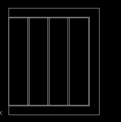
Step 2)
i) Command Offset
ii) Give offset of 100 mm from right side and 150mm from top and bottom .
iii) Divide the remaining portion into 4 parts
iv) Command DIV
v) Enter the number of segments = 4
vi) Draw the vertial lines from divide points .
vii) Take the offset of 20mm on both side .
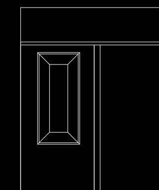
Step 3) Create a door -
i) Create a rectangle
ii) Enter length - 280mm
iii) Enter width - 600mm
iv) Command offset 20mm
v) Command offset - 80mm .
Step 4)
i) Command Array .
ii) Select object - Door
iii) Enter no of columns - 4
iv) Enter no of rows - 3
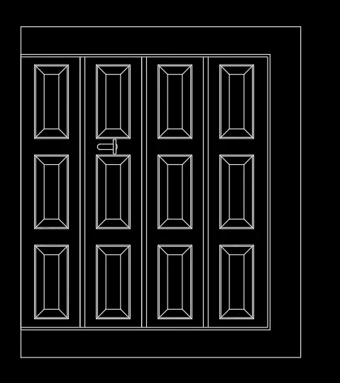
Step 5) Dimensions and Annotations .
i) Command D
ii) Modify units - Select primary units - select precision 0
iii) Fit - Use overall Scale - 400
iv) Command Dim
v) Measure the dimensions .
vi) Command DT
vii) Justify - Left
viii) Style - Arial
ix) Specify text point
x Text ht - 150 mm
xi) Text angle - 90
xii) Press Enter .
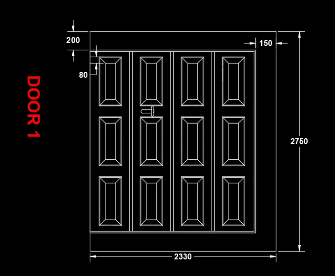
Step 6) Create a block -
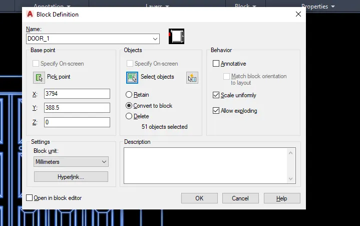
i) Command B
ii) Name it as DOOR_1
iii) Pick up point .
iv) Select the whole object
v) Convert into the block
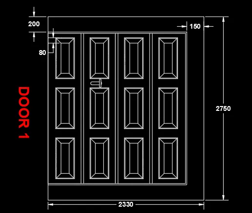
Step 7) Door 2 -
i) Take the vertical projection of Door 1
ii) Command XL - Vertical
iii) Draw the horizontal line at the distance of 2750mm from bottom
iv) Take the projections of inner vertical lines .
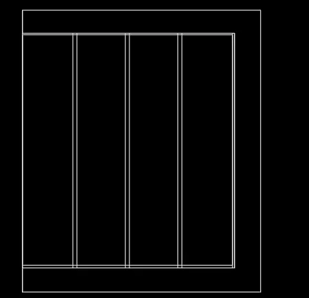
Step 8)
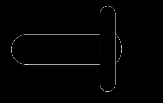
i) Command Rec
ii) Enter length - 200mm
iii) Enter width - 100mm
iv) Command Fillet - Join the curves of recrangle
v) Draw the two line parallel to each other
vi) Command Fillet - and join the lines .
Step 9) Create a block of DOOR_2
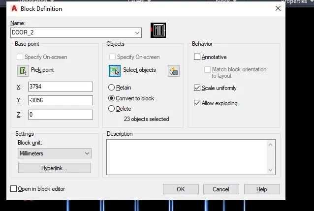
i) Command B
ii) Name it as DOOR_2
iii) Pick up point .
iv) Select the whole object
v) Convert into the block
Results -
1) The Door 1 block is created
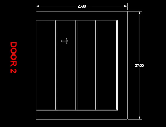
2) The Door_2 block is created .
3)
Aim - To create a electric symbols as a block and arrange them in a legend .
Introduction - i) Electrical symbols are used to show the electrical items .
ii) We cannot draw or create a electrical plan everytime to show or locate the positions
of electricals items.
iii) So In that cases this symbols are helpful .
iv) Followings are the command used -
a) Line
b) Circle
c) Arc
d) Trim
e) Offset
f) Copy
g) Field
h) Block
Procedure -
i) Open a new drawing (Cntrl + N) with metric units
ii) Select units to Decimal and Precision (0) with Milimeters .
iii) Lim-max and limits are also set .
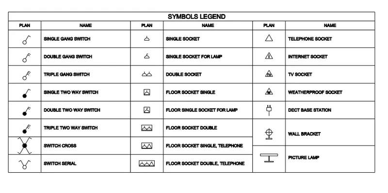
Step by Step Procedure -
Step 1) Create a Electrical Switches Individually .
A) Single Gang Switch -
i) Command Circle - Radius 50mm
ii) Command line -Draw a inclined line of 30mm and draw a perpendicular line to inclined line of 10mm

B) Double Gang Switch -
i) Command Circle - Radius 50mm
ii) Command line -Draw a inclined line of 30mm and draw a two perpendicular line to inclined line of 10mm

C) Triple Gang Switch -
i) Command Circle - Radius 50mm
ii) Command line -Draw a inclined line of 30mm and draw a three perpendicular line to inclined line of 10mm
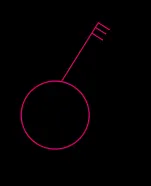
D) Single Two way switch -
i) Command Circle - Radius 50mm
ii) Command line -Draw a inclined line of 30mm and draw a perpendicular line to inclined line of 10mm
iii) Command Hatch - Solid fill and Press Enter .

E) Double Two way switch -
i) Command Circle - Radius 50mm
ii) Command line -Draw a inclined line of 30mm and draw a two perpendicular line to inclined line of 10mm
iii) Command Hatch - Solid fill and Press Enter .

F) Triple two way switch
i) Command Circle - Radius 50mm
ii) Command line -Draw a inclined line of 30mm and draw a three perpendicular line to inclined line of 10mm
iii) Command Hatch - Solid fill and Press Enter .
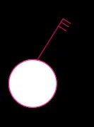
G) Switch Cross
i) Command Circle - Radius 50mm
ii) Command line -Draw a diagonal line of 60mm and draw a perpendicular line to diagonal line of 10mm
iii) Command Hatch - Solid fill and Press Enter .
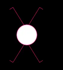
F) Switch Serial -
i) Copy the Switch Cross Symbol
ii) Command Trim
iii) Trim the bottom lines
iv) Command Hatch - No fill .

G) Single Socket -
i) Command Line - 30mm
ii) Command Arc - to draw the arc
iii) Command line - Draw a vertical line of 10mm from center of arc .
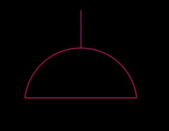
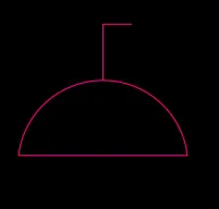
H) Single Socket for Lamp -
i) Command Line - 30mm
ii) Command Arc - to draw the arc
iii) Command line - Draw a vertical line of 10mm from center of arc .
iv) Command line - draw a horizontal line of 5mm from vertical line
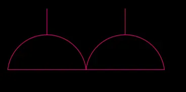
I) Double Socket -
i) Command Copy - Copy the Single Socket
ii) Specify the base point and copy it
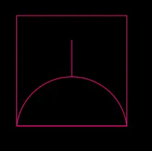
J) Floor Socket -
i) Command Copy - Copy the Single Socket
ii) Command Rec -
iii) Enter Length - 30
iv) Enter width - 30
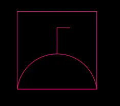
k) Floor Single Socket For Lamp
i) Command Copy - Copy the Single Socket for lamp
ii) Command Rec -
iii) Enter Length - 30
iv) Enter width - 30
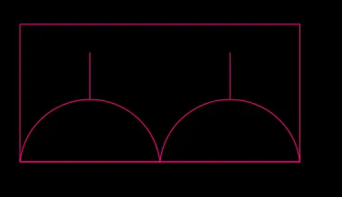
L) Floor Socket Double -
i) Command Copy - Copy the Double Socket
ii) Command Rec -
iii) Enter Length - 60
iv) Enter width - 30
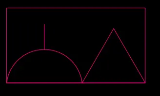
M) Floor Socket single , Telephone
i) Command Polygon - Enter sides 3
ii) Command Copy - Copy the Single Socket
iii) Command Rec -
iii) Enter Length - 60
iv) Enter width - 30
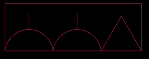
N) Floor Socket Double , Telephone
i) Command Copy - Copy the Floor Socket Double
ii) Copy the Polygon which we have created earlier
iii) Specify the base point and paste it .
O) Telephone Socket -
i) Command Copy - Copy the polugon which we have created earlier
ii) Specify the base point and paste it

P) Internet Socket
i) Command Copy - Copy the Telephone Socket
ii) Command T - and give text as i

Q) TV socket
i) Command Copy - Copy the Telephone Socket
ii) Command T - and give text as TV

R) Weatherproof Socket
i) Command Copy - Copy the Telephone Socket
ii) Command T - and give text as w

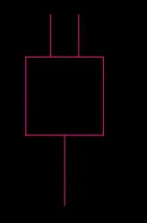
S) DECT Base Station
i) Command Rec -
ii) Enter length - 10mm
iii) Enter width - 1mm
iv) Command line - draw two vertical line at the top of 5mm and and at bottom 15mm at the center .
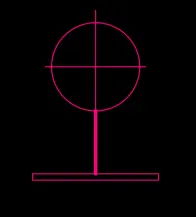
T) Wall Socket
i) Command Rec -
ii) Enter length - 10mm
iii) Enter width - 1mm
iv) Draw a vertical line of 5mm
v) Draw a circle of 20mm and draw the perpendicular line from the center of circle
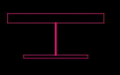
U) Picture lamp
i) Command Rec -
ii) Enter length - 20mm
iii) Enter width - 2mm
iv) Draw a vertical line of 5mm
v) Command Rec -
vii) Enter length - 10mm
viii) Enter width - 1mm
Step 2) Create a block -
i) Command B
ii) Name it as Single_Gang_Switch
iii) Pick up point .
iv) Select the whole object
v) Convert into the block
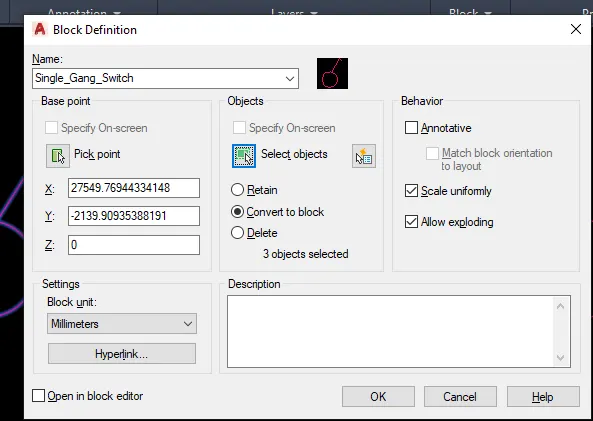
vi) Similarly Convert all other symbols into the block and saved it with the following names -
- Single_Gang_Switch
- Double_Gang_Switch
- Triple_Gang_Switch
- Single_Twoway_Switch
- Double_Twoway_Switch
- Triple_Twoway_Switch
- Switch_Cross
- Switch_Serial
- Single_Socket
- Single_Socket_For_Lamp
- Double_Socket
- Floor_Socket_Single
- Floor_Single_Socket_For_Lamp
- Floor_Socket_Double
- Floor_Socket_Single_Telephone
- Floor_Socket_Double_Telephone
- Telephone_Socket
- Internet_Socket
- TV_Socket
- Weatherproof_Socket
- DECT_Base_Station
- Wall_Bracket
- Picture_Lamp
Step 3) Create a table
i) Create a table Command Table
ii) Enter columns = 6
iii) Enter rows = 10
iv) Press Enter .
Step 4) Create a Symbols Legends -
i) Command Insert
ii) Insert the blocks in the table one by one
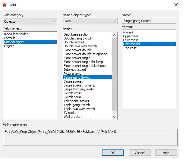
iii) Command Field - Name Object - Block - and Select name
iv) Place the text infront of their symbols .
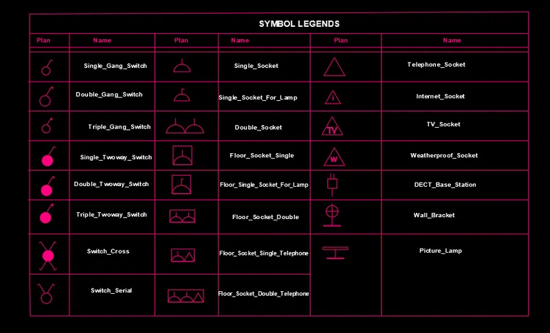
Results - All the Electricals Symbols are created as a blocks and arranged them as shown in fig .
4)
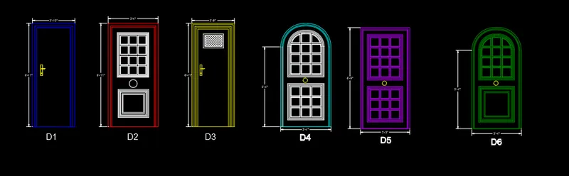
Aim - To create the door type for residential building as a block and save it as a blocks .
Introduction - i) There are six doors are given with dimensions
a) D1 - 2'10" x 6'11"
b) D2 - 3'4" x 6'11"
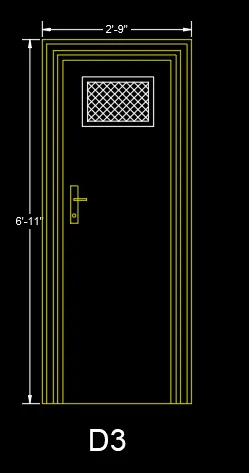
c) D3 - 2'9" x 6'11"
ii) Following Commands are used -
a) Line
b) Arc
c) Offset
d) Rec
e) Trim
f) Dtext
g) Dim
Procedure -
i) Open a new drawing (Cntrl + N) with imperical units
ii) Select units to Engineeering and Precision (0'.0") with inches .
iii) Lim-max and limits are also set .
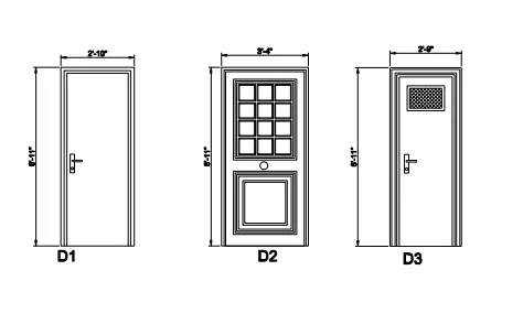
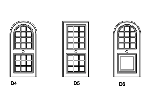
A) Door 1
Step 1)
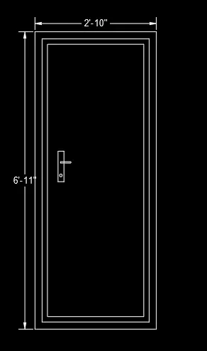
i) Command Rec -
ii) Enter length - 2'10"
iii) Enter width - 6'11"
iv) Command Offset - Take offset of 2"
v) Again take offset of 1.5"
vi) Draw a rec with approximate size for handle .
vii) Draw a circle with dia - 1"
Step 2) Change the layer and Annotations
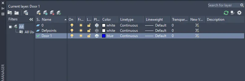
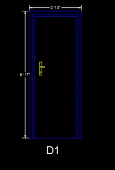
i) Command LA
ii) Name it as - Door 1 - Select colour
iii) Command DT
iv) Justify - left
v) Select text ht - 5"
vi) Text angle - 0
vii) Specify the point
viii) Press Enter
Step 3) Create a block
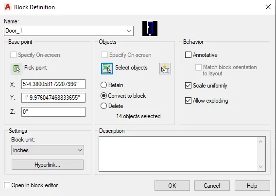
i) Command B
ii) Enter the Name - Door_1
iii) Select pick point of the door
iv) After pick point select the whole object
v) Press Enter
vi) Now we have to turn on the scale uniformity
vii) Now Convert into block
viii) Press Ok
B) Door 2 -
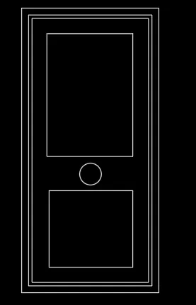
Step 1)
i) Command Rec -
ii) Enter length - 3'4"
iii) Enter width - 6'11"
iv) Command Offset - Take offset of 2"
v) Again take offset of 1"
vi) Again Command Rec ( To draw a inner portion )
vii) Enter length - 2'1"
viii) Enter width - 3'
ix) For Bottom portion - draw rec of 2' x 1'10"
x) Press Enter .
xi) Command Circle - Dia -6" and draw the circle .
Step 2)
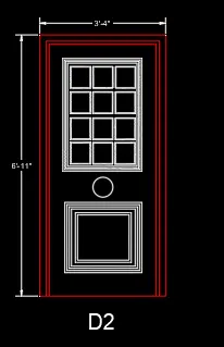
i) Take the offset - 0.2" for 3 times .
ii) Draw the inner Square of size 6" x 6"
iii) Command Array -
iv) Columns - 3
v) Rows - 4 and draw the inner portion .
vi) For Bottom portion - Take offset of 0.7" for 4 times , then 1.2" and 0.7"
vii) Press Enter
Step 3) Create a block
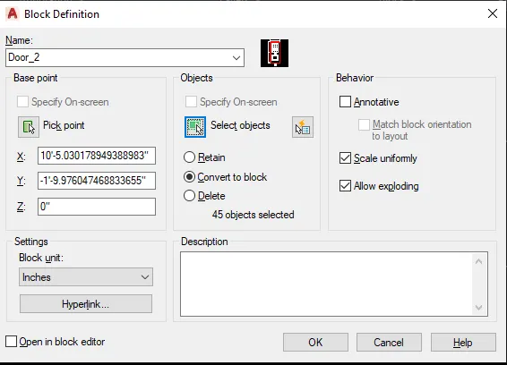
i) Command B
ii) Enter the Name - Door_2
iii) Select pick point of the door
iv) After pick point select the whole object
v) Press Enter
vi) Now we have to turn on the scale uniformity
vii) Now Convert into block
viii) Press Ok
C) Door 3
Step 1)
i) Command Rec -
ii) Enter length - 2'9"
iii) Enter width - 6'11"
iv) Command Offset - Take offset of 1"
v) Again take offset of 1.5"
vi) Again take offset of 1"
vii) Again take offset of 1.2"
viii) Draw a rectangle of size 1' x 11" at the top
ix) Commmand hatch -select pattern - ANSI137
x) Select internal point and do the hatching .
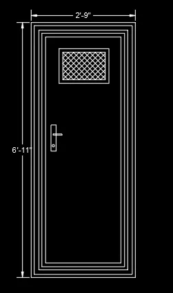
xi) Trim the unwanted lines
xii) Follow the same procedure for applying layers and annotations
Step 2) Create a block
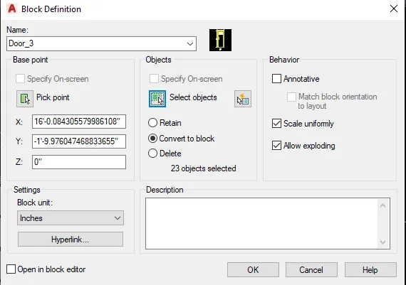
i) Command B
ii) Enter the Name - Door_3
iii) Select pick point of the door
iv) After pick point select the whole object
v) Press Enter
vi) Now we have to turn on the scale uniformity
vii) Now Convert into block
viii) Press Ok
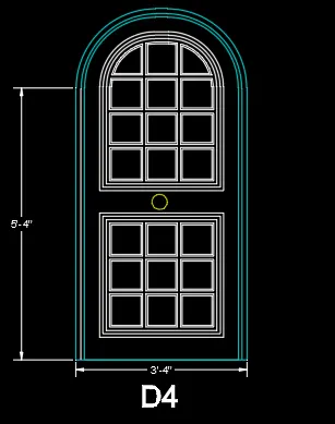
D) Door 4
Step 1)
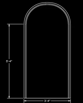
i) Command Rec -
ii) Enter length - 3'4"
iii) Enter width 5'4"
iv) Command Arc - Start end radius .
v) Draw the arc of radius - 1'8"
vi) Take the offset of 1" and 0.5" .
Step 2)
i) Draw the rectangle - 2'5" x 2"
ii) Command Arc - and enter radius 1'2" and draw the arc
iii) Take offset of 1" for 3 times .
Similarly
iv) At bottom side also draw a rectangle of 2'5" x 2'5"
v) Take the offset 1" for 3 times
vi) Follow the same procedure to draw the inner geometry
vi) Command Array - No of columns - 3
(For upper portion) No of rows - 4
vii) For Bottom portion - No of columns - 3
No of rows - 3
viii) Size of Each Square is 6" x 6" ( Same as Door 2)
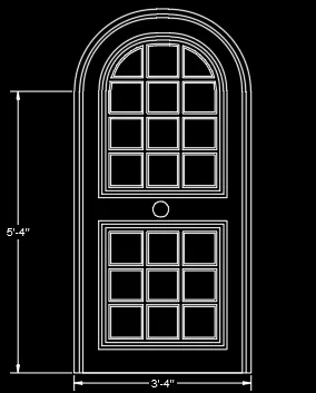
ix) Follow the same procedure for layers and Annotations
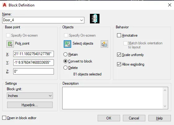
Step 3) Create a block
i) Command B
ii) Enter the Name - Door_4
iii) Select pick point of the door
iv) After pick point select the whole object
v) Press Enter
vi) Now we have to turn on the scale uniformity
vii) Now Convert into block
viii) Press Ok
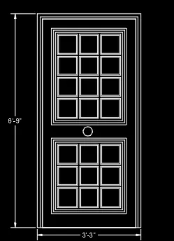
E) Door 5 -
Step 1)
i) Command Rec -
ii) Enter length - 3'4"
iii) Enter width -6'11"
iv) Command Offset - Take offset of 2"
v) Again take offset of 1"
vi) Again Command Rec ( To draw a inner portion )
vii) Enter length - 2'1"
viii) Enter width - 3'
ix) For Bottom portion - draw rec of 2' x 1'10"
x) Press Enter .
xi) Command Circle - Dia -6" and draw the circle .
Step 2)
i) Take the offset - 0.2" for 3 times .
ii) Draw the inner Square of size 6" x 6"
iii) Command Array - For Upper Portion
iv) Columns - 3
v) Rows - 4 and draw the inner portion .
vi) For Bottom portion - Take offset of 0.7" for 4 times , then 1.2" and 0.7"
Command Array - To draw a square at bottom side
vii) For Bottom portion - No of columns - 3
No of rows - 3
viii) Size of Each Square is 6" x 6" .
ix) Change tha layer colour and give Annotations
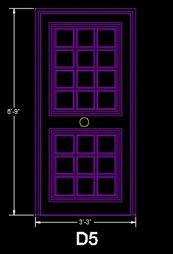
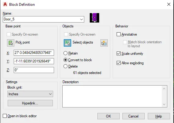
Step 3) Create a block
i) Command B
ii) Enter the Name - Door_5
iii) Select pick point of the door
iv) After pick point select the whole object
v) Press Enter
vi) Now we have to turn on the scale uniformity
vii) Now Convert into block
viii) Press Ok
F) Door 6
Step 1)
i) Command Rec -
ii) Enter length - 3'4"
iii) Enter width 5'4"
iv) Command Arc - Start end radius .
v) Draw the arc of radius - 1'8"
vi) Take the offset of 1" and 0.5" .
Step 2)
i) Draw the rectangle - 2'5" x 2"
ii) Command Arc - and enter radius 1'2" and draw the arc
iii) Take offset of 1" for 3 times .
Similarly
iv) At bottom side also draw a rectangle of 2'5" x 2'5"
v) Take the offset 1" for 3 times
vi) Follow the same procedure to draw the inner geometry
vi) Command Array - No of columns - 3
(For upper portion) No of rows - 4
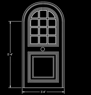
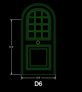
vii) Change the layer and give the annotations
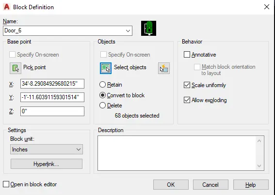
Step 3) Create a block
i) Command B
ii) Enter the Name - Door_6
iii) Select pick point of the door
iv) After pick point select the whole object
v) Press Enter
vi) Now we have to turn on the scale uniformity
vii) Now Convert into block
viii) Press Ok
Results - All the door type for residential building are created as a blocks .
5)
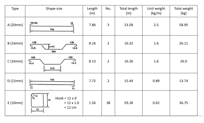
Aim - To create the Bar shape as a block and arrange them in a table .
Introduction - i) Bar Bending Schedule gives an overall idea of Reinforcement .
ii) BBS includes marks of reinforcement , shape , size , cutting length etc.
iii) It is helpful for Structural Engineer while doing the structural audit .
iv) Following Commands are used -
a) Line
b) Rec
c) Offset
d) Rec
e) Trim
f) Dtext
g) Dim
h) Fillet
i) Block
Procedure -
i) Open a new drawing (Cntrl + N) with metric units
ii) Select units to Decimal and Precision (0) with Milimeters .
iii) Lim-max and limits are also set .
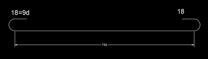
Step 1) Type A
i) Command Line
ii) Draw the line of 750 mm
iii) To draw the hooks - Draw a circle of radius 25mm and draw the two horizontal line at top and bottom
iv) Trim the remaining portions

v) Copy the hooks at the end of the 750mm line


vi) Command Dim - Measure the dimensions of line
vii) Command text and give the text where required .
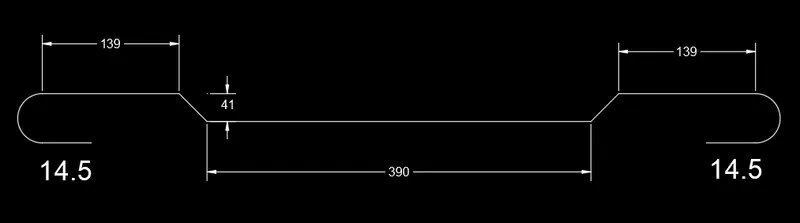
Step 2) Type B
i) Command line
ii) Draw the line of 390mm
iii) Copy the hooks from previous type
iv) Draw the inclined line from both the end of 390mm line
v) Again draw the line of 139mm from both the sides from inclined line
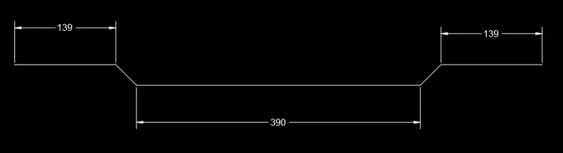
vi) Copy the hooks at the end of 139mm line on both sides .
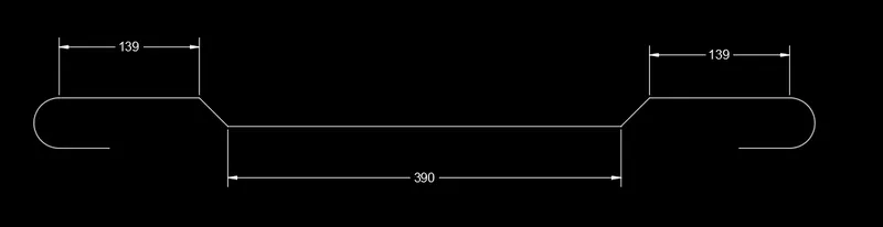
vii) Give the text and measure the dimensions by using command Dim
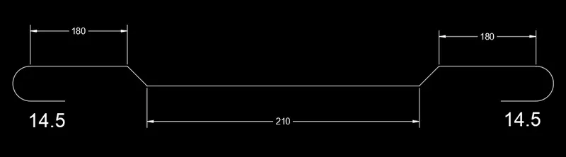
Step 3) Type C
i) Command line
ii) Draw the line of 210 mm
iii) Copy the hooks from previous type
iv) Draw the inclined line from both the end of 210 mm line
v) Again draw the line of 180 mm horizontally from both the sides from inclined line
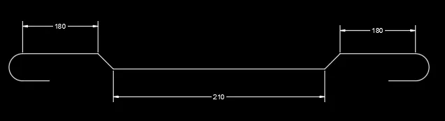
vi) Copy the hooks at the end of 139mm line on both sides .
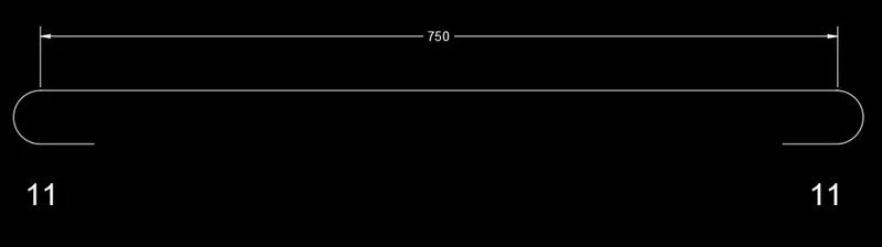
Step 4) Type D
i) Command Line
ii) Draw the line of 750 mm
iii) Draw the hooks samw as we have drawn earlier
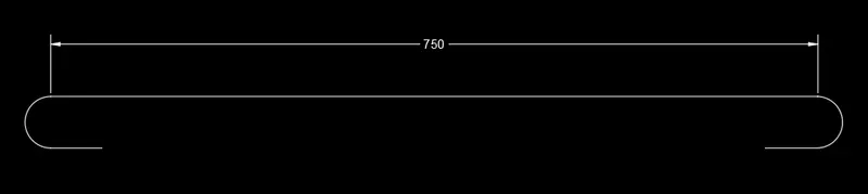
iv) Give the text and measure the dimensions .
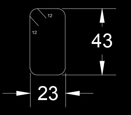
Step 5) Type E
i) Command Rec
ii) Enter Length = 23 mm
iii) Enter width -= 43mm
iv) Command Fillet
v) Enter radius - 5mm
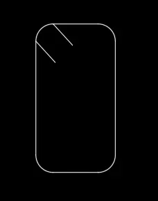
vi) Give the text and measure the dimensions by using command Dim
Step 6) Convert each shape into block -
i) Command B
ii) Enter the Name -Type A
iii) Select pick point of the shape
iv) After pick point select the whole object
v) Press Enter
vi) Now we have to turn on the scale uniformity
vii) Now Convert into block
viii) Press Ok
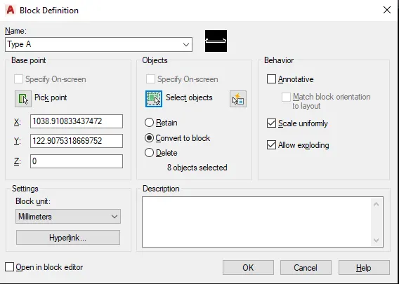
Similaly convert all other shape into blocks by giving name as follows
i) Type A
ii) Type B
iii) Type C
iv) Type D
v) Type E
Step 7) Create a Table
i) Create a table by giving command Table
ii) Enter no of columns as - 7
iii) Enter no of rows as - 6
For Text
i) Command DT
ii) Justify - Center
iii) Style - Arial
iv) Specify text point
v) Text ht - 60 mm
vi) Text angle - 0
vii) Press Enter .
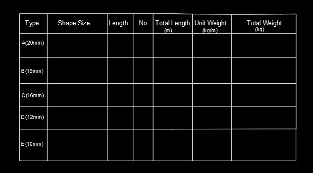
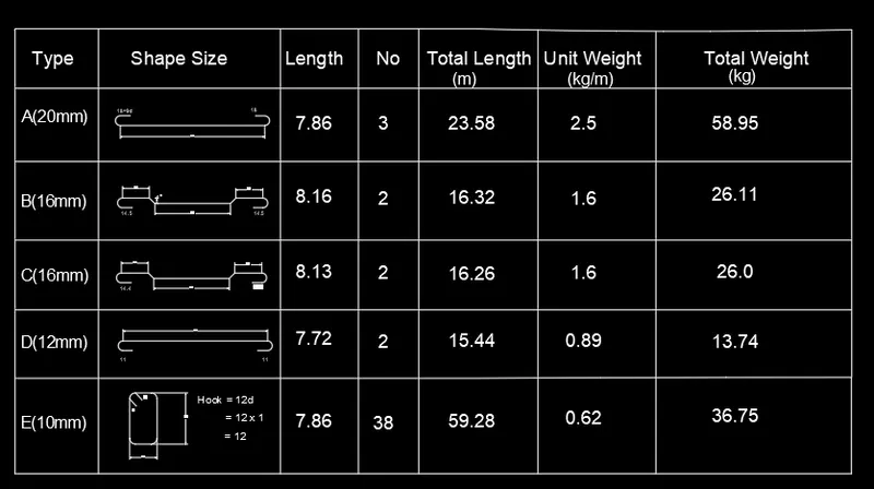
iv) Command Insert - Insert the blocks which we have created in respective type .
v) Complete the table by entering the value .
vi) Change the layers of the table by giving command LA
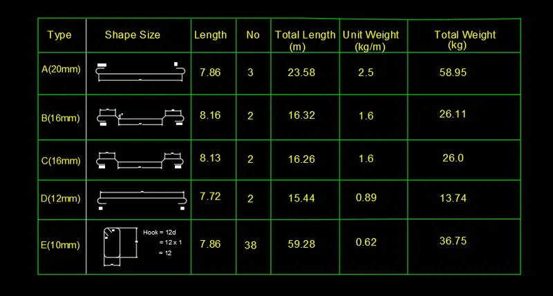
Results - The Bar Bending Schedule is drawn and Each shape is created as block .