Creating Architectural and Structural model with 3D rendering using REVIT
Solution.1)
Aim: To select any one of the structures for designing out of the following:
- Multi-Unit Residential Apartment
- Office Building
- School
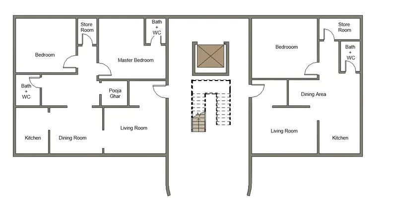
Result: From the given options, I choose a Multi-Unit Residential Apartment with the floor plan shown below.
Solution.2)
Aim: To assume and select a reasonable geographic and location details for our project modelling. Also, to list down the modelling requirements from NBC.
Procedure:
- Open a new Architectural Template in Revit.
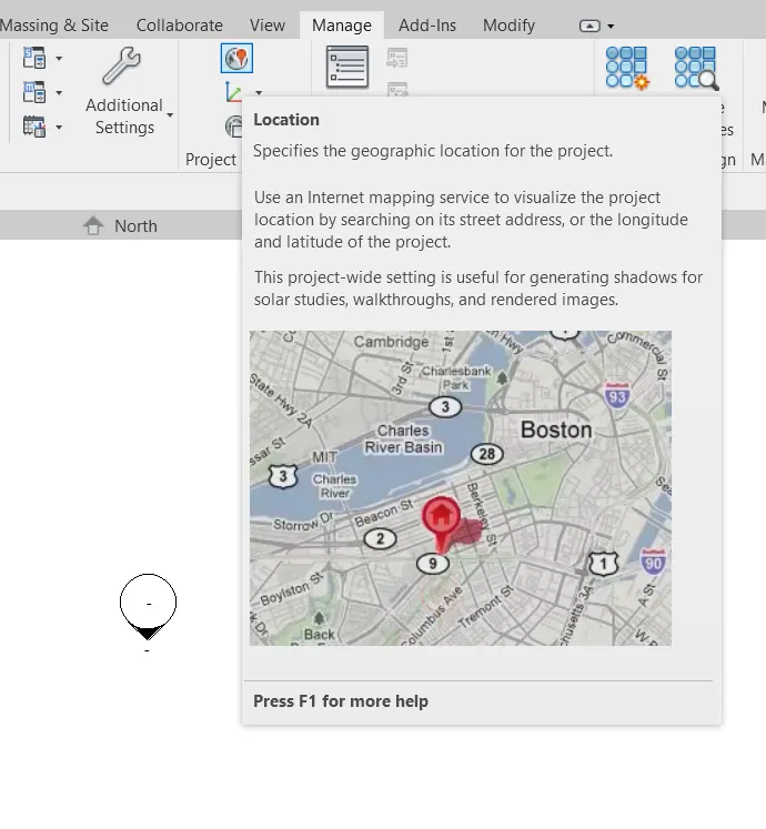
- Go to Manage Tab, select Location option from Project Location Section as shown below.
- Select the location as per your desired location as shown below.
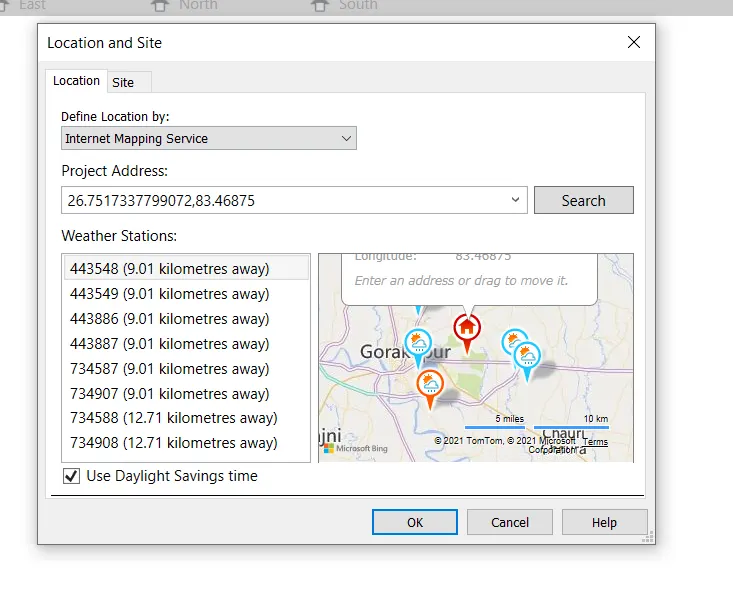
- Click OK to set the desired location.
Below are the major modelling requirements as per National Building Code:
- An exit must be provided in every building, so as to permit the safe escape of residents in times of fire or earthquakes, etc.
- The main staircase and fire escape staircase must be continuous from the ground floor to the terrace level.
- According to the NBC, a dedicated refuge area should be on every seventh floor or after the first 24m in a high rise building structure.
- No chutes to be used in buildings above 15 m.
- One of the walls of Bathrooms should have an opening to the open air. Minimum ventilation or window space should be provided measuring up to 0.37 sq.m.
- A bathroom must always be over another bathroom or washing place or the terrace space and not over another room.
- Every room, habited by people, should open into an exterior or interior open space or verandah.
- Open spaces should be counted in the FAR, as per the master plan.
- Every interior or exterior or air space should be maintained for the benefit of such building exclusively and shall be entirely within the owner's own premises.
- Nothing that is combustible can be used for decoration or panelling of the staircase.
Solution. 3)
Aim: Using the structural model, include the following components based on the type of structure selected
a. Foundation – Isolated / Wall/Matt Foundation
b. Columns
c. Beams Connected to Columns
d. Roof Framing/ Truss
e. Floor / Decks
f. Floor Openings for Elevators and Stairs
Procedure:
- Open a new Structural Template file.
- Go to Structural Tab, select Grid Option and draw a horizontal and vertical grid.
- Now go to the Manage tab and use the Manage link option to import Architectural File.
- Go to collaborate option and select the Copy/Monitor option to copy the imported grids from Architectural File.
- If the grids are not matched properly, use Relocate project option under Manage Tab, to match the grid system.
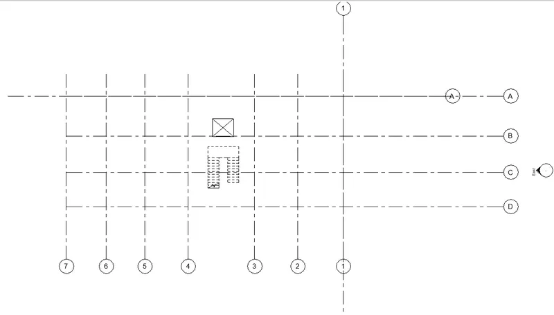
- Now the grids are matched ready for designing a structural plan as shown in the below figure.
- Go to Structure Tab, and Select Isolated Footing.
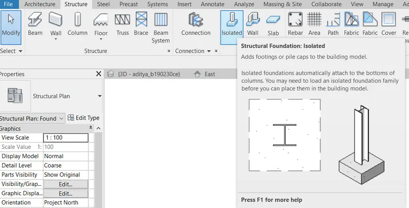
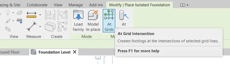
- Now select the "at grids" option, to place the Isolated foundation at the Foundation level by opening the Foundation Site plan.
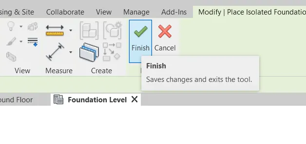
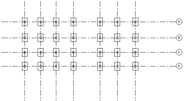
- Select the grids and click on the Finish Option.
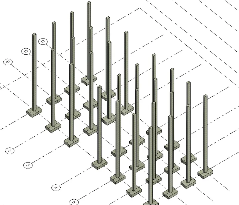
- Now, repeat the same steps for adding columns at Foundation Level.
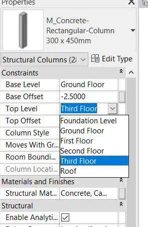
- After that go to the properties tab after selecting columns and set the top constraints to Third Floor Level as shown in the figure.
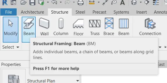
- Now, go to Structure Tab and Select Beam Option.
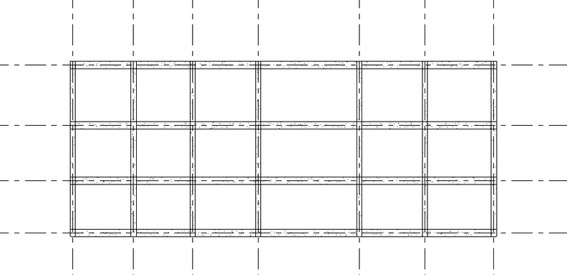
- Place the beams to make a Grider System for each floor, by choosing the suitable beam size.We have used two sizes of beams:
- Beam A (450mm X 600mm)
- Beam B (300mm X 600mm)
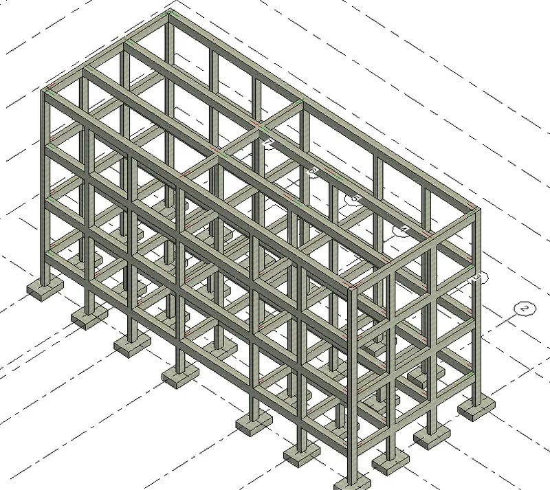
- After placing the beam the Structural 3D View will look like as shown in the below figure.
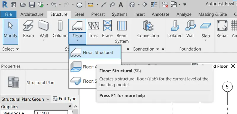
- Now, again go to Floor Option in Structure Tab and draw the outline for the floor at all the levels i.e., Ground Floor, First Floor, Second Floor, Third Floor.
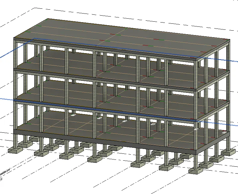
- After drawing the floor on each level, our structure will look like as shown in the below figure.
- Now, to add Shaft for Stairs Opening, Open the Structural File and Go to Structure Tab and Select Shaft Option. Draw the area over the stairs over which we want the shaft opening and Click on the Finish Option.
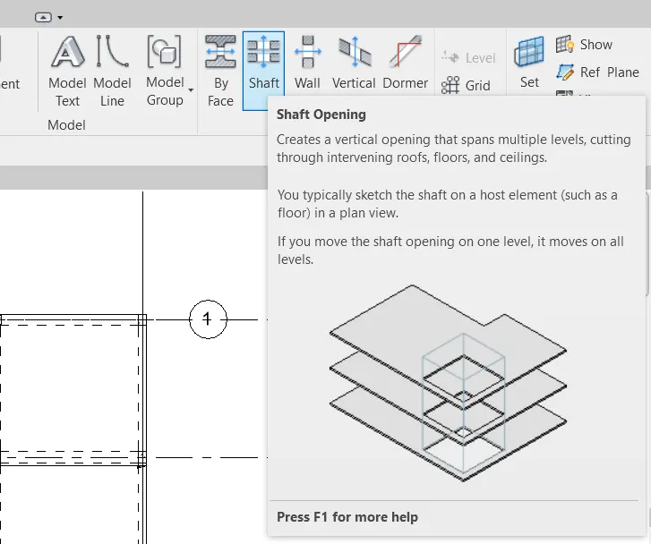
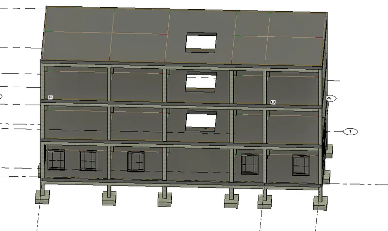
- The shaft has been created for Stairs.
- In Architectural File, the Structure will look like as shown in the figure.
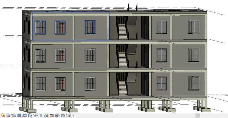
- Now, go to Architectural File, and add walls at the third floor to make headroom for stairs and add roof option to add roof in Architecture Tab.
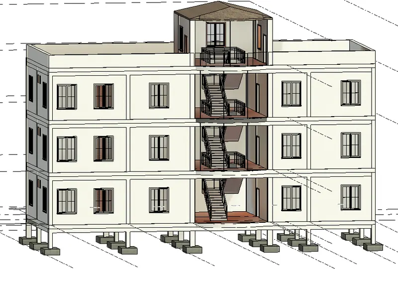
- The final structure will look like as shown in below figure.
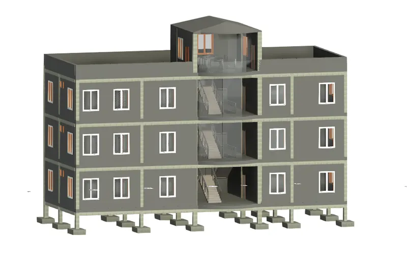
Result: All the desired components have been added.
Solution.4)
Aim: Using the architectural model, include the following components based on the type of structure selected
a. Wall Layout with appropriate material and finishing
b. Exterior façade with fancy finish
c. Interior partition walls to size rooms
d. Components to add details to a room ( Desk, Chair, Lighting, Plumbing fixtures)
e. Add components such as stairs Elevators
f. Have at least one side of the building with curtain walls and glass panels
g. Include interior and exterior lighting fixtures
h. Place proper topographic components from outside ( Trees, Parking, Plants) to add details to the model
Procedure:
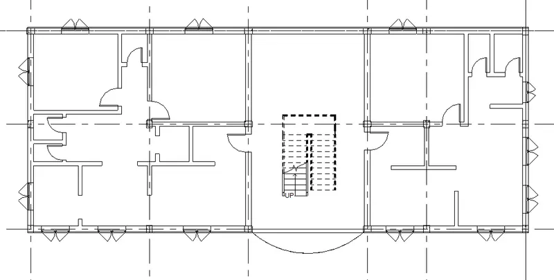
- Open the Architectural File, and use walls, door and windows option to add wall partition and add doors and windows in building.
- Below is the ground floor plan with doors and windows.
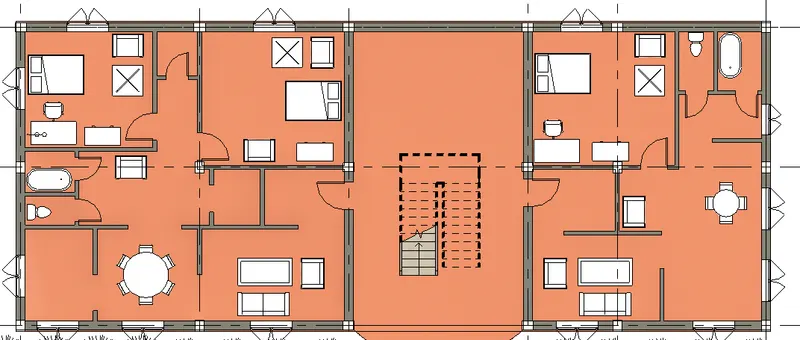
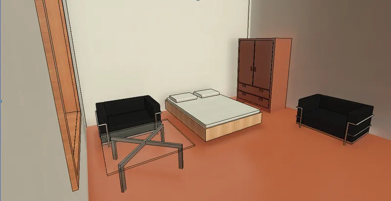
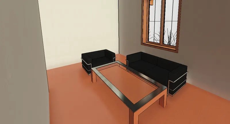
- Now, go to Architecture tab, and place components to room like Beds, Sofas, Table, Chairs, etc.
- Also, place lighting and other important components to drawing.
- After adding all the components our plan will look like as shown in below figure.
- Use the types of wall and different materials to give finishing to the wall using property tab.
- Finally after selecting proper material and paints to give a good facade look, our building will look like as shown in below figure.
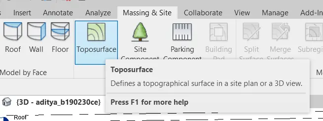
- Now to add topography, go to Massing and Site Tab and Select Toposurface Option.
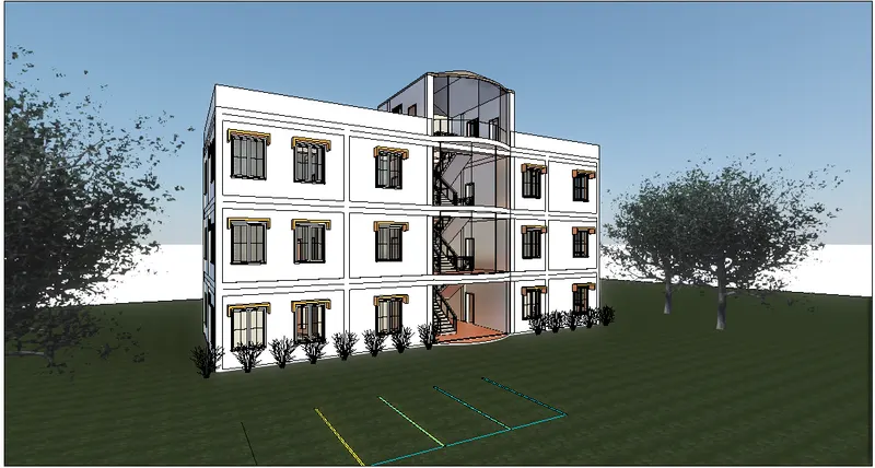
- Add components like Plants, Trees, etc to topography using the Site Component Option.
- After adding all these our Building will look like it as shown in the below figure.
Solution.5)
Aim: To Provide a set of drawings in an architectural and structural model to list the following details with categories and appropriate sheet templates included
a. Floor Plans with Annotations
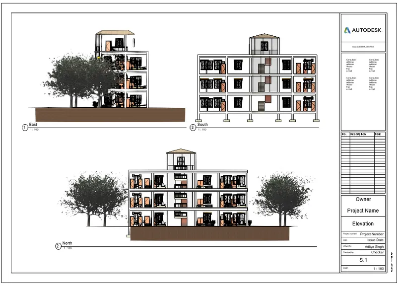
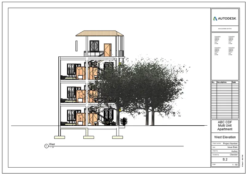
b. Elevations
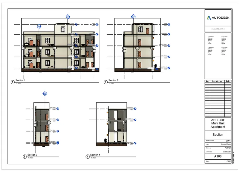
c. Sections
Procedure:
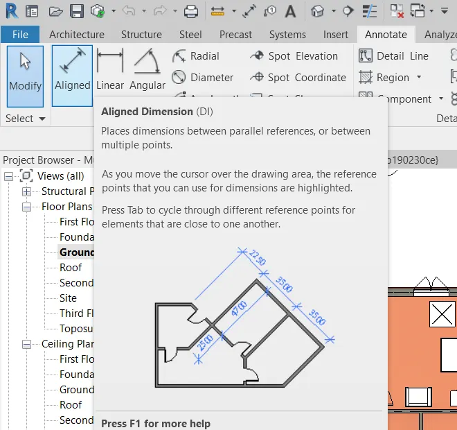
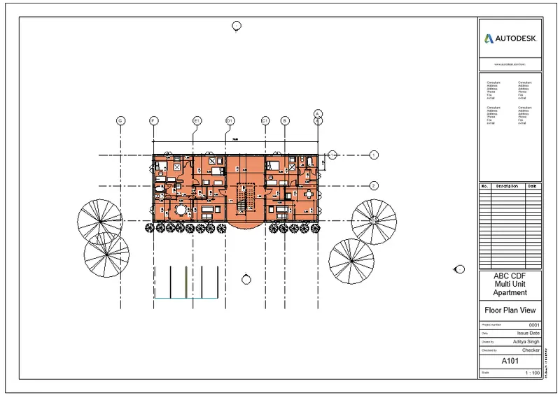
- Open Architectural File, go to annotate tab and select aligned to give proper dimensioning to our drawings.
- Now, go to View tab and Select Sheet Option to add sheets. Now Open the Project browser and drag the floor plans to Sheet.
- The final sheet of floor plan will look like as shown below.
- Do the same procedure to add Elevation Views and Section Views.
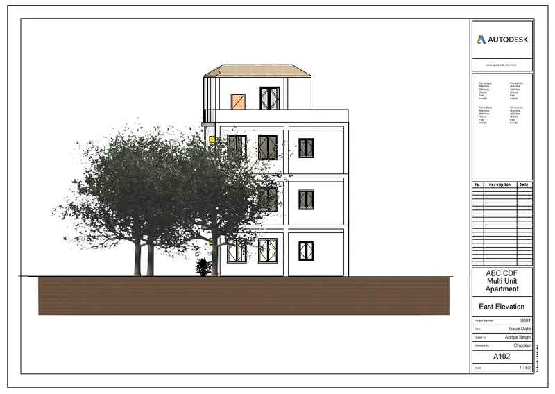
East Elevation
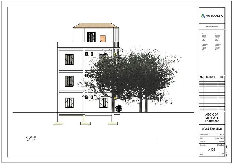
West Elevation
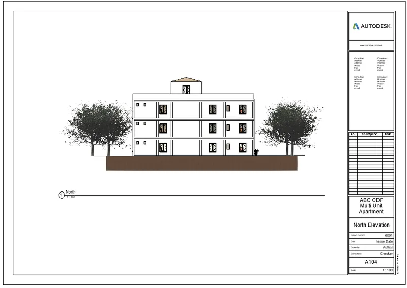
North Elevation
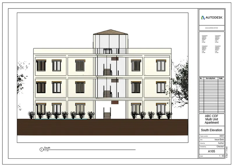
South Elevation
- Now create the section view and add it to sheets
- Now open the Structural File and go to View Tab and select the Sheet option.
Result: All the desired drawings have been added to drawing sheets.
Solution.6)
Aim: Using the Rendering settings, Render images of the 3D model produced and include the rendered images in the drawing sheets
a. Rendering from interior rooms
b. Rendering from out showing topographic features
c. Rendering through structural framing
Procedure:
- Open the Architectural File, Go to View, Create a Camera Specific View.
- Render the view and add to sheets as done before for adding drawings to sheets.
- The Rendered image of exterior and interior rendered view are shown in below.
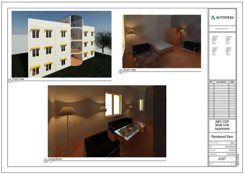
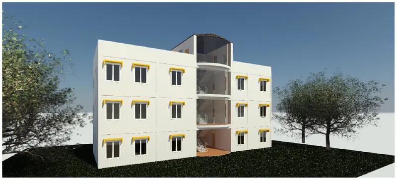
- Now, open the Structural File, and do the same to create camera view, render and add to sheet.
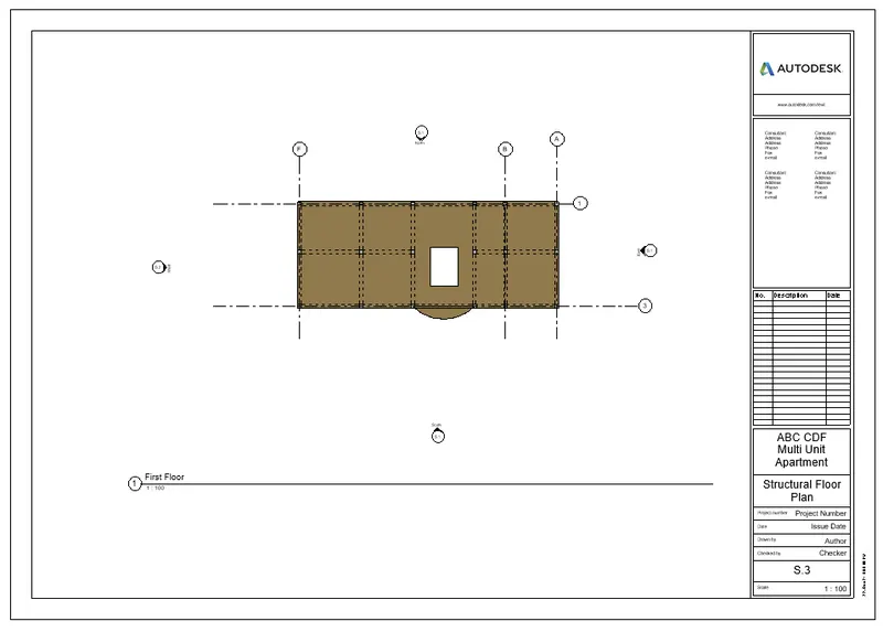
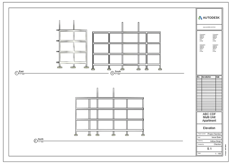
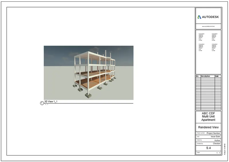
Result: All the rendered views have been added to the sheets.
Solution.7)
Aim: To Print the set of drawing sheets created and submit the drawings from the architecture and structure model
Procedure:
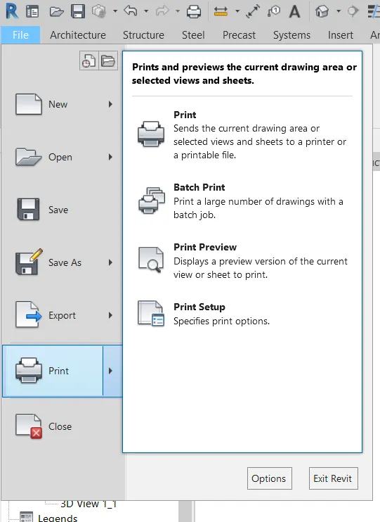
- A dialogue box will appear, select the "Selected Views option" and then select the views, sheets you want to print.
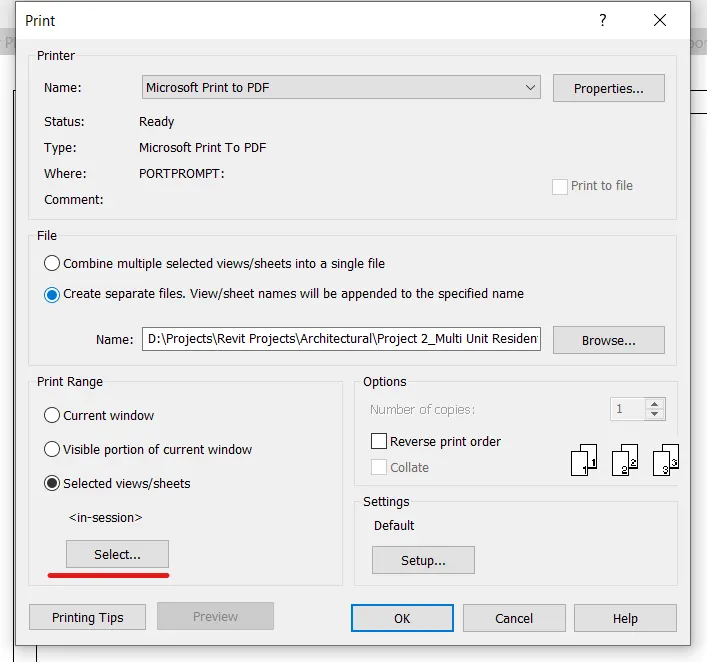
- Then click on the OK button.
- Do the same with the Architectural files.
Result: All the sheets have been printed (we have saved them as pdf).