Creating Architectural and Structural model with 3D rendering using REVIT
1.ans.:) I am going to design a Multi-Unit Residential Apartment.
2.ans.:) Aim:- Assume reasonable assumptions for geographic and location details for your project modeling. Based on assumptions and type of structure selected identify the modeling requirements from NBC.
- This apartment is being modelled for plain terrain and is located at mid of a city.
- According to NBC it falls under GROUP-A residential buildings, sub division A-5.
- Overall height of apartmemt will be 40'.
- Width of the road passing the apartment will be 50'.
- Habitat height of rooms is 10'.
- Thickness of wall is considered to be of 8".
3.ans.:) Aim:- Using the structural model, including the structural components based on the type of structure for design.
Tools used:- Revit, Structure Tab, Various options such as Foundation, Beams, Roof framing, Truss, Floor, Shaft openings etc.
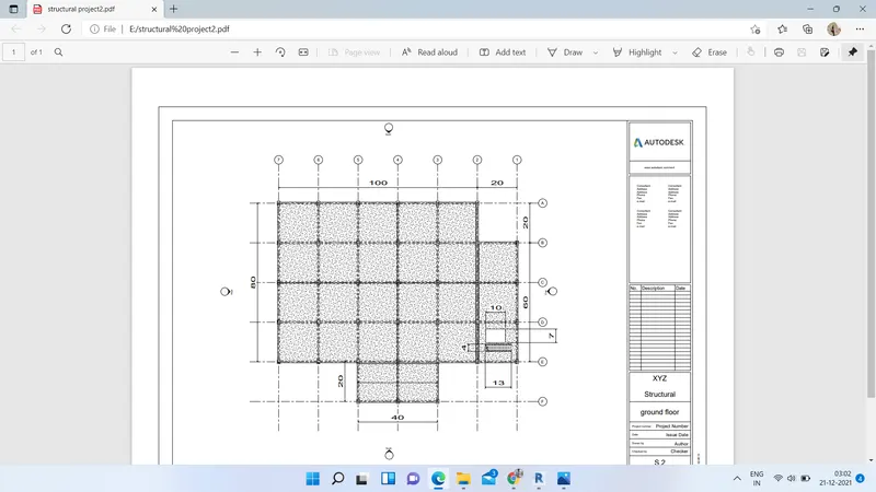
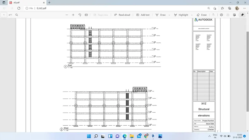
The structural plan drawings show the foundation, floor, and roof plan of the building. These plans provide information like size and location of the structural elements present in the respective plans. Elevations show the exterior walls of a building or structure. It is a framework to guide the development or redevelopment of an area by defining the future development and land use patterns, areas of open space, the layout and nature of infrastructure (including transportation links), and other key features.
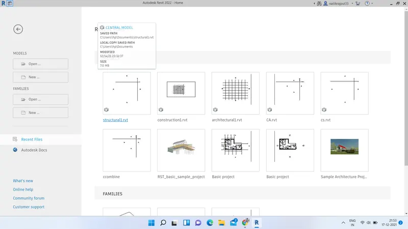
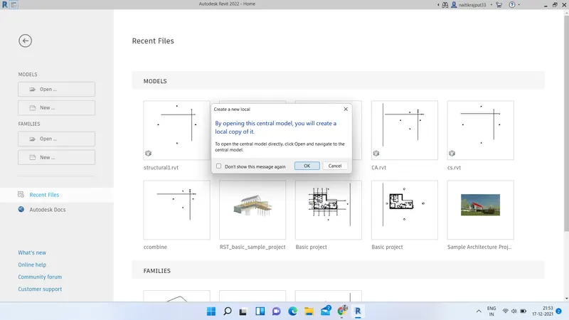
- Launch the Revit and open the Structural file created in previous project. As that was a central model we will create a local copy of that.
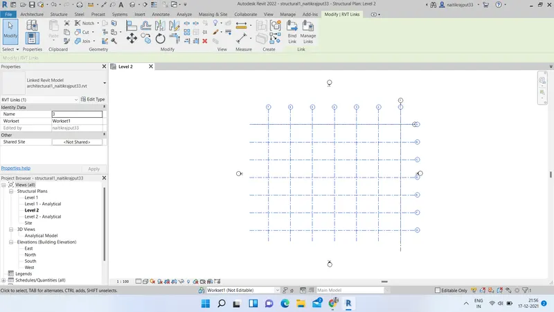
- Also Open local copy of central architectural file created and link structural file in it using shared coordinates, if not linked already.
- After linking again open the structural file and draw the horizontal and vertical grids. Also add different levels for our project and rename it.
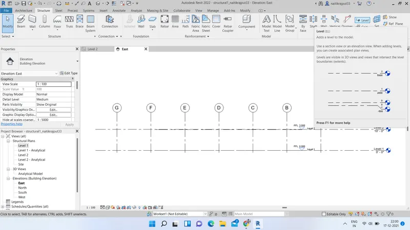
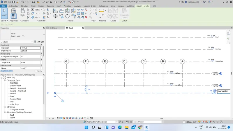
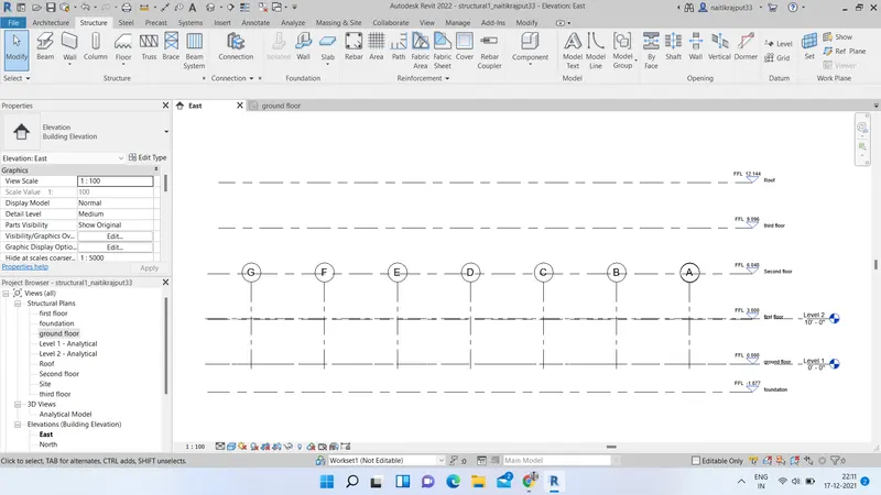
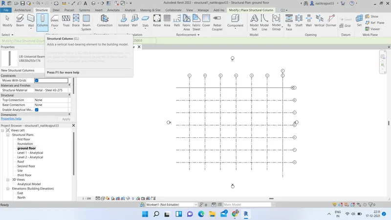
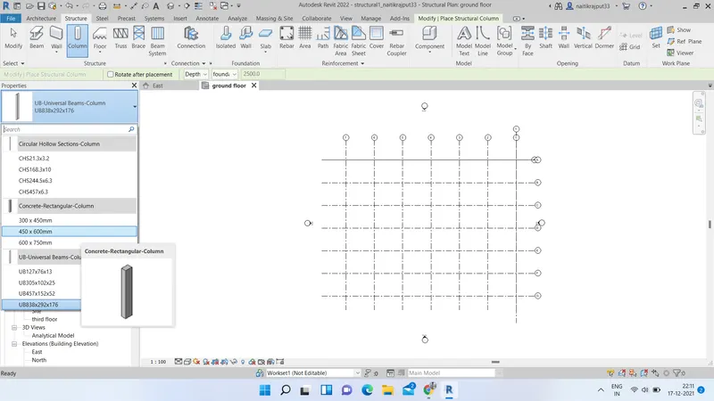
- Now go to Column option under structure tab and select a desired column. In modify tab select grid intersection and insert the columns at grid intersections at ground floor level.
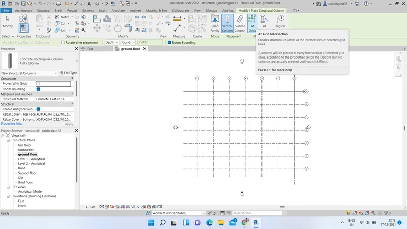
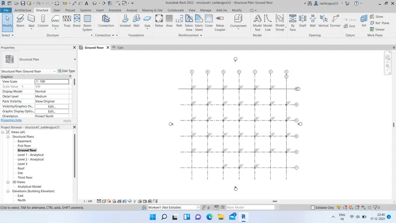
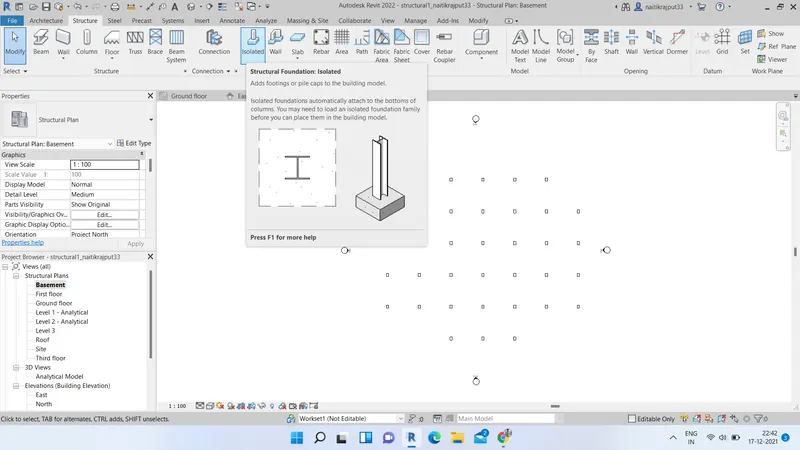
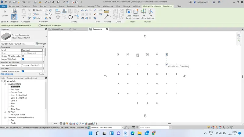
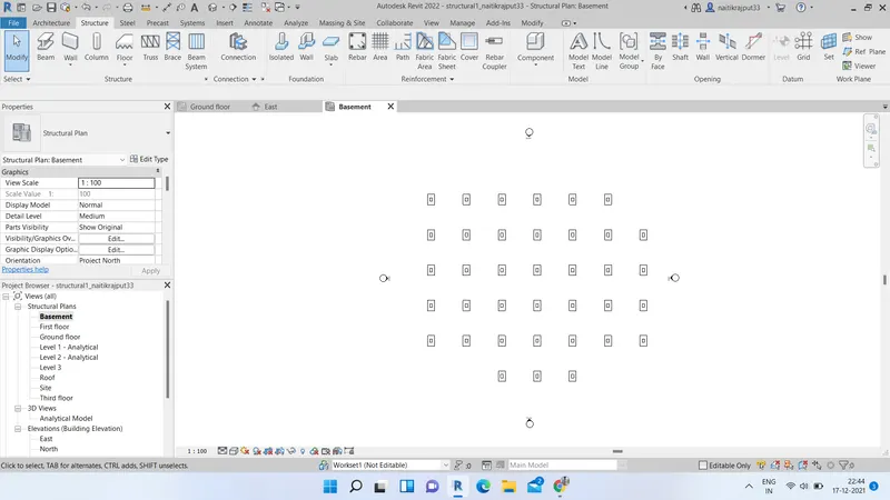
- Now go to basement level. Select isolated foundation from structure tab and insert it at columns position.
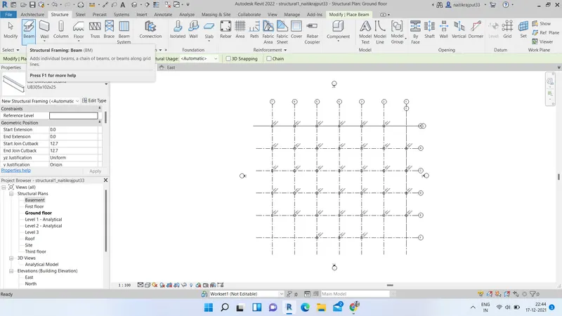
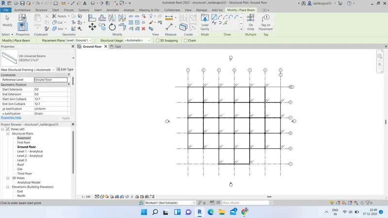
- Now select Beam option from structure tab and select desired beam type. Using pick lines coonect the columns to place beams.
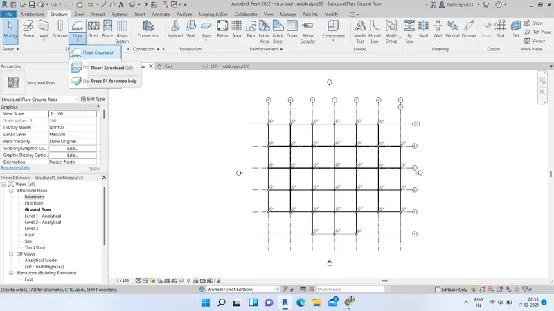
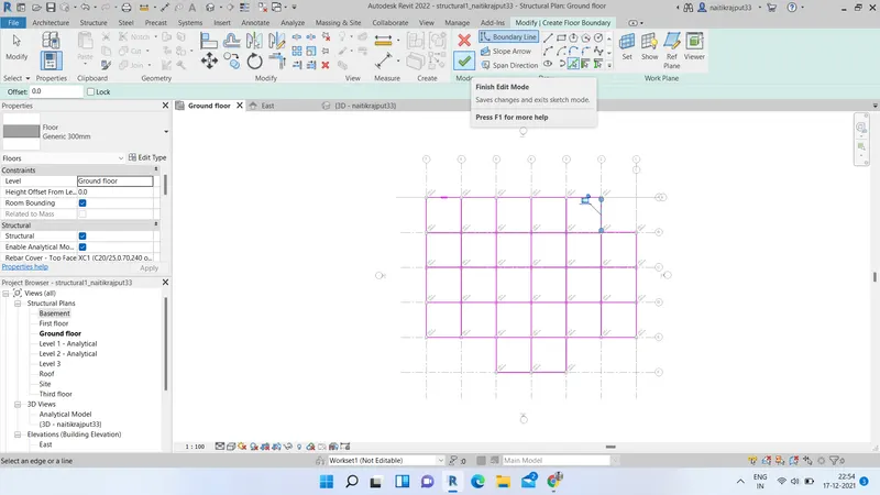
- Select floor option from structure tab and draw floor boundary using pick lines or lines tool. click on finish after completion.
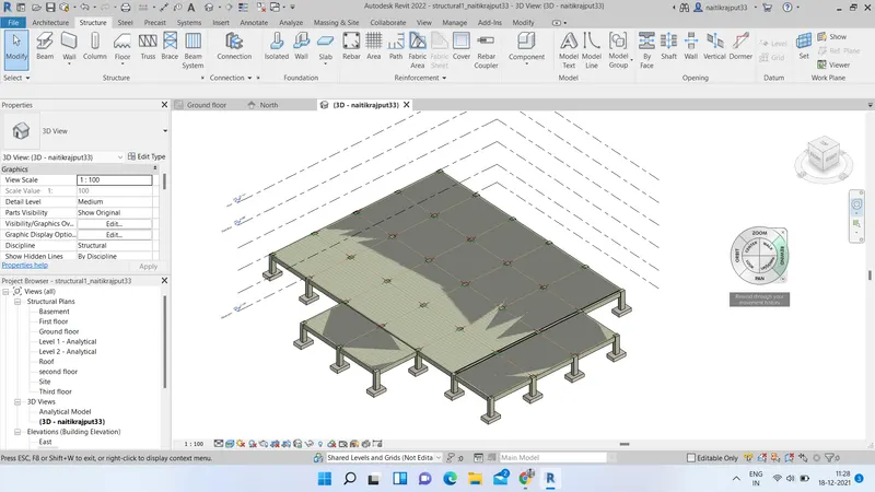
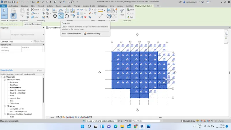
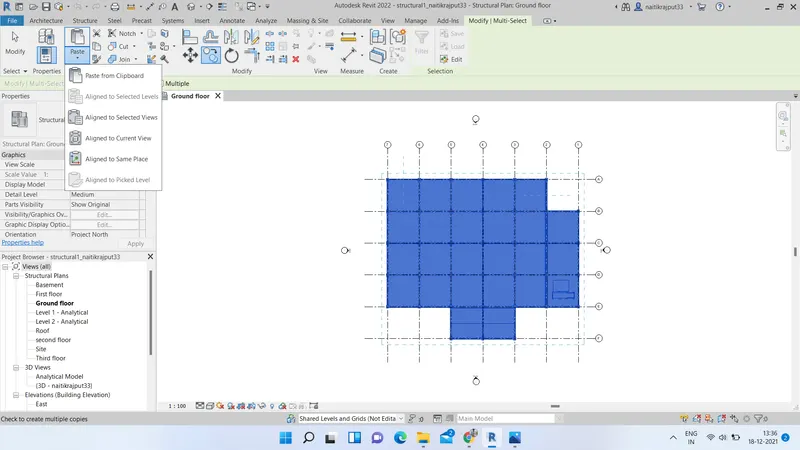
- Now select all elements except footings and Copy from clipboard. Using Paste option paste it to clipboard aligned to selected levels. Select the levels and paste.
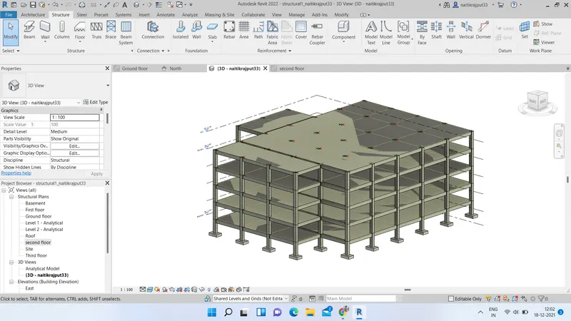
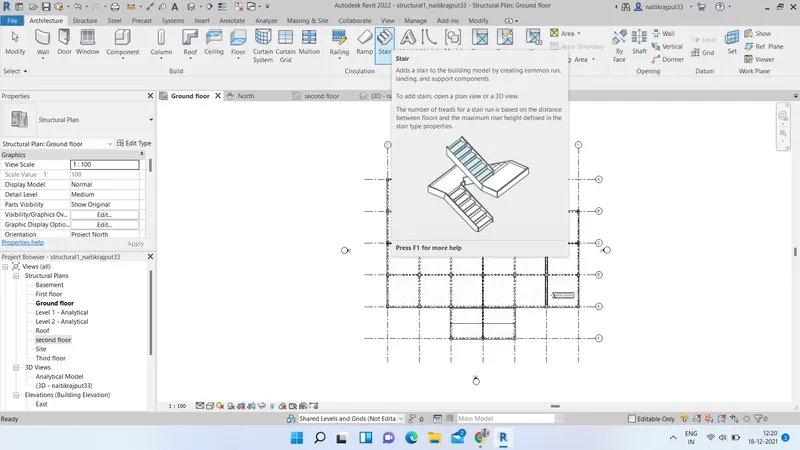
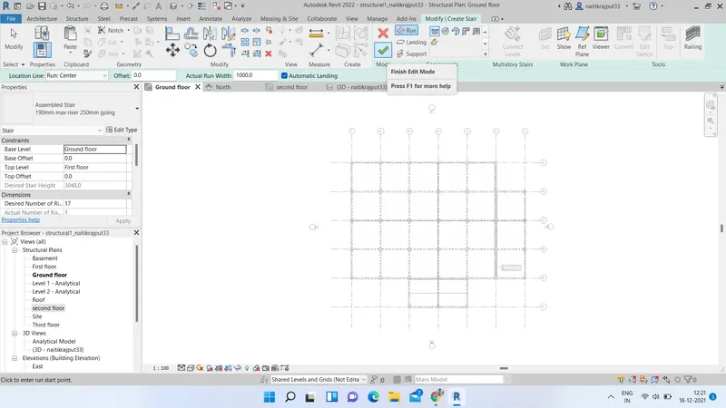
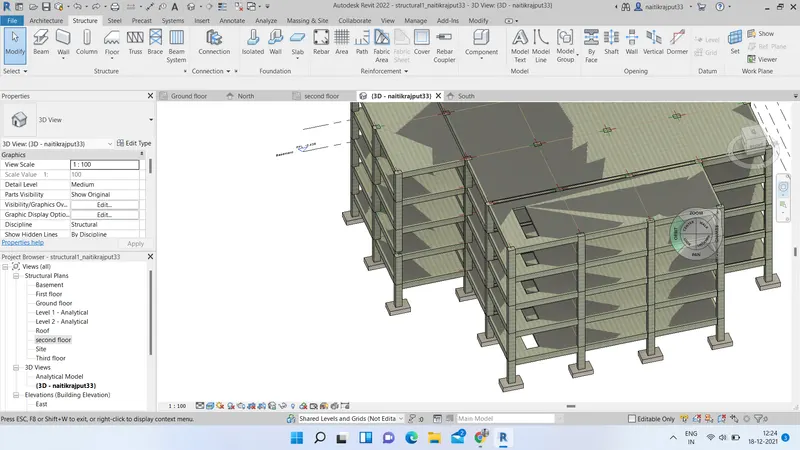
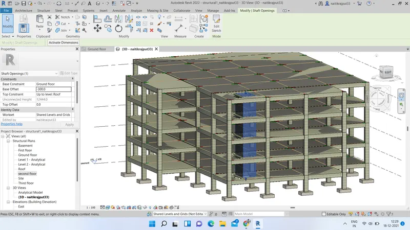
- Go to architecture tab and select stairs. Click on run and draw the stair at ground floor level. Select stair and connect it to desired levels. Now go to shaft option under structure tab and create openings for elevator and stairs. Fix the top and base constraints for openings. Create separate openings for stairs and elevators.
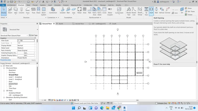
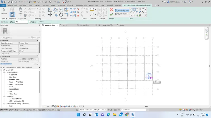
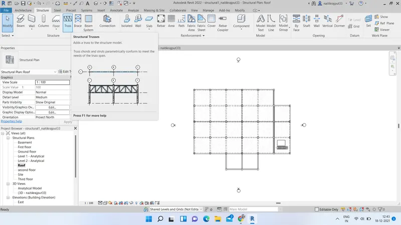
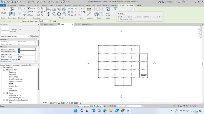
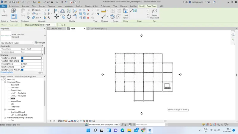
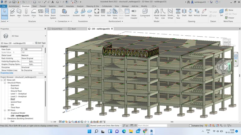
- If you want to model Truss select truss option from structure tab and place it at Roof level. Using pick line tool model the truss element.
Results:
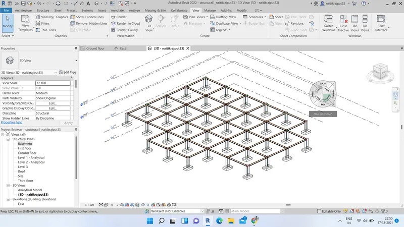
We have succesfully modelled Foundation footings, columns, beams to support the column, Floors and truss elements in structural model. Shaft openings for stairs and elevators are also provided.
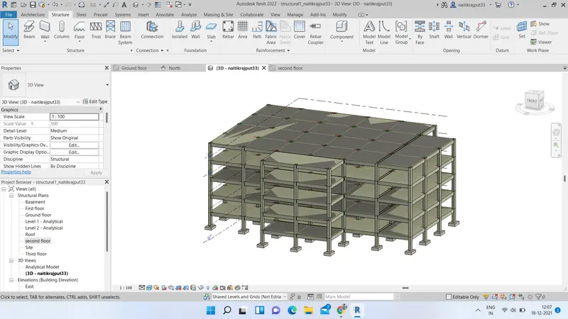
4.ans.:) Aim:- Using the architectural model, including various components based on the type of structure selected. Proper designing of Architectural model with all interior and exterior components.
Tools used:- Revit, Architecture tab and various options such as wall, different families, site features etc.
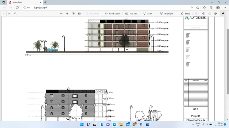
Architectural plans include working drawings, schedules, and other sheets shown in the list below. Many architectural plan sheets are horizontal (section) views of the building. The most common plan sheets include floor plans, foundation plans, and roof plans.
As we have linked our structural model into architectural one, all the changes we made into structural will be available in architectural too. After modelling structural components we will save and exit from structural model.
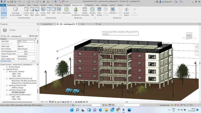
- Open the architectural model saved. We can visualise our structural components modelled. Go to architecture tab and select stairs. Click on run and draw the stair at ground floor level. Select stair and connect it to desired levels. Now, we will add exterior walls in model. For this go to Architecture tab-->>Walls. Select the desired exterior wall and edit it using edit types option in property browser if needed. Fix all constraints and Using Lines tool place the wall accordingly. Select wall type as desired and place.
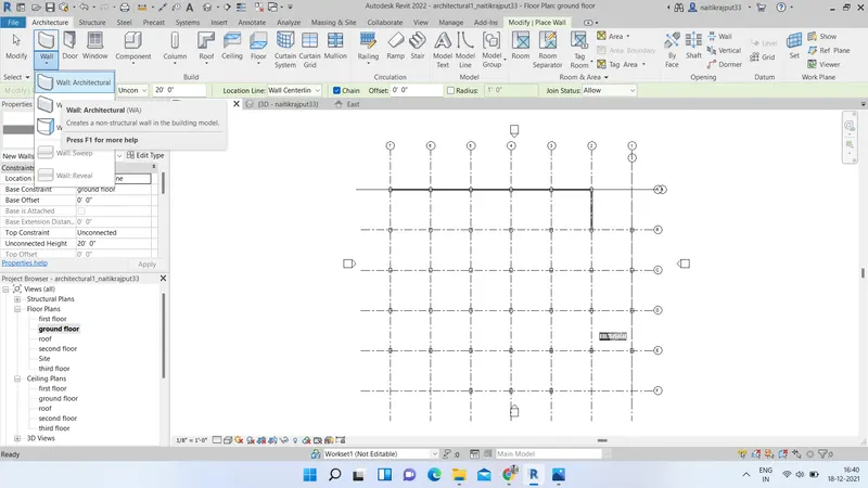
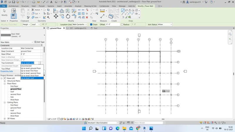
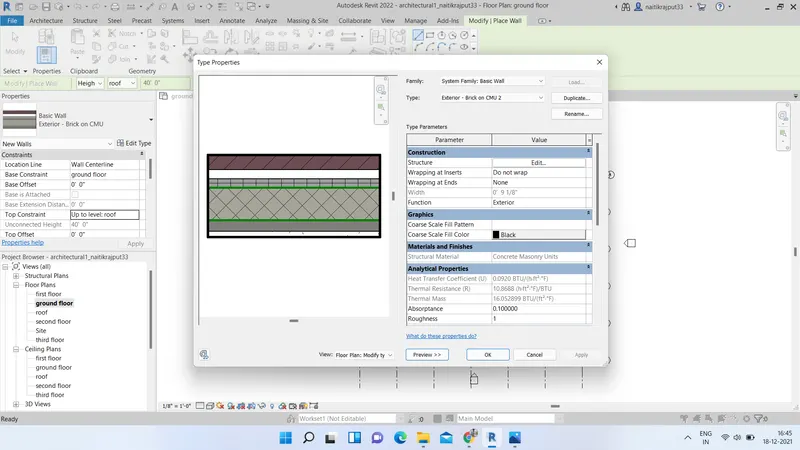
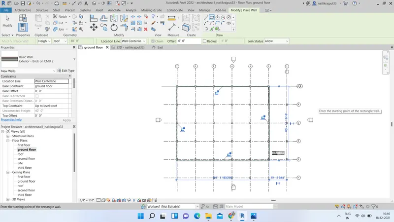
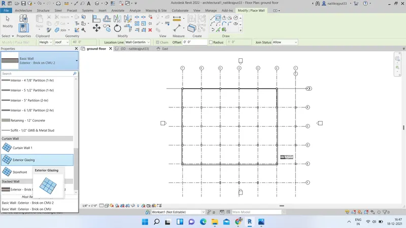
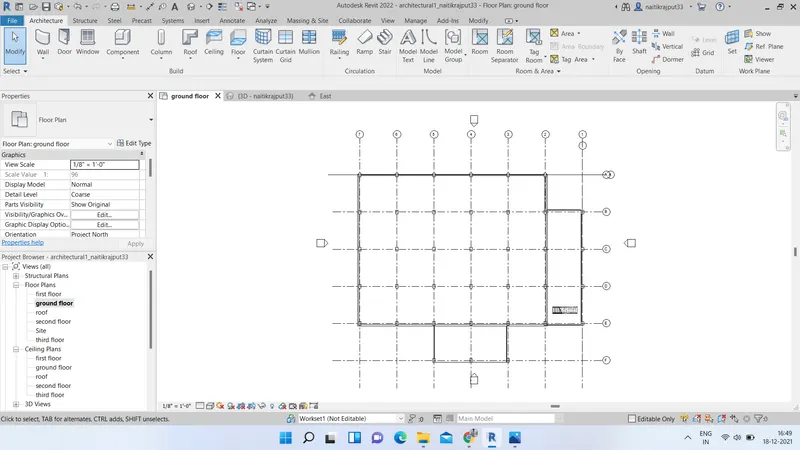
- Now, we will add interior walls according to flat partitions. Go to architecture tab-->>walls. Select desired wall type and place it accordingly using lines tool.
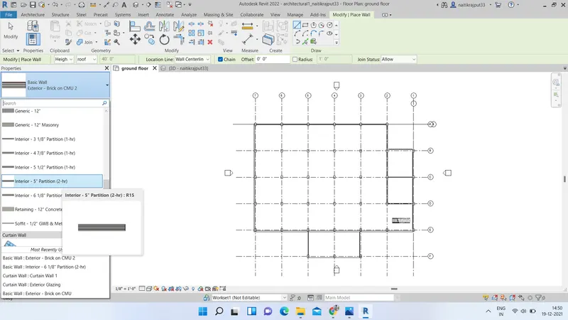
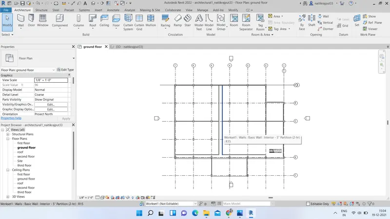
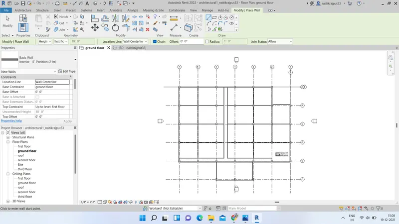
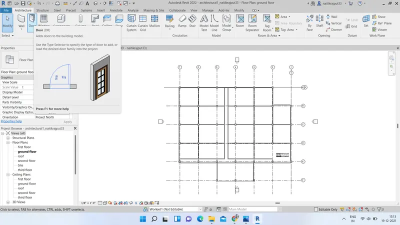
- Now, place Doors and windows using windows and doors option from Architecture tab at desired locations.
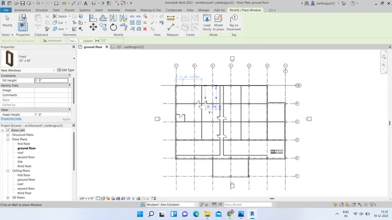
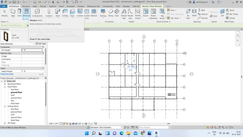
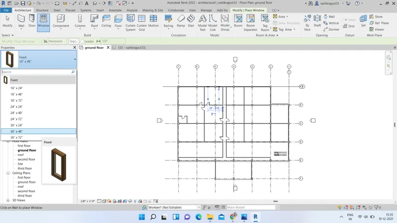
- Place different components in rooms according to room type and need. Insert from families aur load different families as per need and place.
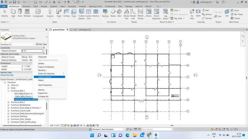
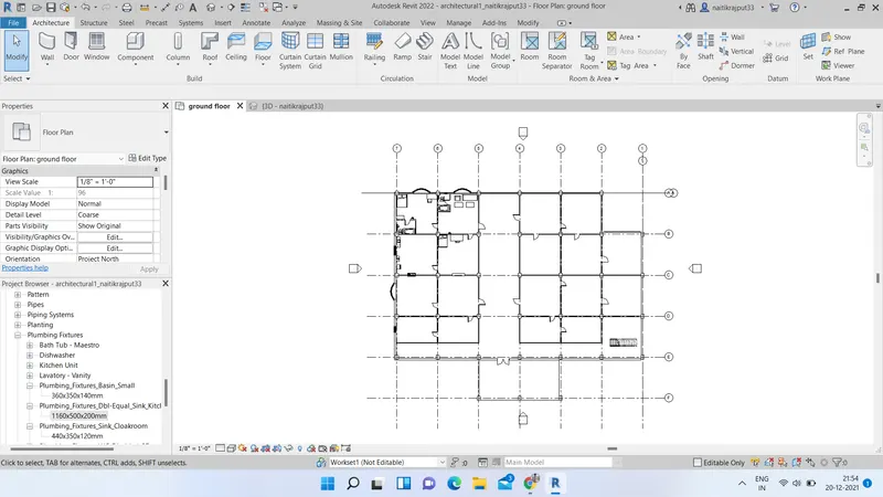
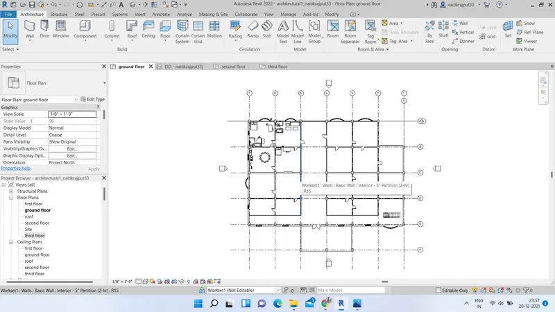
- Similarly add details to all rooms and select sll instances from ground floor. Copy from clipboard and align paste it with aligning to selected levels.
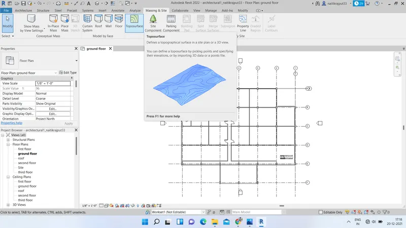
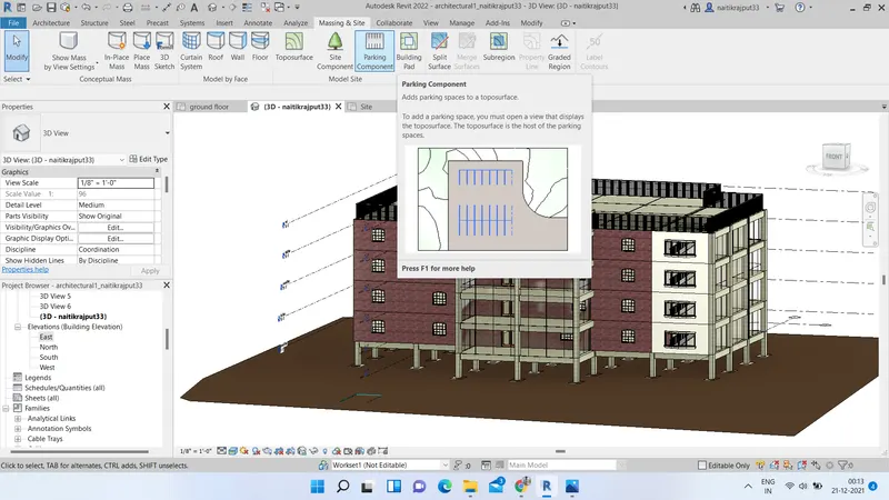
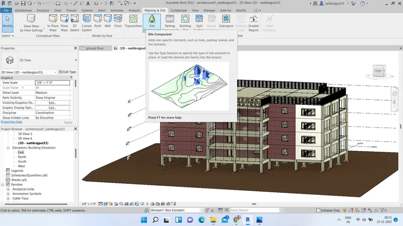
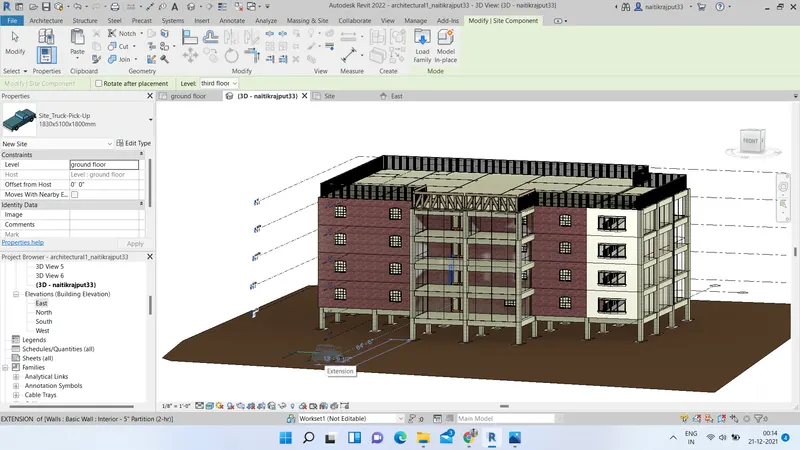
- Now Select site option from architecture tab and model different site components like trees,parkings,topography etc.
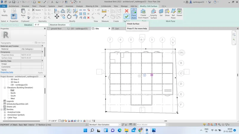
Results:
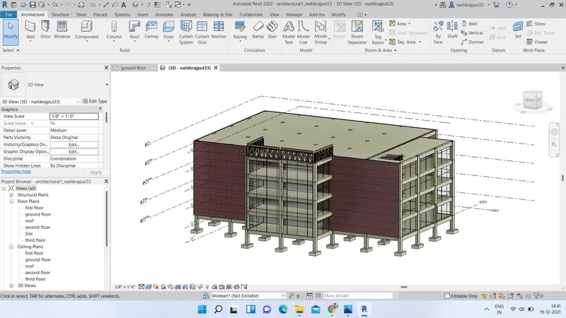
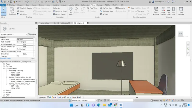
We have modelled architectural components as per need. We can view results by switching to various views and elevations as follows.
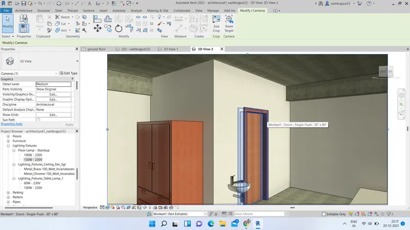
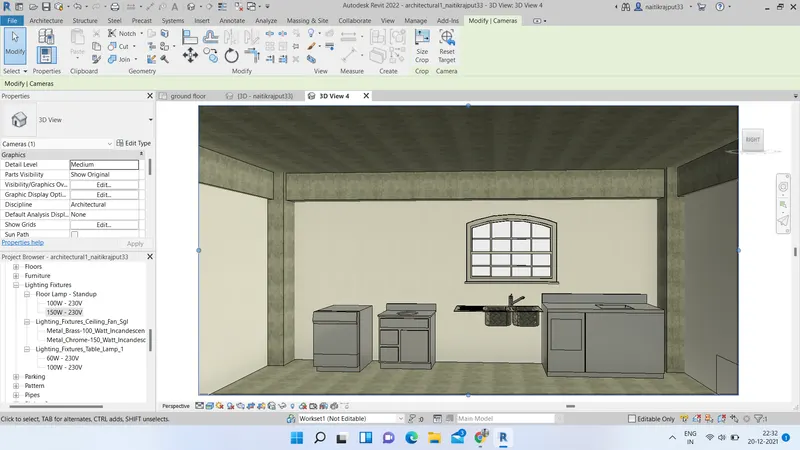
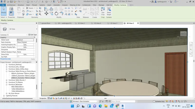
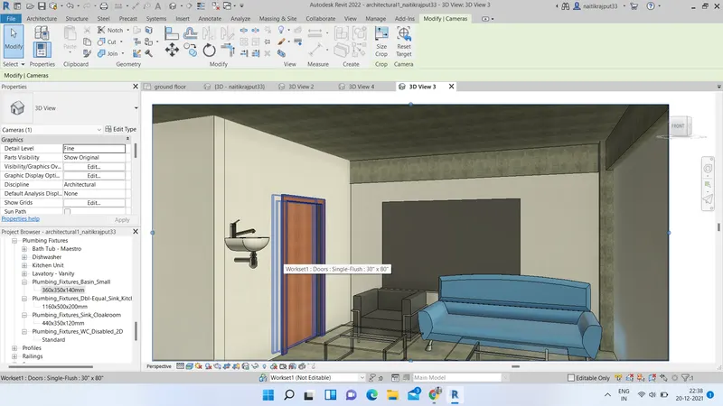
5.ans.:-) Aim:- Providing a set of drawings from architectural and structural model to list the desired details with categories and appropriate sheet templates.
Tools used:- Revit project, View tab, Different Views, Sheets option etc.
A construction document set (also called a drawing set or a sheet set) consists of several sheets. In Revit, we create a sheet view for each sheet in the construction document set. We can then place multiple drawings or schedules on each sheet view.
In project browser all views are visible. We will insert these views one by one in sheets.
- Go to View tab and select sheet option. Load the sheet and click OK.
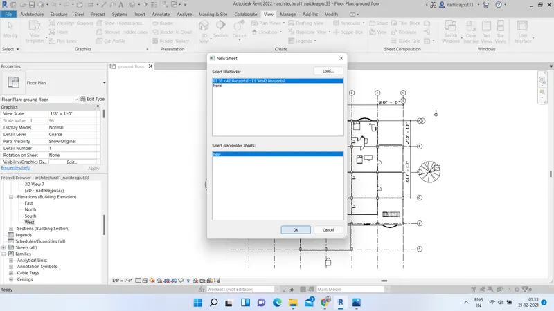
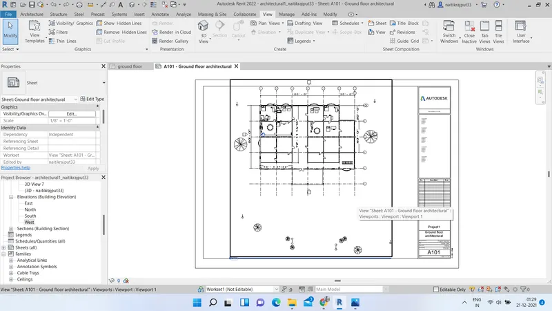
- Edit Sheet information. Now select View option View tab and insert the Ground floor plan at first in sheet. Give name A101 to sheet.
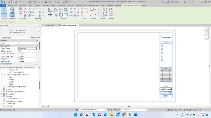
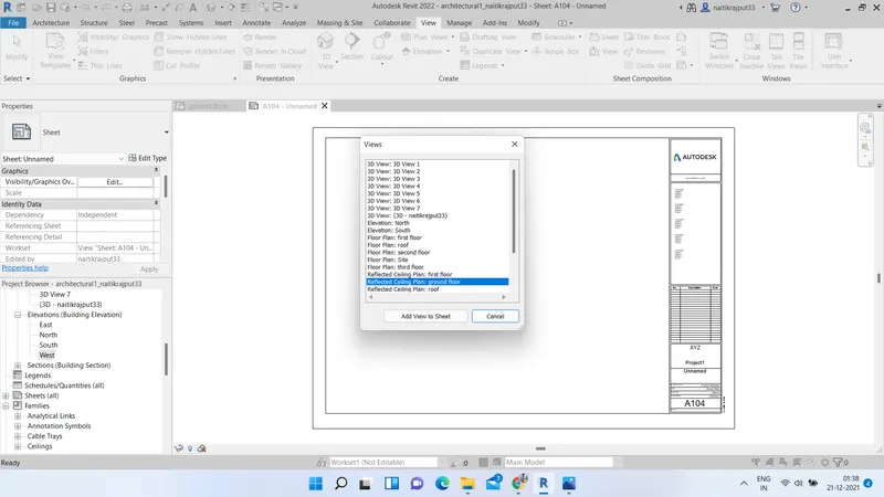
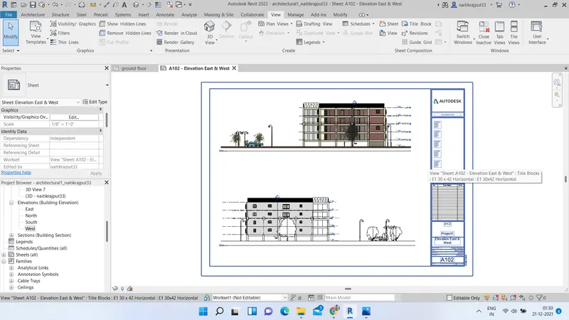
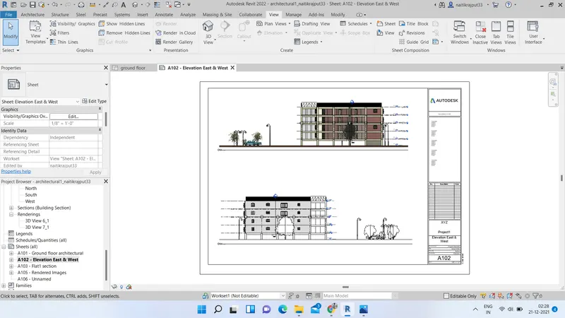
- Now add elevations in sheet with Name A102.
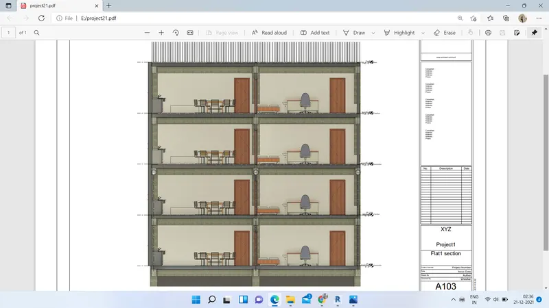
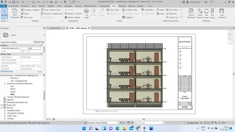
- Next add section view with name A103.
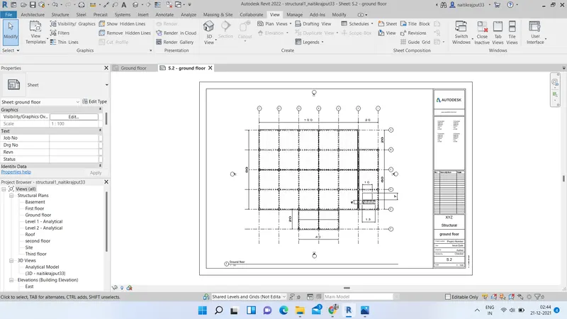
Similarly add all views in like elevation plans, structural plans with desired names from structural model too.
Results:-
Sheets obtained after adding all elements:
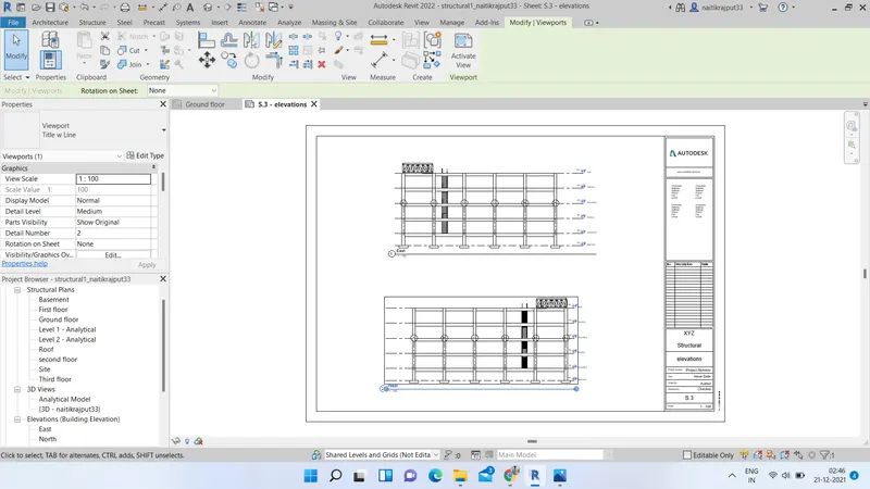
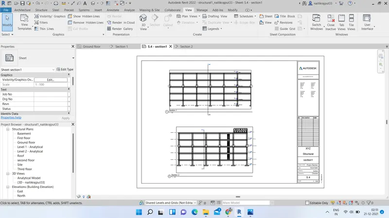
6.ans.:) Aim:- Using the Rendering settings, Rendering the images of the 3D model produced and including the rendered images to the drawing sheets.
Tools used:- Revit, Render settings, View tab, sheets etc.
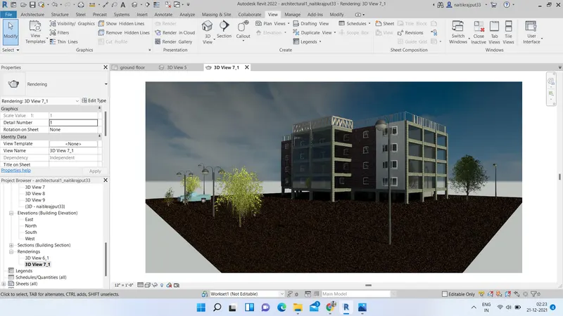
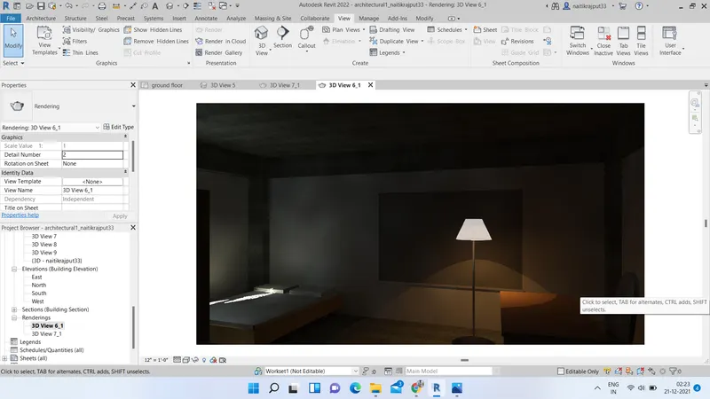
We can render 3D views from a model. We can place rendered images on sheets to present designs. The rendering engine uses complicated algorithms to produce a photorealistic image from a 3D view of a building model.
For Rendering atfirst create some view by using camera option from view tab and 3D view option.
After views are created:-
- Go to bottom part of screen. Select show rendering dialog option from there.
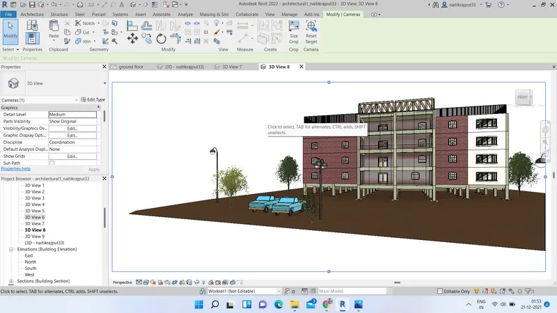
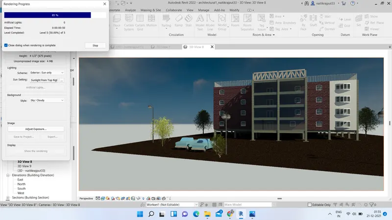
- Set the features as desired and click on render. Wait till Rendering is complete.
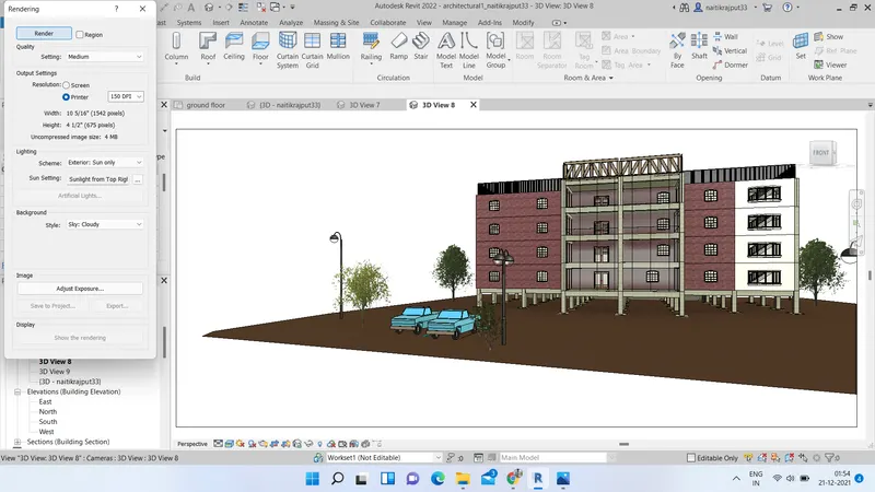
- Click on save to project option for saving the rendered image to project.
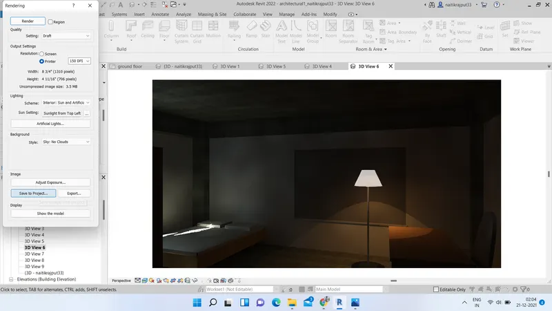
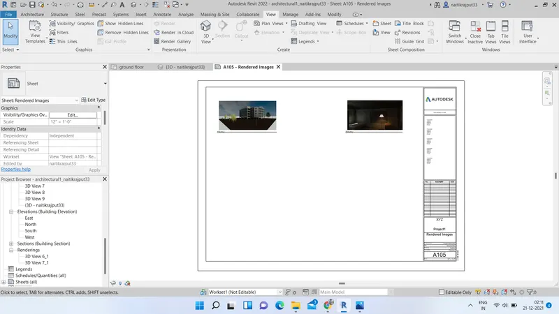
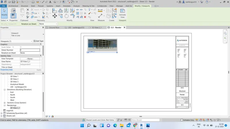
- Now using view tab and sheets option, insert the rendered images into sheets with proper name.
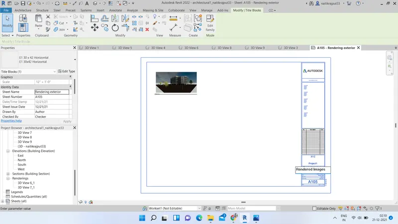
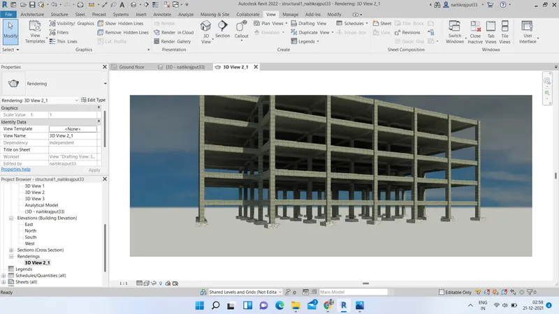
Similarly render for structural framings in structural model.
Results:-
7.ans.:) Aim:- Printing of set of drawings from sheets created.
Tools used:- Revit, Project browser, Views, Sheets etc.
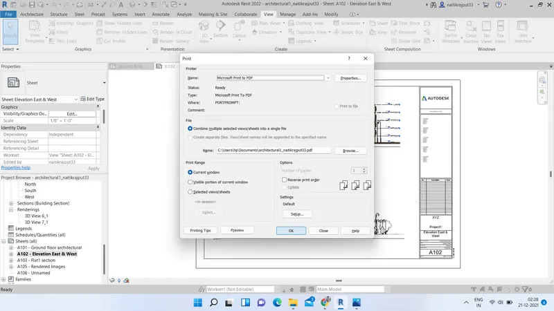
Go to sheets created and press ctrl+p. Print dialog box will appear.
Change the settings as required and press OK.
Results:
Structural and architectural drawings are obtained as follows:-