Creating Levels, Grids, Layout and model elements for a residential unit using REVIT
BIM is Building Information Modeling. It is an integrated workflow built on coordinated, reliable information about a project from design through construction and into operation.t
It is used for creating and managing data during the design, construction, and operations process. BIM integrates multi-disciplinary data to create detailed digital representations that are managed in an open cloud platform for real-time collaboration. Using BIM gives you greater visibility, better decision-making, more sustainable options, and cost-savings on AEC projects.
CAD is simply the use of computer systems to assist with design. While BIM tools such as Revit are technically CAD programs, the term "CAD" is used more for drafting programs. In terms of building design, CAD is essentially using a drafting tool, such as AutoCAD, to create lines and arcs to represent a building design. When we select one of the CAD walls on the right, we can see that it is actually just a line. Two lines have been drawn in parallel to represent a wall. Looking in the Properties palette, the only parameter available is the Line Style. However, when we select a BIM wall on the left, we can see that it is an actual wall element. In the Properties palette are several parameters that can be used to define the wall.
Now, we have to explore various options in Revit.
Aim:- To create a basic Project file and explore various options of Revit like inserting a family, creating Levels ,grids and basic 3d modelling.
Tools used:- Revit Software, Various tools of Revit
We have to create a basic Project to understand Levels and grids and start a basic 3d modelling in revit. For this, at first Install Revit on your pc and launch it.
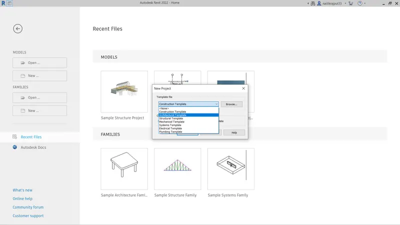
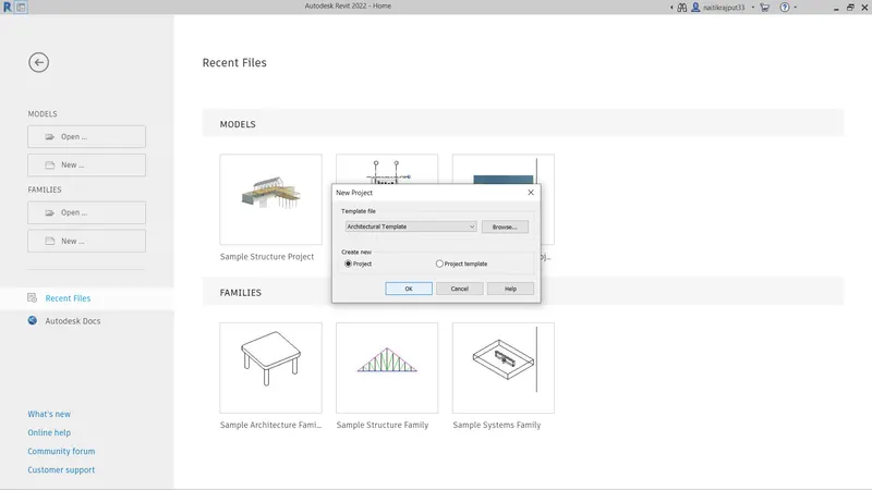
After, main window of Revit will open, go on to New option under Models option. New-->Project option. A new project dialog box will open. Select Architectural template under template file and project and click on OK button.
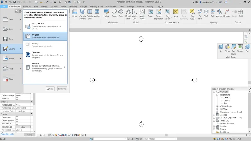
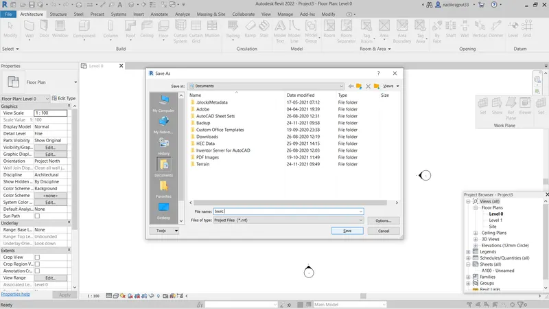
- We can save our project by going to File menu--> Save As-->project. Then give a desired name and location to our project and Click on Save button.
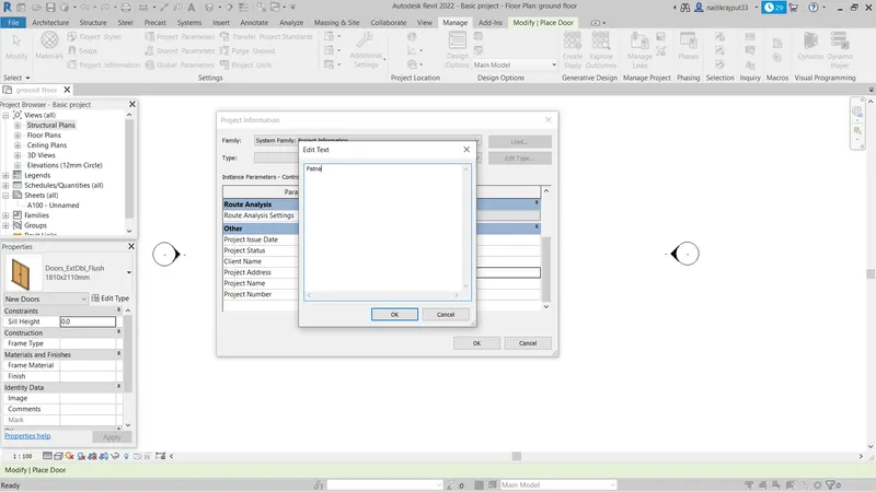
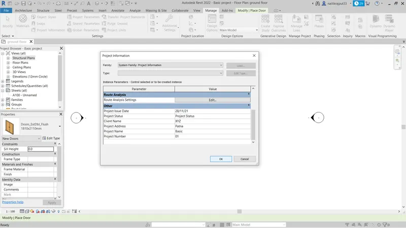
Now, go to manage option under menu bar and select project information option there. In project information dialog box add the details you desire and click on OK button.
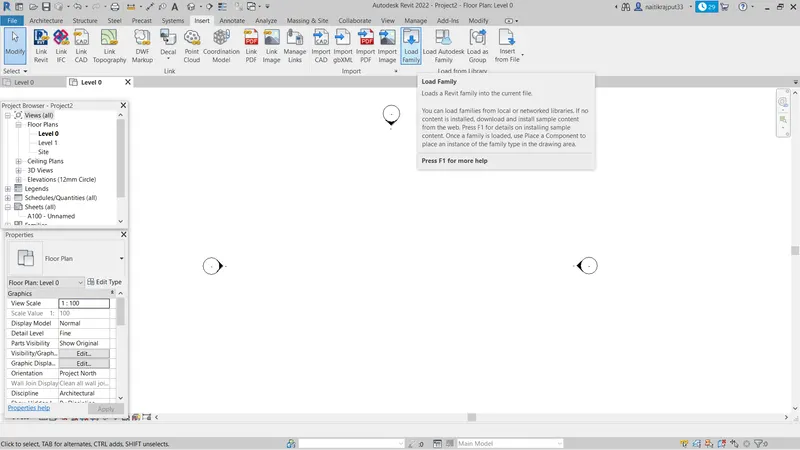
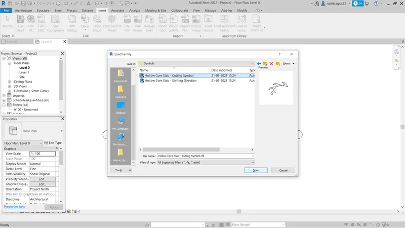
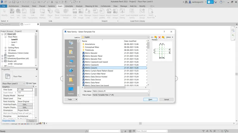
- Now go to insert option -->> load family. Select a family and click on Open button.
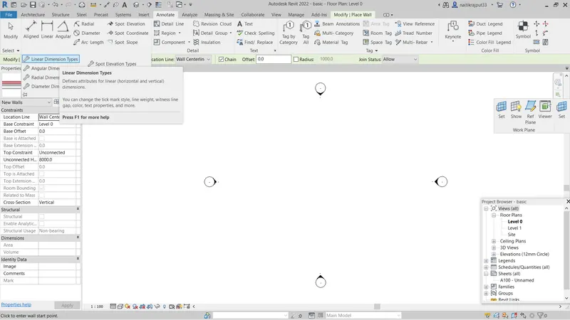
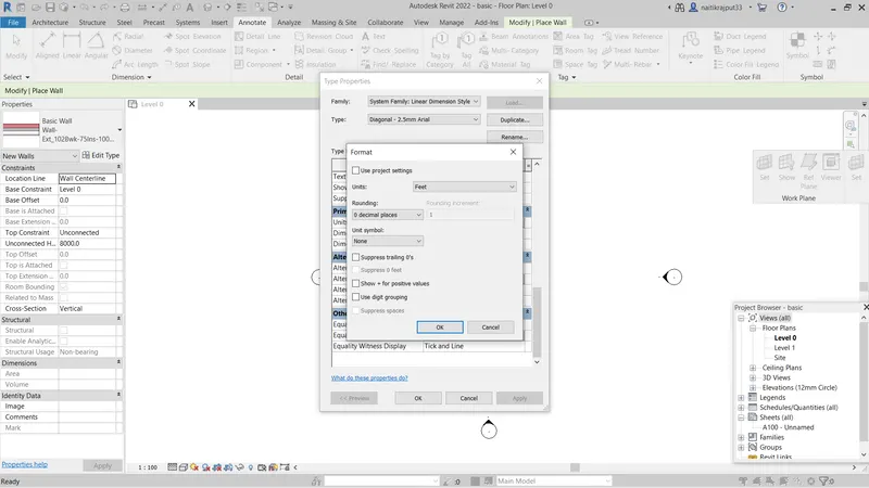
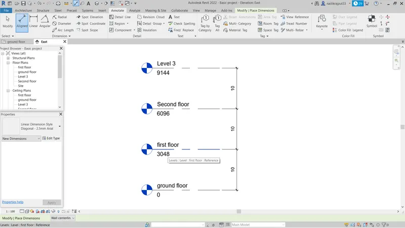
- Now, go to annotate option in menu bar and select dimensions-->linear dimension type. Properties window will open. Set primary units in the unit we desire and click OK.
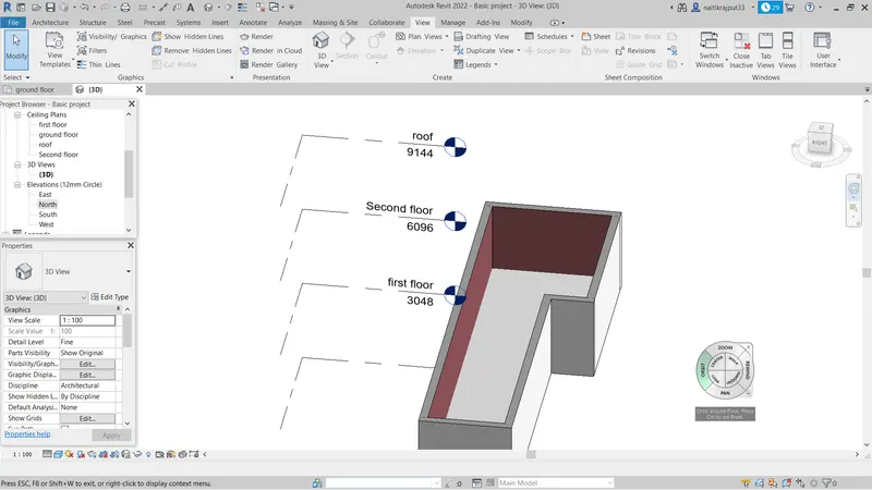
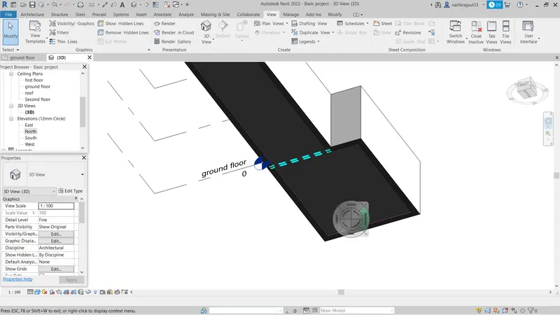
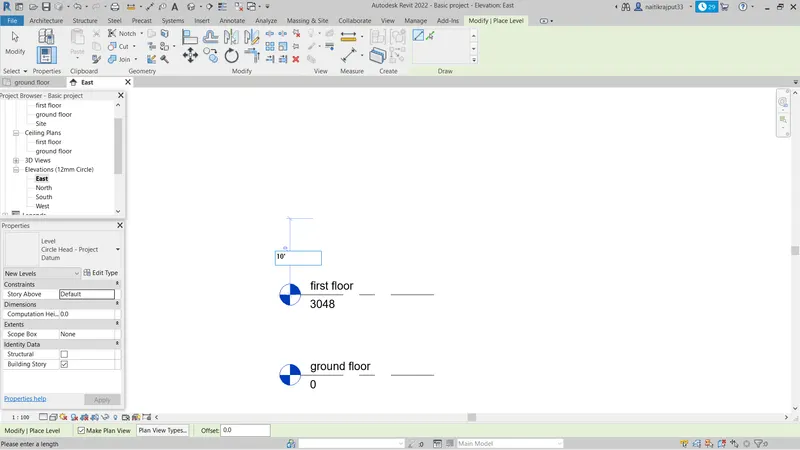
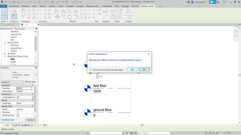
- Now, go to Elevations option under Project Browser window. Set the levels at desired height and name them with desired names.
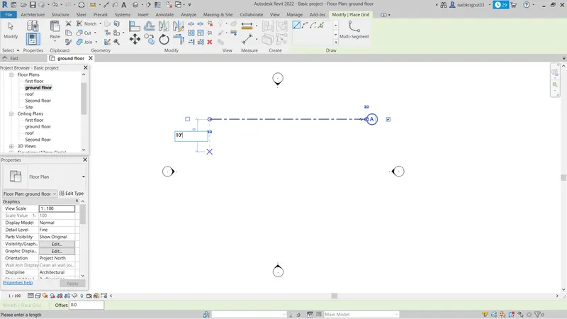
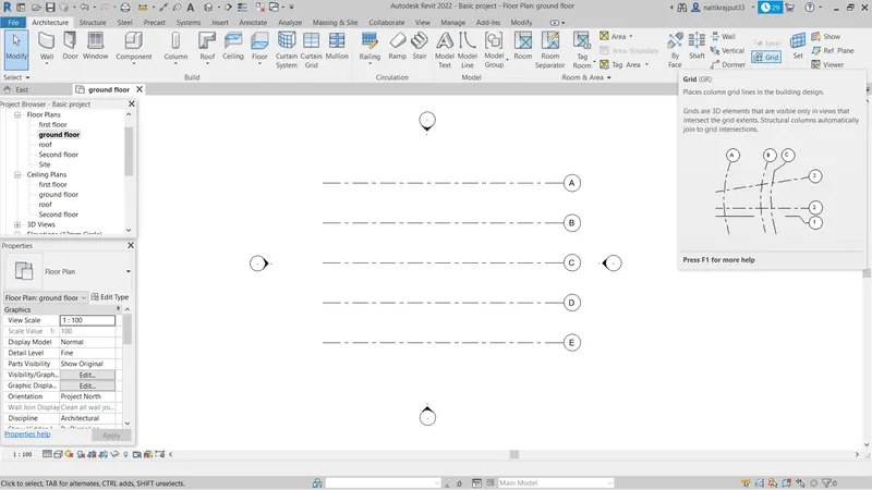
- Now go to Architecture option-->> Grids. Draw the required horizontal and vertical grids at desired spacing.
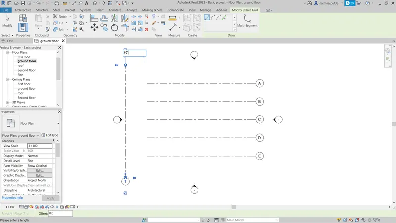
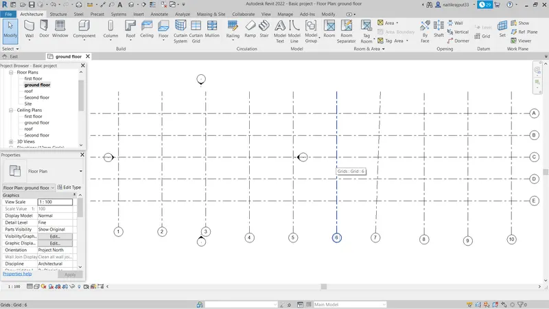
Now we will start Basic 3d modelling of a resisedential building.
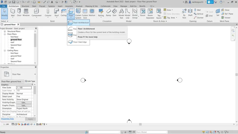
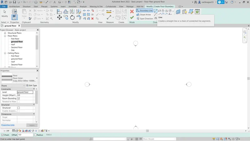
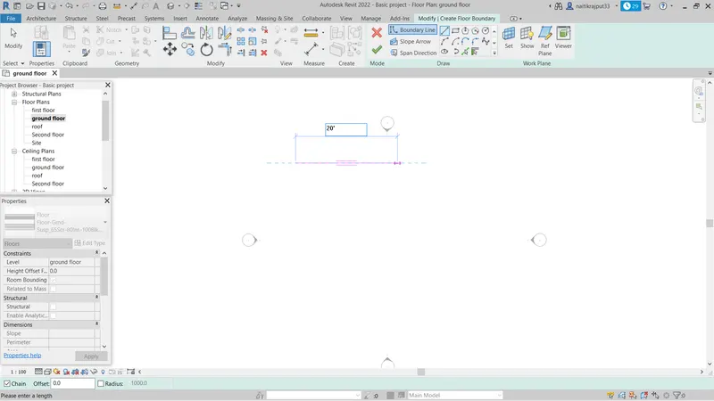
- Go to Architectural-->>Floor option. Select the desired floor type and Draw the floor using Line tool and desired dimensions.
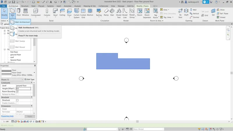
- Now, again go to Architectural and select Desired wall type and draw the wall using pick line tool.

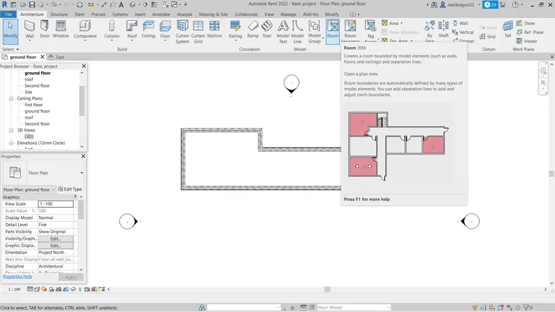
- Now, go to Architecture tab again and select Room option. Select the area under our plan for room. Select Room separator option to separate the rooms. For Area calculation select area option.
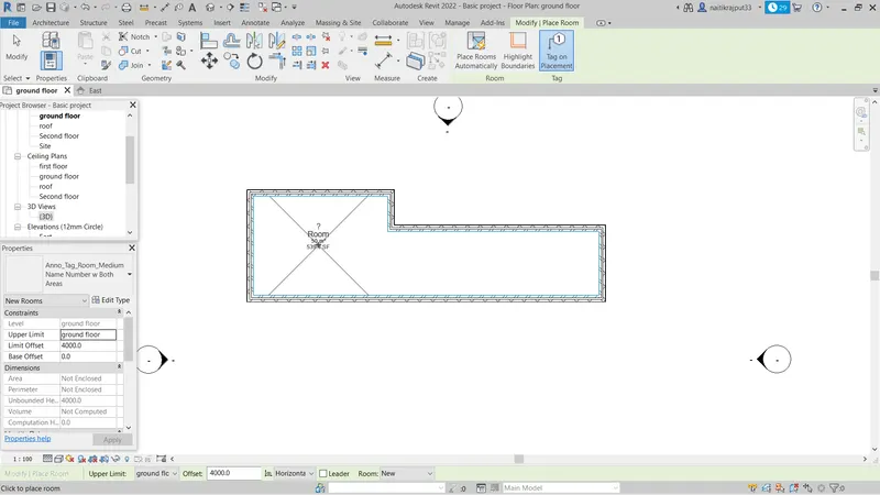
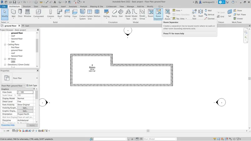
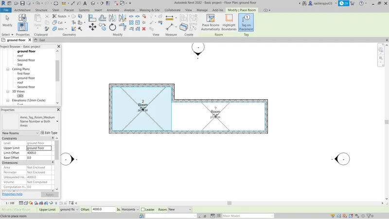
- We can give our desired name to rooms.
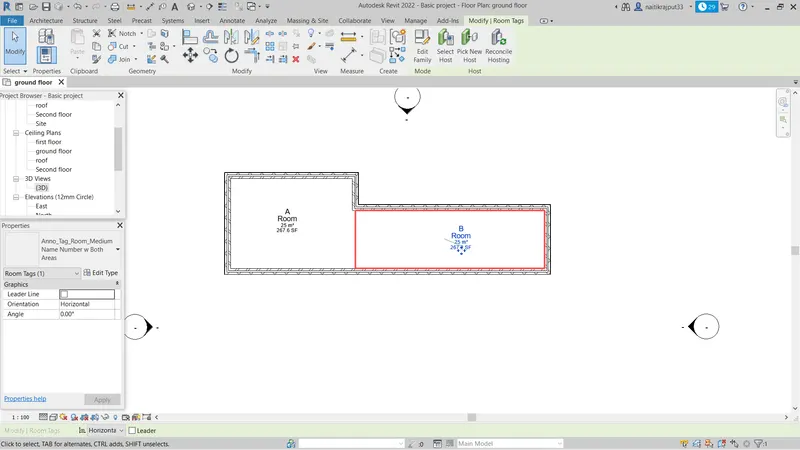
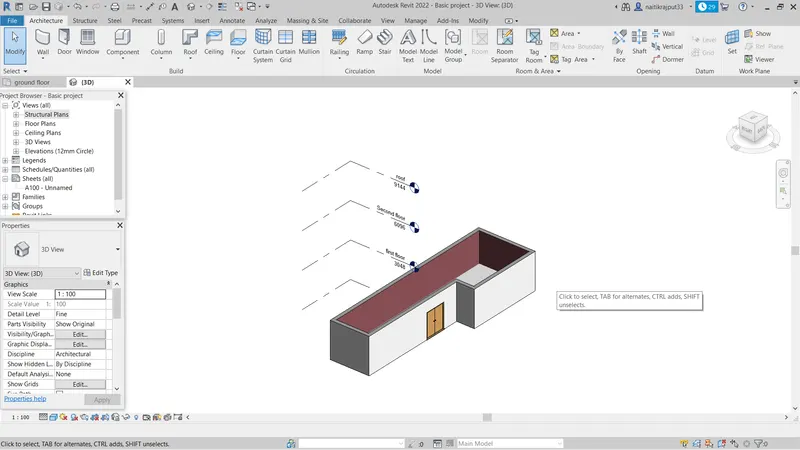
- We can also add doors at desired location by selecting door option from Architectural tab and adding it to desired place.
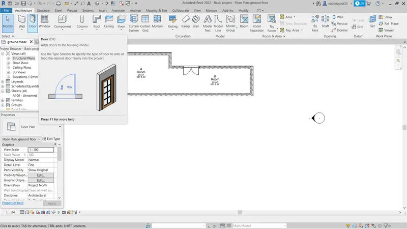
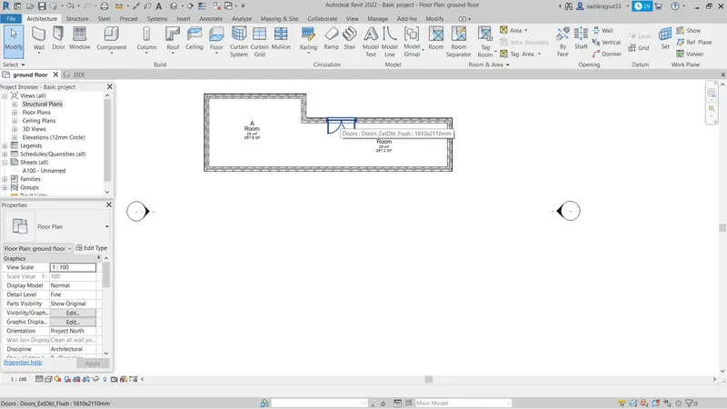
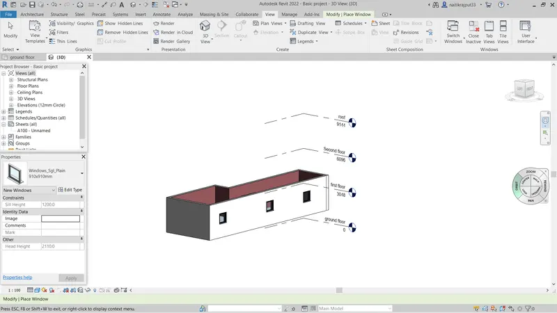
- Add window by going to architectural -->> window. Add window at desired place.
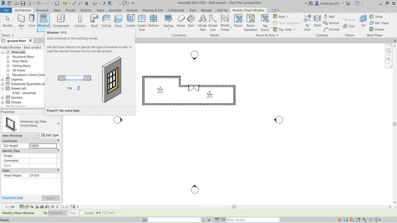
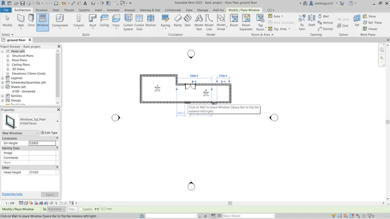
- Go to File -->> Save option to Save our project for further use.
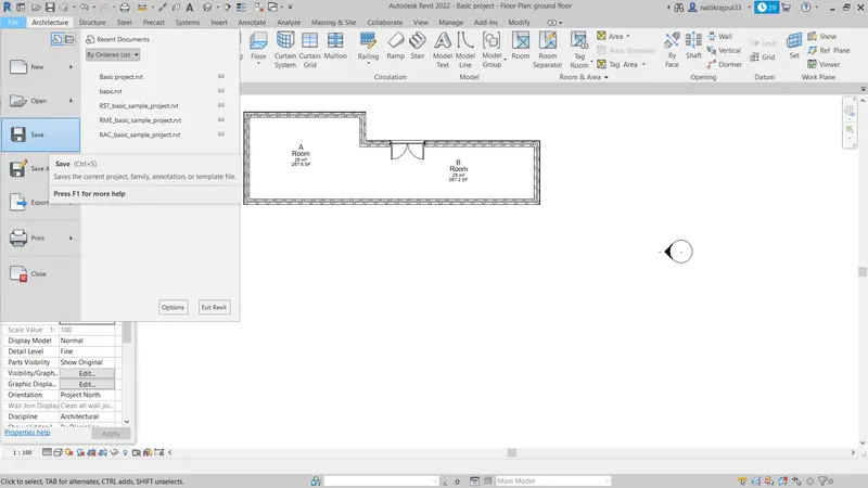
- Go to annotations tab and give dimensions to model.
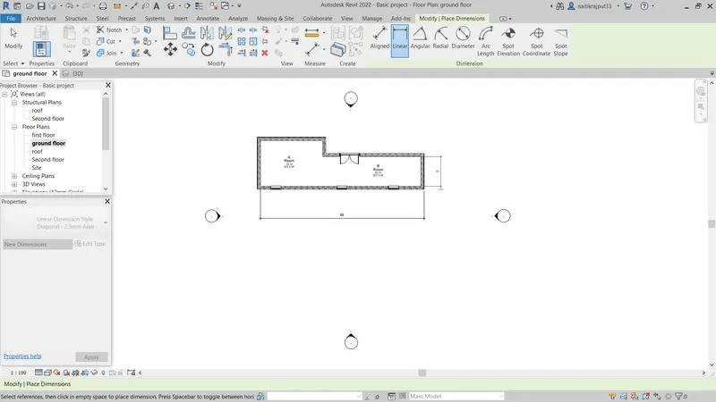
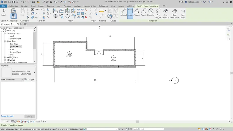
Our Basic project is ready for further use. Results we obtain are as follows which can be viewed by going to View option-->>3D view :-