Creating Architectural and Structural model with 3D rendering using REVIT
1) Select the type of structure you want to build from one of the three below:
a. Multi-Unit Residential Apartment
b. Office Buildings
c. School
ANSWER: -
Here, i would like to build and model the structure of an multi-unit residential building.
2) Assume reasonable assumptions for geographic and location details for your project modeling. Based on assumptions and type of structure selected identify the modeling requirements from NBC
ANSWER: -
The multi-residential building is planned to be constructed in Siddipet town of Telangana.
- Open the revit architectural template and click on the manage tab, and set the project location co-ordinates under the projection location tab.
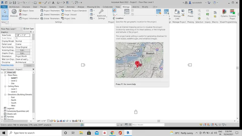
- Initially the project location is at the Boston, North America and the project is meant to be located at the Siddipet of Telangana state, India.
- By using the mouse left and the right click and scroll the project location point is set at a particular latitude and longitude coordinates at the Siddipet town of the Telangana state.
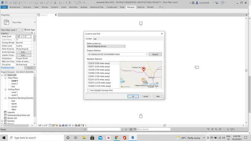
- Hence, the geographic and location details of the project have been set and now the project is ready for the modeling.
- Modeling requirements for the multi-storey residential building as per national building code are as follows: -
- As per national building code, the building is categorized as the residential building.
- The maximum height of the building shall not exceed 1.5 times the width of the road abutting plus the front open space, subject to the requirement of front open space of 16m.
- Here, in the project the building is modeled for five floors at a height of 12' for each floor, therefore the total height of the building is 60' (18.2m). The width of the road abutting the building is taken as 45'. Hence, the height of the building is within the prescribed limits as per NBC.
- The plinth height of the building shall be not less than 45omm (1.48’) from the surrounding ground level. The plinth height of the building is considered as 2'.
- Considering the type of construction as type 2 construction, the fair value for the residential building shall be taken as 2.0
- Here, in the project the residential house plan with the office is 80' and 70' respectively. This is a G+5 south facing house plan building. The total built up area of the ground floor and all the floors is 5400 sqft. The total area of the land is 7200 sqft. The floor area ratio obtained as 1.34 < 2.0. Hence safe.
According to NBC 2005; clause f-3.4, the minimum height of rooms and spaces should be
A) habitable room - 2.75m
B) kitchen - 2.6m
C)corridors - 2.1m
D) bath/ water closet - 2.2m
- In my model the height of all rooms is considered as 12' (3.6m) which is greater than the minimum wall height specified in the code. Hence it is satisfied.
- The thickness of masonry walls is given by table 2 of the fire and life safety section of the NBC 2005.
- In my model the thickness of the main walls is 9" (230mm) and inner wall 4.5" (110mm) > 100 for NBC value, hence okay.
- All the rooms in the residential unit are modeled according to the standard sizes prescribed by the national building code.
3)
Using the structural model, include the following components based on the type of structure selected
a. Foundation – Isolated / Wall/Matt Foundation
b. Columns
c. Beams Connected to Columns
d. Roof Framing/ Truss
e. Floor / Decks
f. Floor Openings for Elevators and Stairs
AIM: -
To include the structural framing components to the structure model of the multi-unit residential building.
PROCEDURE: -
- Create a new architectural model by clicking on the new options in the model section and select the architectural template from the new project dialogue box and click ok.
- Save the file to the desired folder location and name the model as architectural multi -residential building.
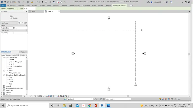
- Place the outermost reference grids to the architectural model under the architectural tab.
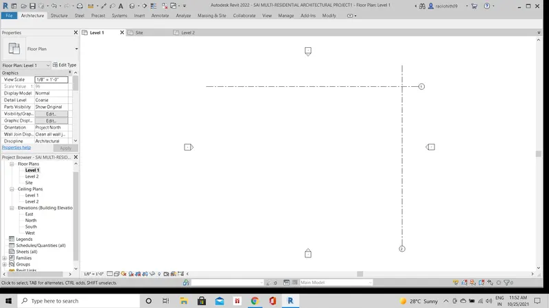
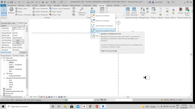
- Now in the manage menu under the project location tab click on the specify coordinates at point.
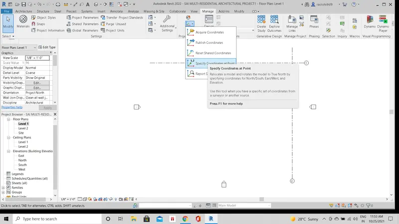
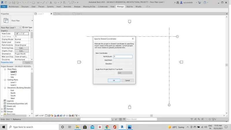
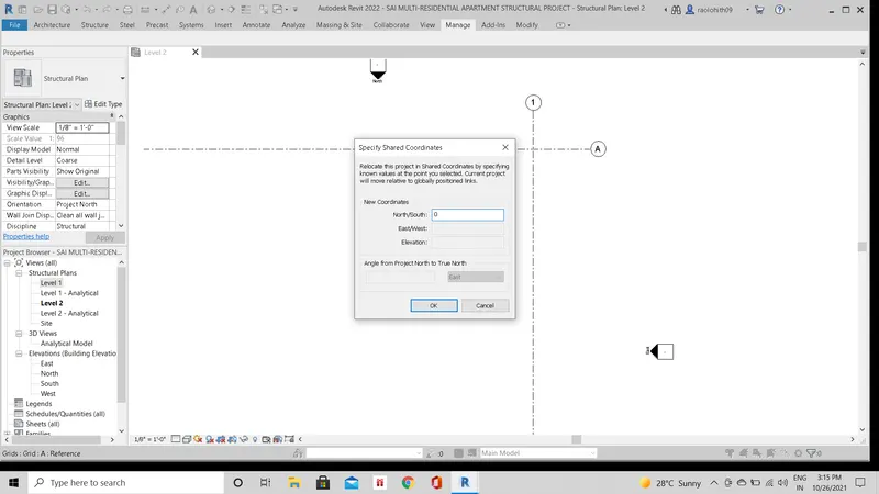
- Click on the base line grid drawn and open the specify shared coordinates dialogue box and change the north / south coordinate to 0 and click ok.
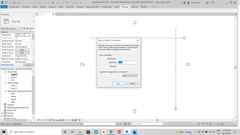
- Click on the next base line grid drawn and open the specify shared coordinates dialogue box and change the east / west coordinate to 0 and click ok.
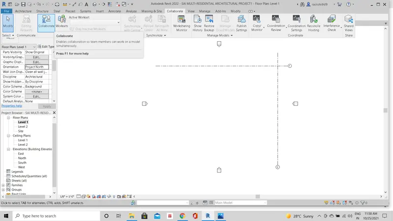
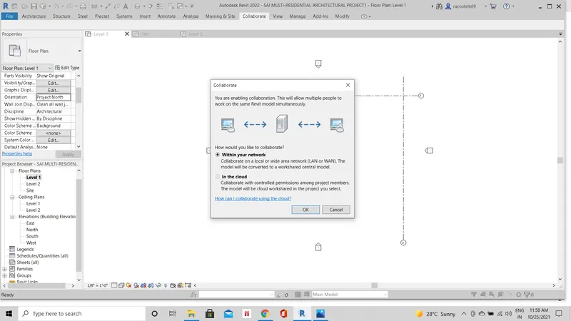
- Save the changes made to the model and go to the collaborate tab in ribbon and click on the collaborate icon.
- The collaborate dialogue box will appear and select within your network and click ok.
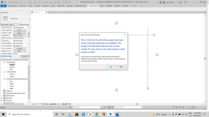
- Now save the file and save it as a central model by clicking yes in the dialogue box that appeared.
- Close the architectural model.
- Click on the new options in the model’s section and select the structural template from the new project dialogue box and click ok.
- Finally save the file to a desired folder and name the file as a structural multi- residential building.
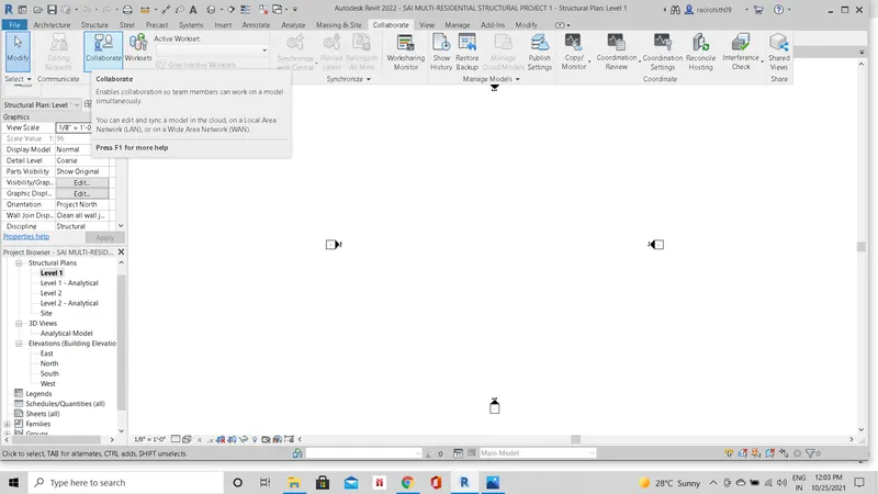
- Go to collaborate tab in ribbon and click on the collaborate icon.
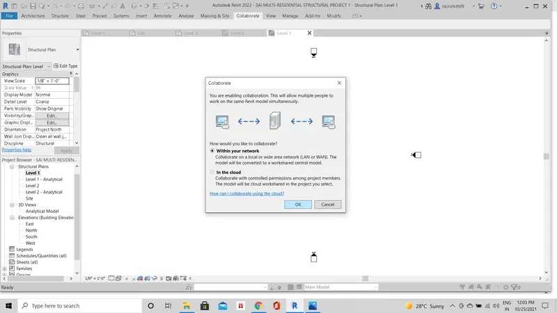
- The collaborate dialogue box will appear and select within your network and click ok.
- Now save the file as central model by clicking yes in the dialogue box that appeared.
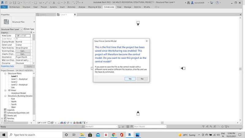
- The outermost reference horizontal and vertical grids were created as shown.
- Now in the manage menu under the project location tab click on the specify coordinates at point.
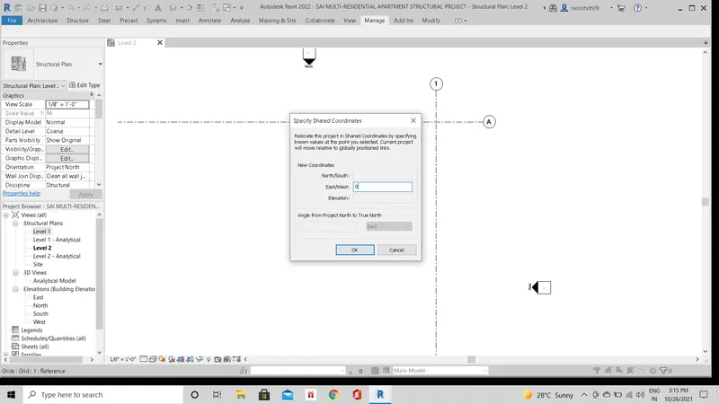
- Click on the base line grid drawn and open the specify shared coordinates dialogue box and change the north / south coordinate to 0 and click ok.
- Click on the next base line grid drawn and open the specify shared coordinates dialogue box and change the east / west coordinate to 0 and click ok.
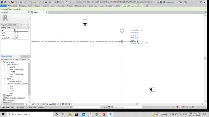
- Now the project base point is set to the structural model as o and o as shown.
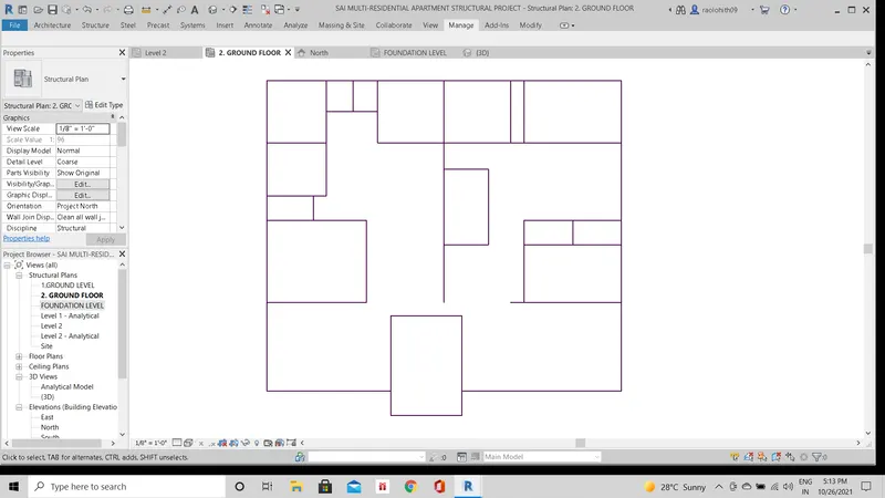
- All the horizontal and vertical grids were created. Horizontal grids are named from 1 to 7 starting from right to left and vertical grids named from A to G starting from top to bottom.
- The layout model of the multi- unit residential building is created by drawing the sketch of region of layout reference to the horizontal and vertical grids created in the ground floor.
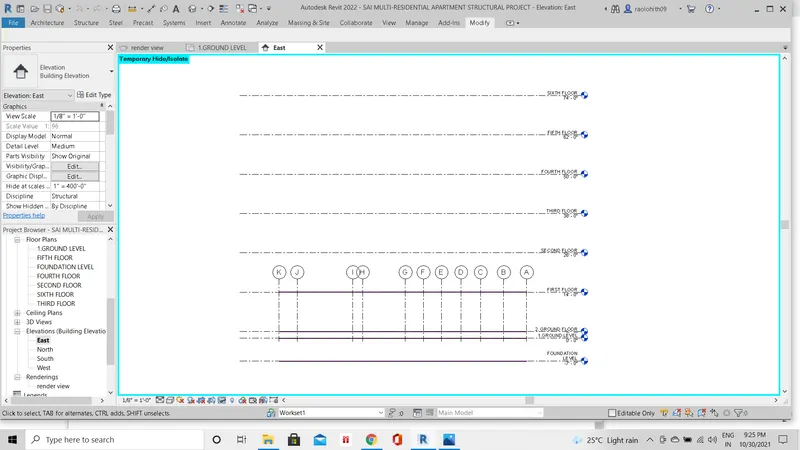
- By using the levels option in the structure tab levels up to the sixth floor was created at a height of 12' each and foundation level at a depth of 7'.
- Click on the isolated footing option in the structure tab to apply footings to the building.
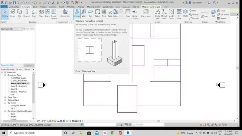
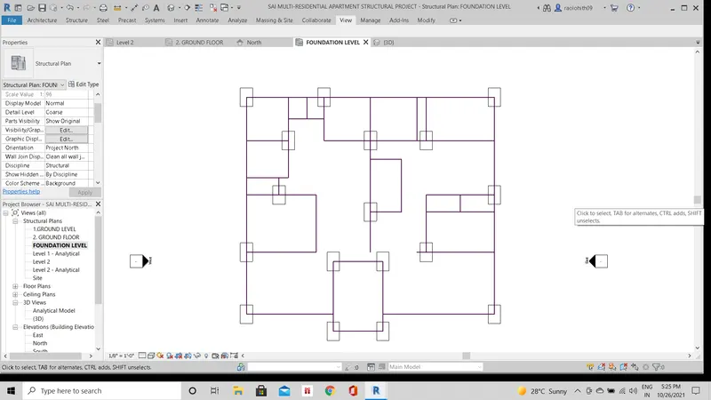
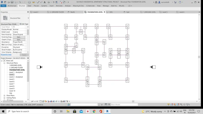
- All the footings were placed at the required intersections of vertical and horizontal lines as needed at the foundation level of the building.
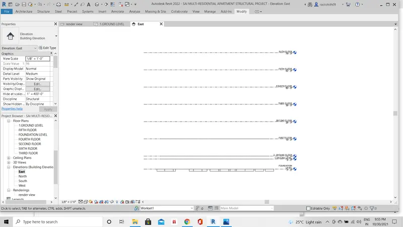
- The east elevation view showing the footings are provided below and are correctly aligned as shown in the figure.
- Click on the column option in the structural tab to place the columns on the footings applied to the building model.
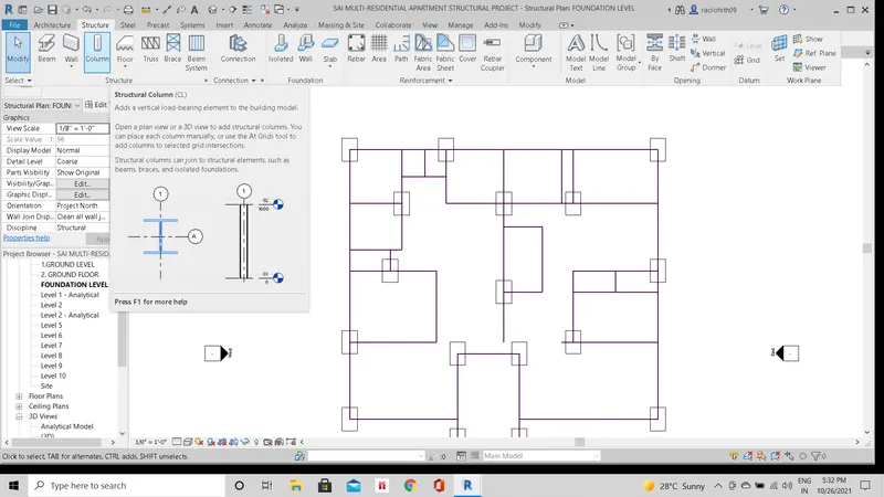
- Now all the columns are placed at the center position to the top of the isolated footing till the sixth floor level of the building.
- The beams are placed next, click on the beam option in the structure tab and select the beam of choice that aligns to the column dimensions perfectly and connect all the columns by placing the beams in between them by clicking Centre - Centre of the column .
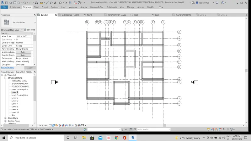
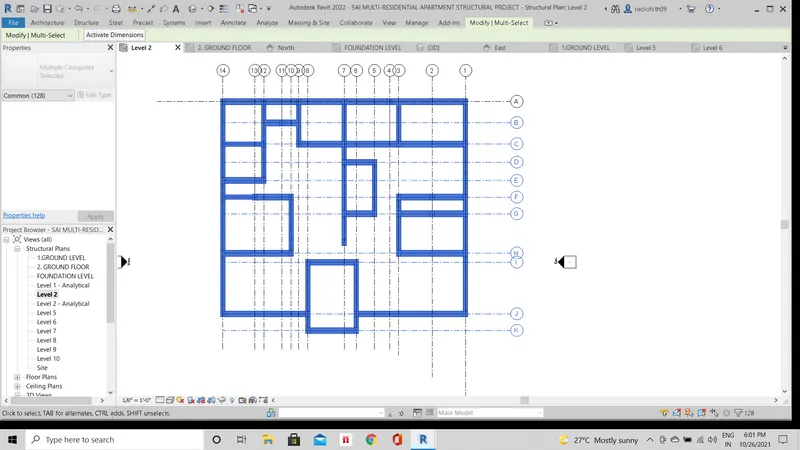
- The components of the beams and columns are placed at all the levels of the building by copying to the clipboard and then paste to the selected levels.
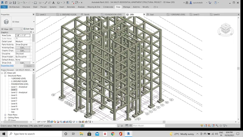
- The 3d view of all the components such as beams, columns and footings are as shown.
- D) ROOF: -
- Next task is to provide a roof to the structure.
- Here in this model the top of the structural building is not covered by the roof and it is left to the open space and considered as the terrace top of the building.
- A roof is provided to the top of the stair and lift lobby cabin of the building in the architectural model.
- E) STRUCTURAL FLOORS: -
Click on the structural floor option in the structural tab as shown.
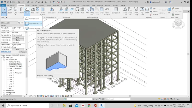
Draw the structural floor in the top level and then copy paste it to the remaining levels as shown.
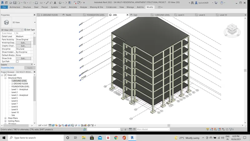
- F) SHAFT OPENINGS: -
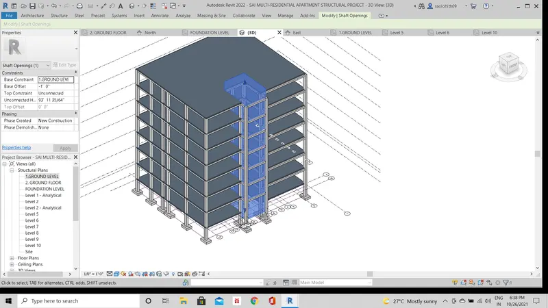
Click on the shaft opening option in the structure tab. Using the line option draw the opening portion for the shaft and select the required levels.
The shaft opening is provided till the sixth floor of the building and is as shown in the figure.
RESULTS: -
All the structural components like isolated footings, columns, beams, structural floor and shaft openings were provided to the building.
4) Using the architectural model, include the following components based on the type of structure selected
a. Wall Layout with appropriate material and finishing
b. Exterior façade with fancy finish
c. Interior partition walls to size rooms
d. Components to add details to a room (Desk, Chair, Lighting, plumbing fixtures)
e. Add components such as stairs Elevators
f. Have at-least one side of the building with curtain walls and glass panels
g. Include interior and exterior lighting fixtures
h. Place proper topographic components from outside (Trees, Parking, Plants) to add details to the model
AIM: -
To place the architectural components to the multi- residential architectural building.
PROCEDURE: -
- Initially we have to link the architectural and the structural template.
- For this, first open the architectural template and then insert the structural template into it.
- For this, go to the insert tab ----> revit links----> choose the links.
- Using the copy monitor copy all the components to the architectural template.
- Now the architectural model and structural model is linked.
- Wall Layout with appropriate material and finishing
Wall layout has been developed. Wall thickness provided is 12". Now, we have to assign the material to the wall. Here along with the wall the curtain wall is placed at the front portion of the stair lobby of the building as shown in the figure.
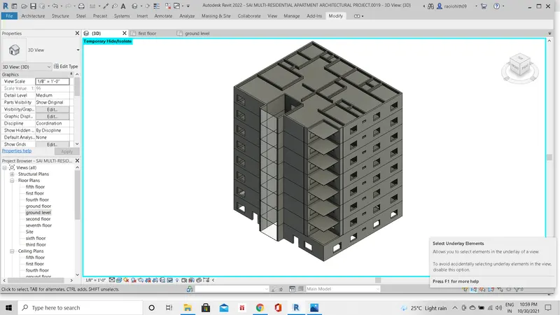
Here the type of wall material selected as concrete masonry of 12'' thickness.
After the wall is designed all the necessary doors and windows was provided in the exterior wall as shown in the figure.
- Exterior façade with fancy finish
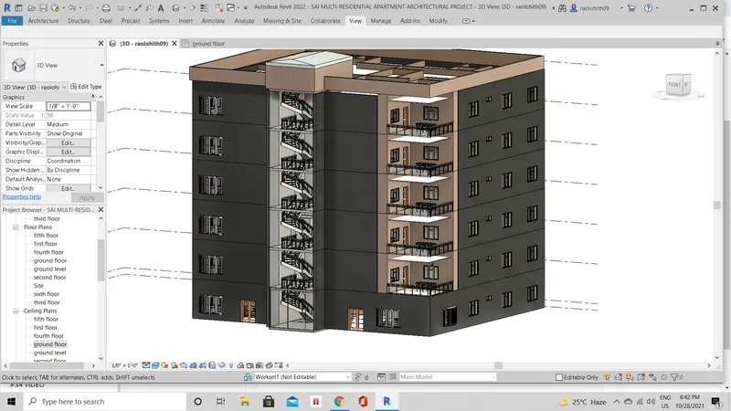
Exterior facade with fancy finish was provided as shown.
c. Interior partition walls to size rooms
d. Components to add details to a room (Desk, Chair, Lighting, Plumbing fixtures)
e. Add components such as stairs Elevators
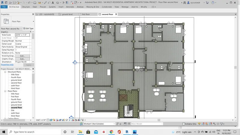
The interior partition walls, components were provided next as shown in the figure
f. Have at-least one side of the building with curtain walls and glass panels
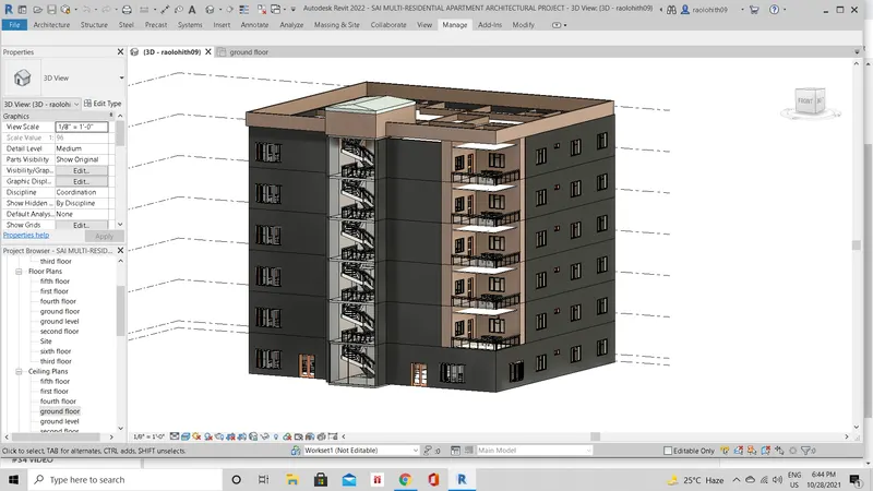
The front side of the building of the stair lobby is covered with the curtain wall.
g. Include interior and exterior lighting fixtures
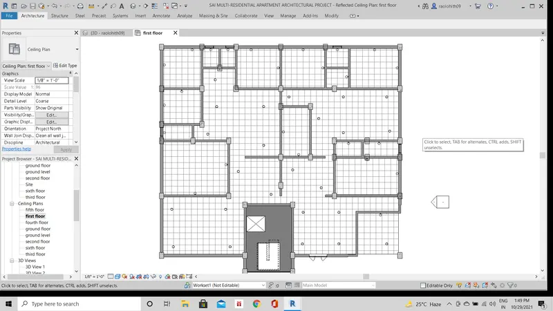
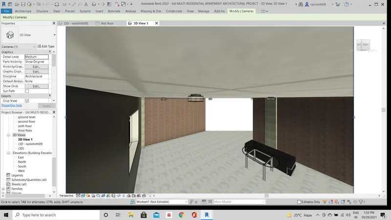
The interior lighting provided is as shown by going to architecture tab---> components ----> load family ---> and then place the exterior light components at the required locations.
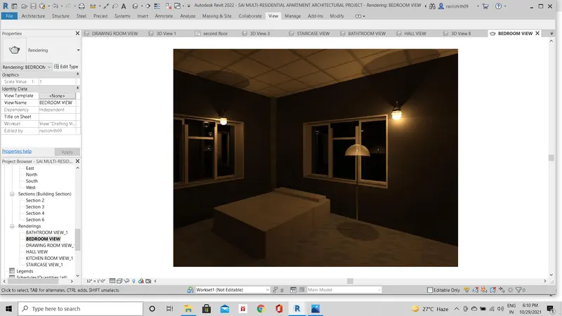
The interior lightings provided with ceiling lights, floor lamps and wall lamps as shown in the figure.
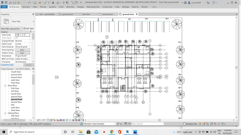
The exterior lighting provided is as shown by going to architecture tab---> components ----> load family ---> and then place the exterior light components at the required locations.
h. Place proper topographic components from outside (Trees, Parking, Plants) to add details to the model
For the topographic components, go to architecture tab---> components load family ----> select plantings and place shrubs and other plants.
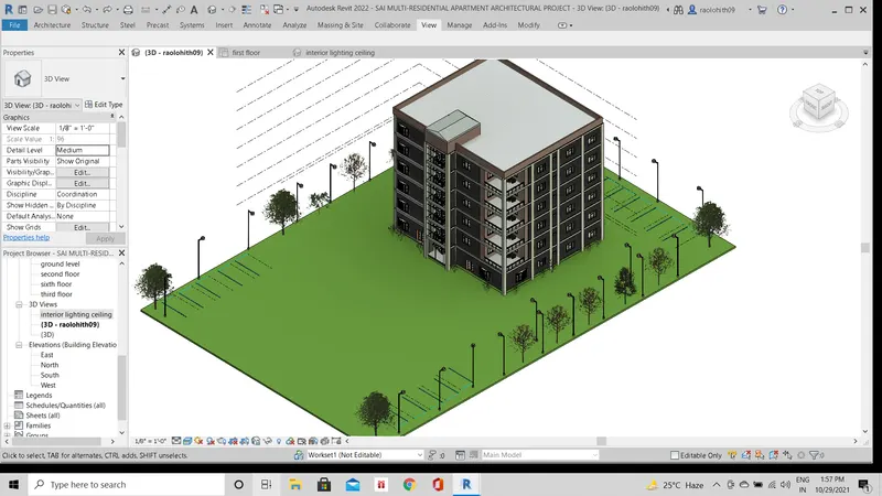
Already while providing the lighting itself all the topographic components was placed at that time itself.
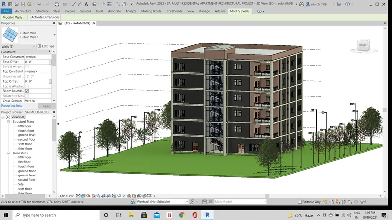
3d isometric view of the building is as shown, it shows the topographic details of the building.
RESULTS:
The following components was included in the architectural model: -
a.Wall Layout with appropriate material and finishing
b. Exterior façade with fancy finish
c. Interior partition walls to size rooms
d. Components to add details to a room (Desk, Chair, Lighting, plumbing fixtures)
e. Add components such as stairs Elevators
f. Have at-least one side of the building with curtain walls and glass panels
g. Include interior and exterior lighting fixtures
h. Place proper topographic components from outside (Trees, Parking, Plants) to add details to the model
5) Provide a set of drawings in an architectural and structural model to list the following details with categories and appropriate sheet templates included
a. Floor Plans with Annotations
b. Elevations
c. Sections
AIM: -
To provide the following sheet templates:
- Floor Plans with Annotations
b. Elevations
c. Sections
PROCEDURE: -
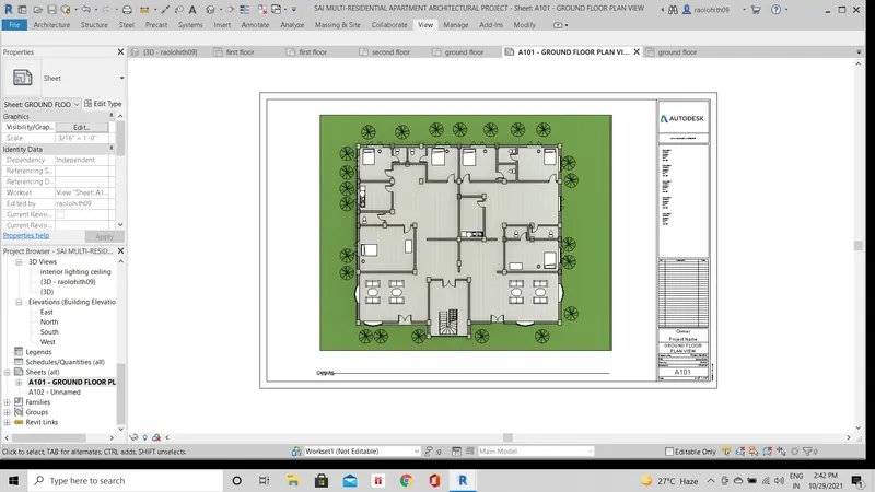
GROUND FLOOR PLAN
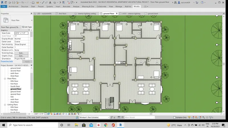
Initially all the floor plans were properly annotated as shown. The ground floor plan of the building is shown in the figure.
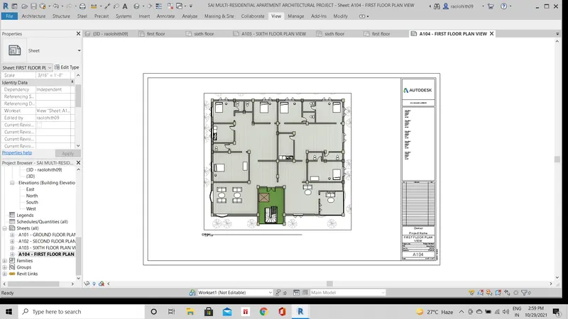
FIRST FLOOR PLAN
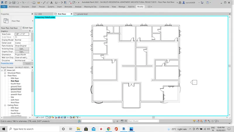
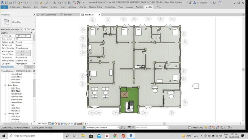
All the floor plans from the first floor to the fifth floor are same. The first-floor plan of the building as shown in the figure.
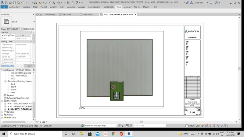
SIXTH FLOOR PLAN
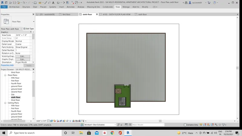
The sixth-floor plan of the building is as shown in the figure.
SHEET TEMPLATES:
Now all the views were added to the template as shown
GROUND FLOOR PLAN:
FIRST FLOOR PLAN:
SIXTH FLOOR PLAN:
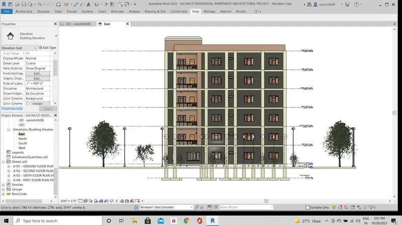
B) ELEVATIONS:
EAST ELEVATION VIEW:
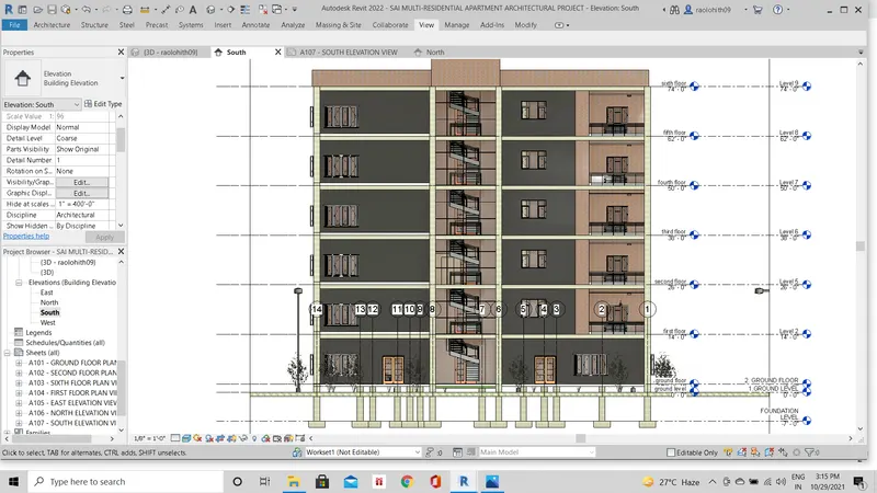
SOUTH ELEVATION VIEW:
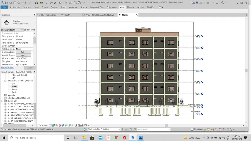
NORTH ELEVATION VIEW:
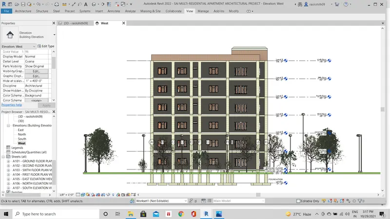
WEST ELEVATION VIEW:
NOW ADDING ELEVATIONS TO THE SHEET TEMPLATES:
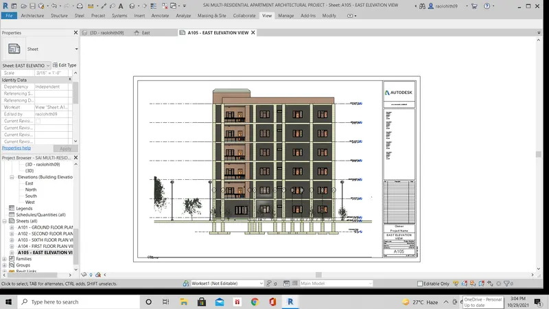
EAST ELEVATION TEMPLATE
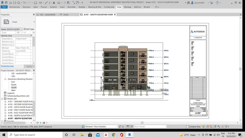
SOUTH ELEVATION TEMPLATE
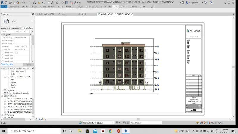
NORTH ELEVATION TEMPLATE
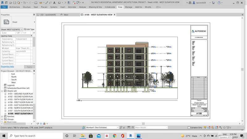
WEST ELEVATION TEMPLATE
C)
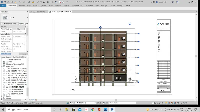
SECTION VIEWS:
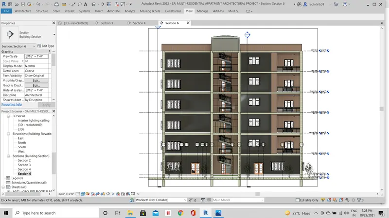
Click on the section line in view tab
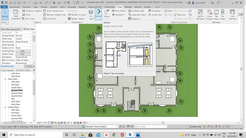
Draw the section lines through the building as required
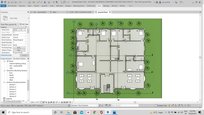
SECTION 1
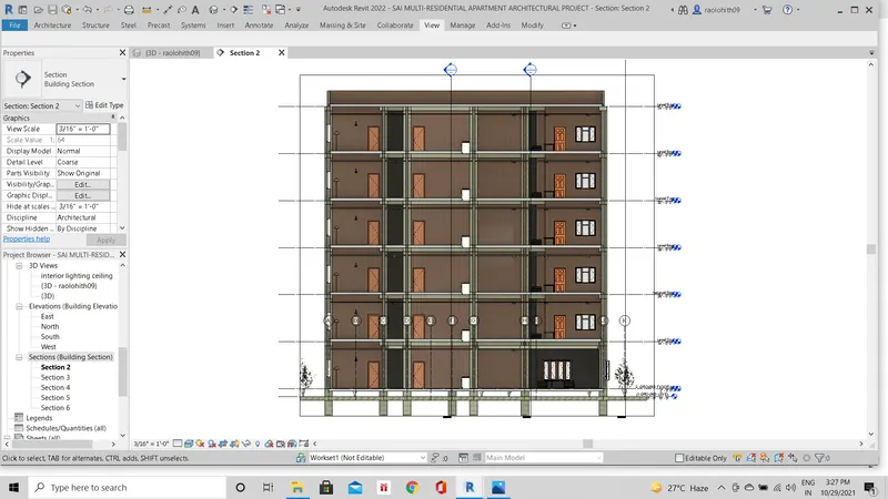
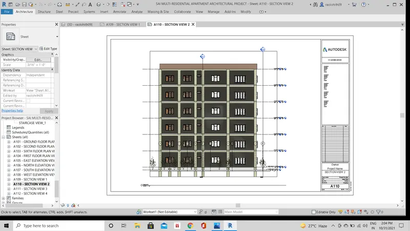
SECTION 2
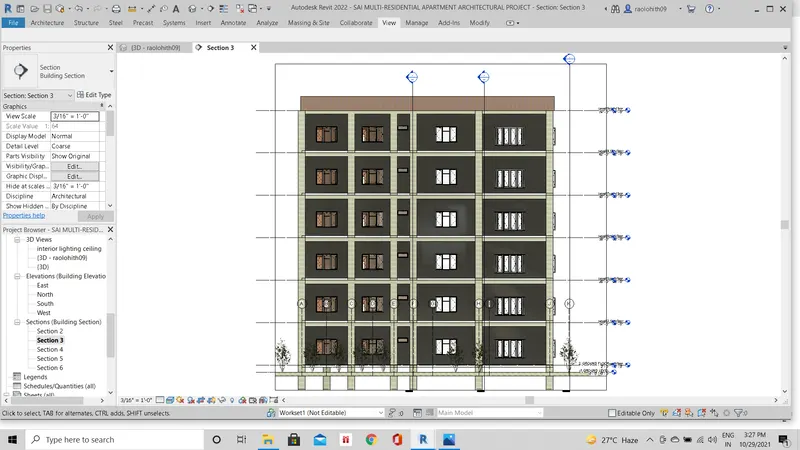
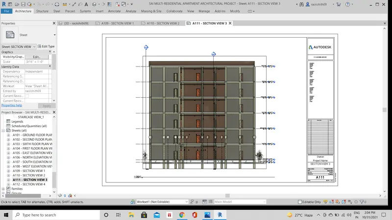
SECTION 3
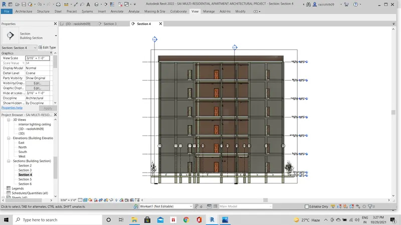
SECTION 4
SECTION SHEET TEMPLATES:
SECTION 1 TEMPLATE
SECTION 2 TEMPLATE
SECTION 3 TEMPLATE
SECTION 4 TEMPLATE
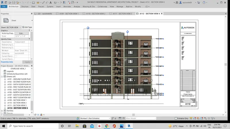
RESULTS:
The floor plans with annotations, elevations and sections were created and was placed in drawing sheet.
6) Using the Rendering settings, render images of the 3D model produced and include the rendered images to the drawing sheets
a. Rendering from interior rooms
b. Rendering from out showing topographic features
c. Rendering through structural framing
AIM:
To create the rendered 3d images of the following and to include them in the templates:
- Rendering from interior rooms
b. Rendering from out showing topographic features
c. Rendering through structural framing
PROCEDURE:
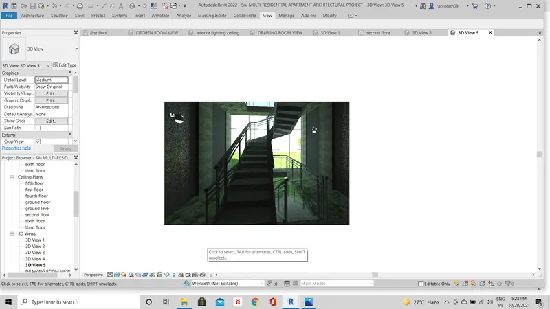
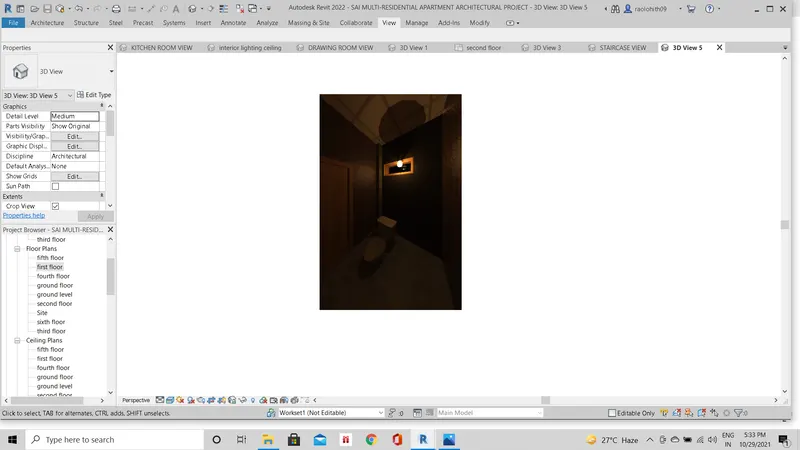
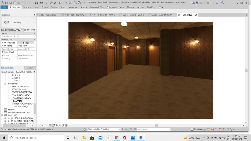
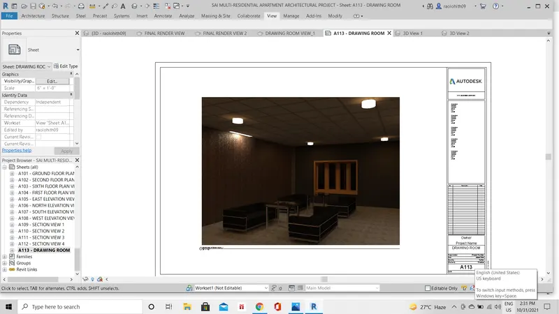
- To create the 3d rendered image first go to view ---> 3d view ---> camera.
- Then place the camera wherever required.
- Then in the view tab select render option to render the 3d image.
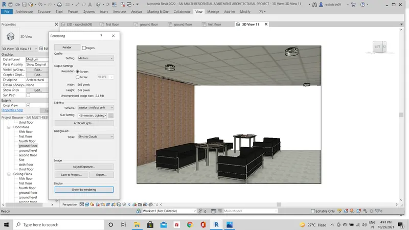
Rendering settings will be modified as follows
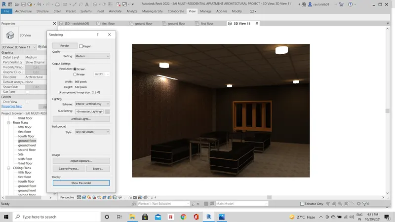
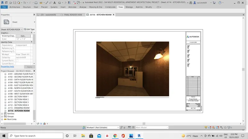
RENDERED KITCHEN
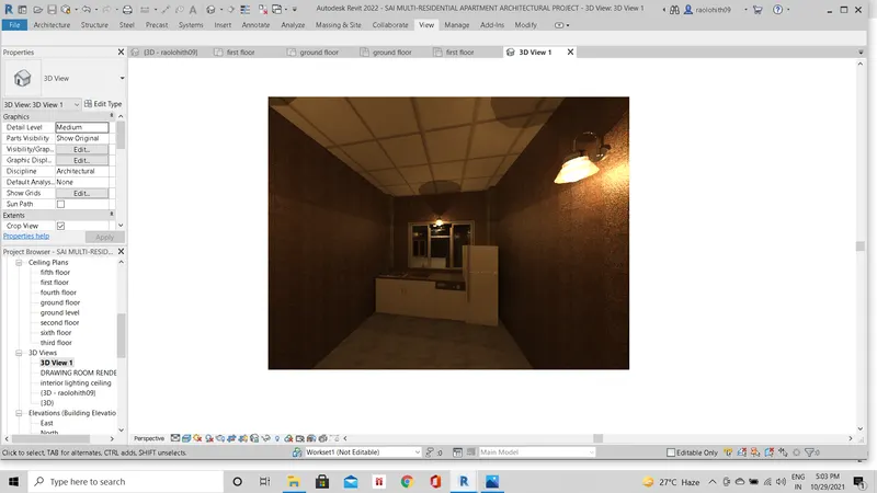
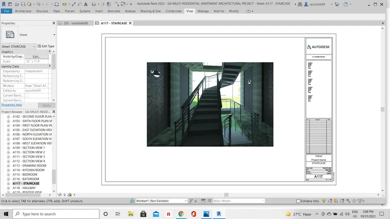
RENDERED STAIRCASE LOBBY
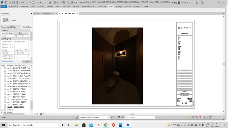
RENDERED BATHROOM
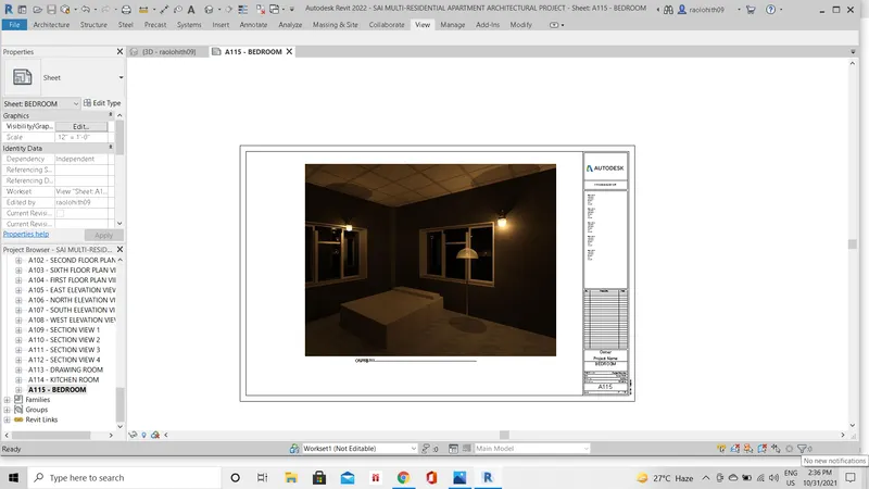
RENDERED BEDROOM
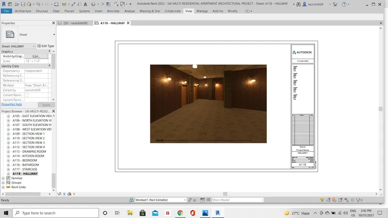
RENDERED HALLWAY
- A) RENDERED IMAGES WERE PLACED ON THE SHEET TEMPLATE AS FOLLOWS:
DRAWING ROOM
KITCHEN
STAIRCASE
BATHROOM
BEDROOM
HALLWAY
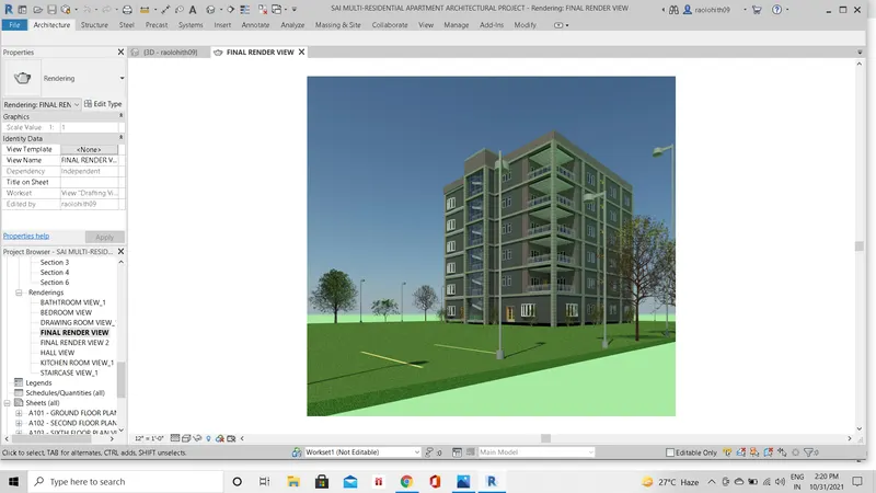
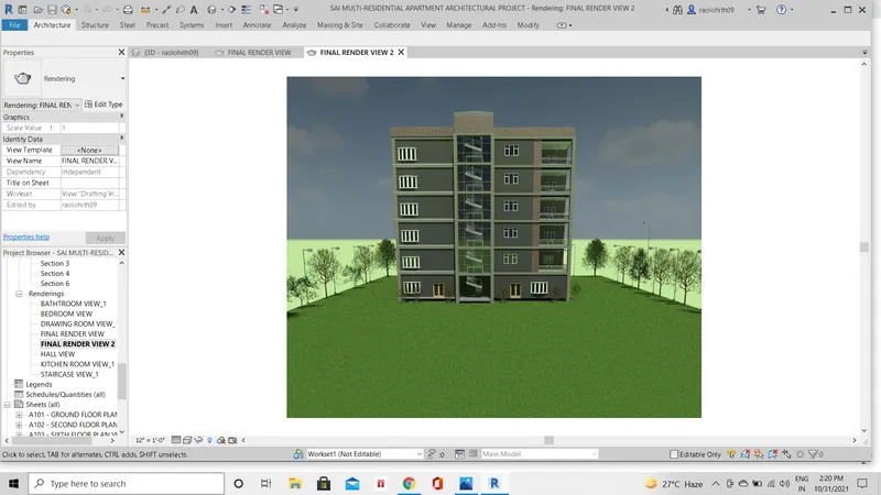
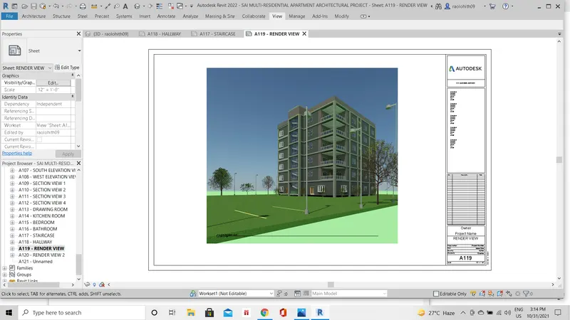
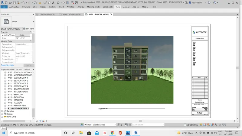
- B) OUTSIDE RENDERING SHOWING OUTSIDE GEOGRAPHY
3D VIEW 1
3D VIEW 2
OUTSIDE VIEW IN TEMPLATES:
3D VIEW 1
3D VIEW 2
- C) RENDERING THROUGH STRUCTURAL FRAMING
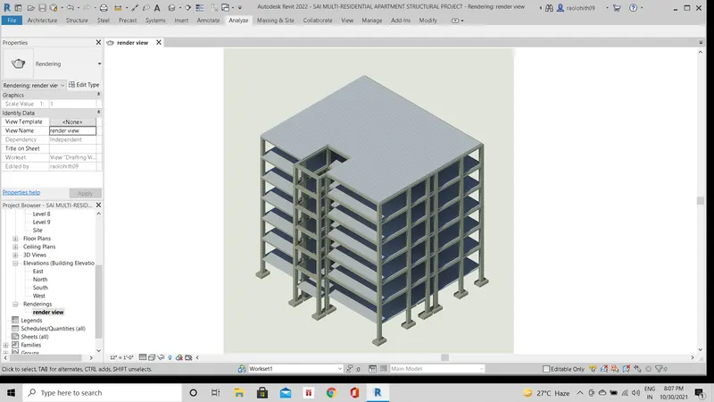
RESULTS:
The rendering from interior rooms, from out showing topographic features and through structural framing was done and is placed in drawing sheets.
7) Print the set of drawing sheets created and submit the drawings from the architecture and structure model
ANSWER:
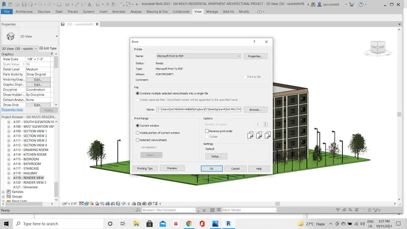
The different drawing templates can be printed. This can be done by going to the file menu in the top left corner of the revit window and in that choose print, then the following window appears and thereby all the drawing sheets can be printed.