Creating Architectural and Structural model with 3D rendering using REVIT
1) Select the type of structure you want to build from one of the three below:
a. Multi-Unit Residential Apartment
b. Office Buildings
c. School
ANS: I want to build a multi-unit residential apartment from the above given three structures.
2) Assume reasonable assumptions for geographic and location details for your project modeling. Based on assumptions and type of structure selected identify the modeling requirements from NBC
ANS:
The geographic and location details for my project modeling are assumed as:
a) My project is in a medium populated area.
b) Road width is 60’
c) Project is in plain area
d) Climate conditions are adaptable.
Modeling requirements from NBC:
3) Using the structural model, include the following components based on the type of structure selected
a. Foundation – Isolated / Wall/Matt Foundation
b. Columns
c. Beams Connected to Columns
d. Roof Framing/ Truss
e. Floor / Decks
f. Floor Openings for Elevators and Stairs
AIM: To create a project using a Structural model by including given components.
Tools Used: Grids, columns, isolated foundation, beams, roof framing, floor structural, Shaft for lift or staircase.
Procedure:
Step1: create a new file using a structural template.
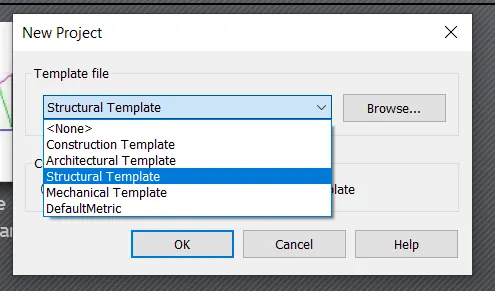
Step2: After opening save the project with an appropriate name and in the appropriate location.
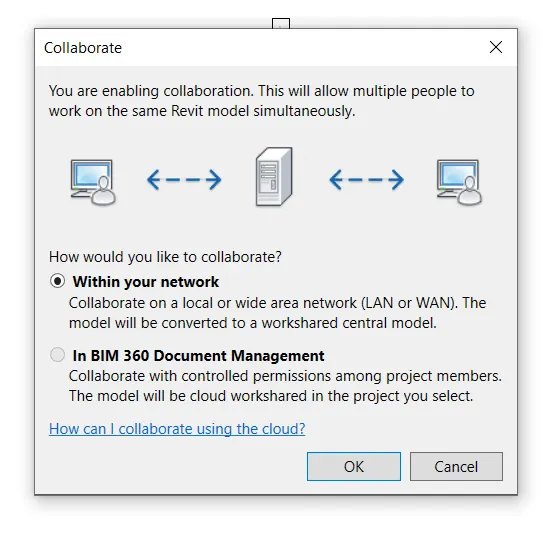
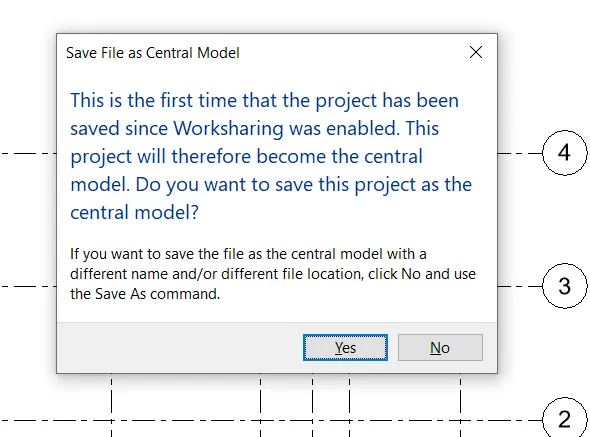
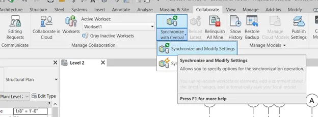
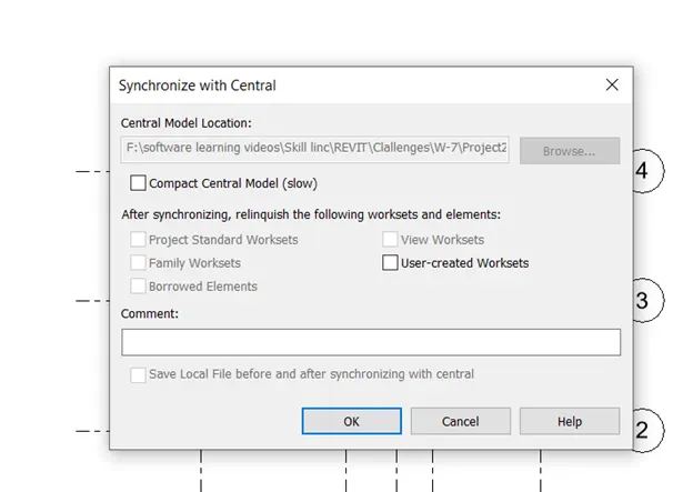
Step3: Now collaborate the file and make a central file and synchronize the settings.
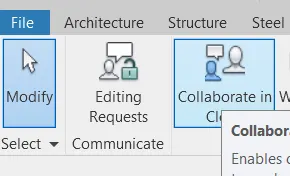
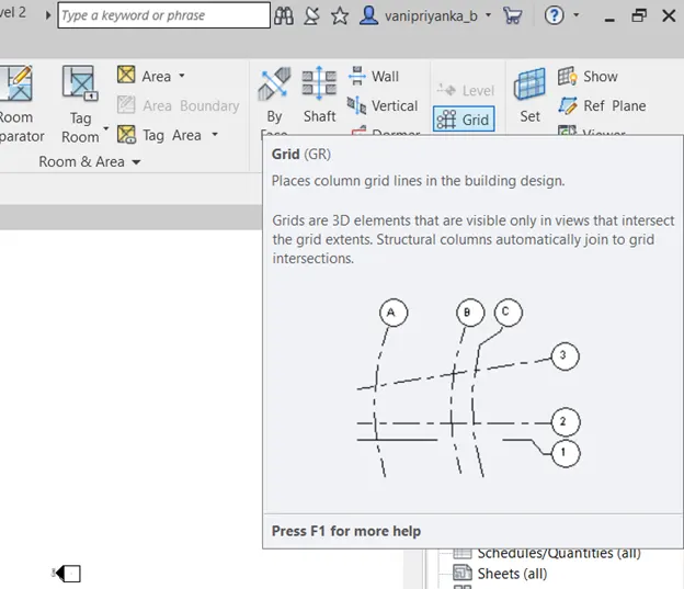
Step4: Now create the grids according to the plan taken and set the base point to origin.
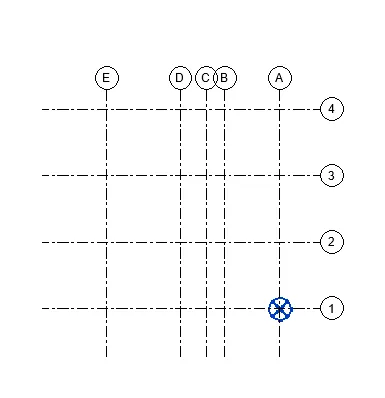
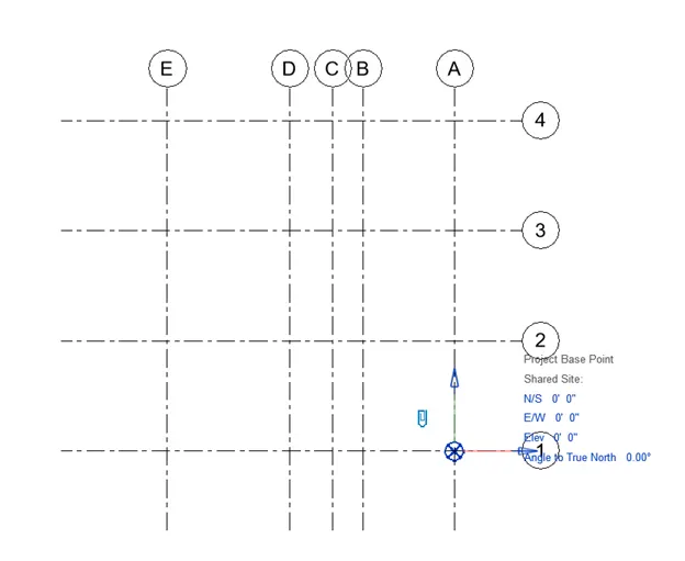
Step5: Every time while saying synchronize the file with the central file.
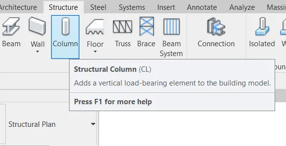
Step6: Now create the columns and isolated footings using the structural tab according to the layout.
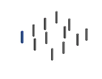
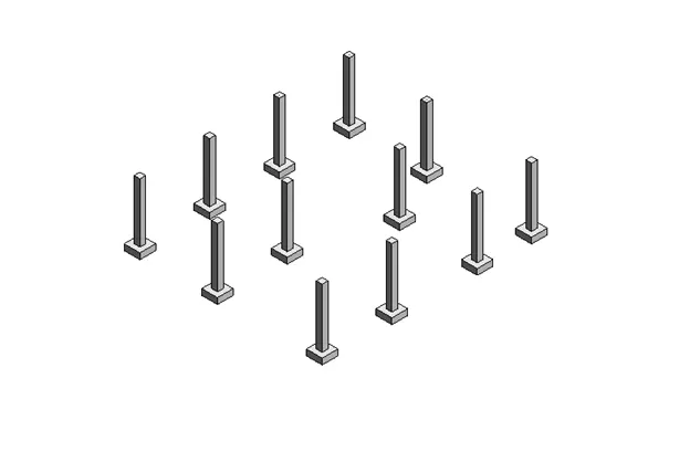
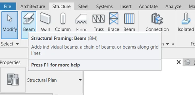
Step7: Now create the beams according to the layout.
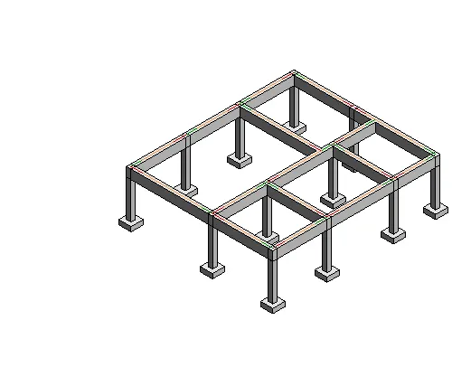
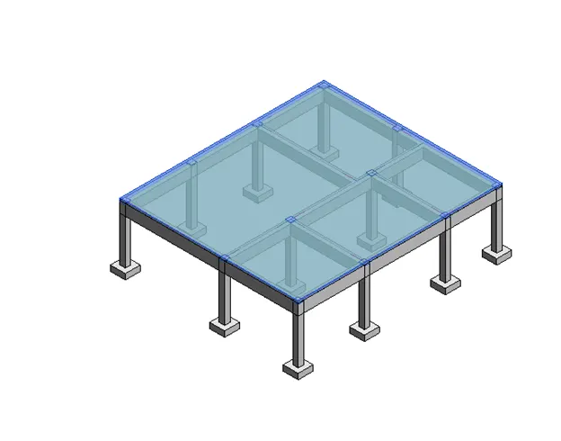
Step8: Now create the slab and draw accordingly.

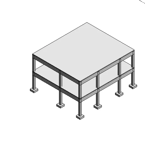
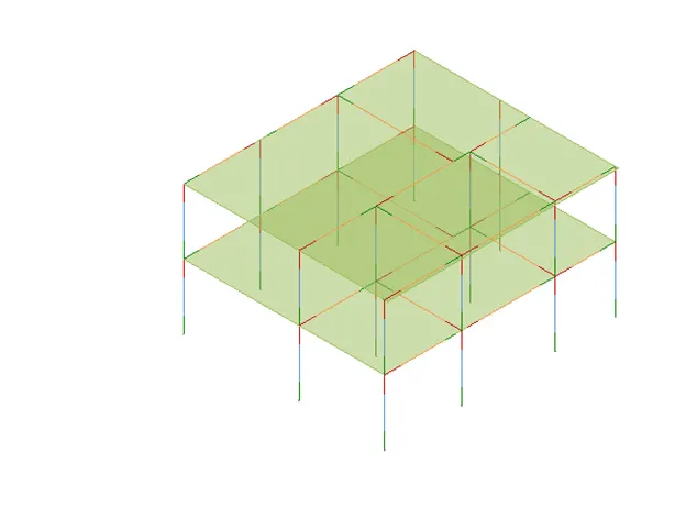
Step9: Now replicate the same layout to the next floor for multi-storied structure. And showing the 3D view and 3D analytical view also.
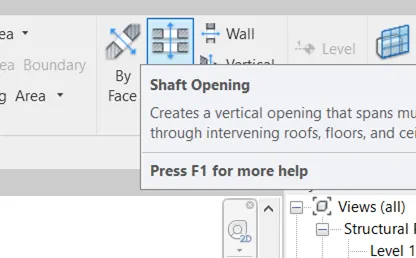
Step10: Now create a shaft opening for the staircase.
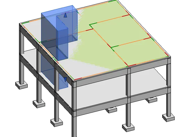
RESULT: Hence structural model of a multi-storied apartment had been created by including the footing, column, beams, slab, shaft, etc.
4) Using the architectural model, include the following components based on the type of structure selected
a. Wall Layout with appropriate material and finishing
b. Exterior façade with fancy finish
c. Interior partition walls to size rooms
d. Components to add details to a room (Desk, Chair, Lighting, Plumbing fixtures)
e. Add components such as stairs Elevators
f. Have at least one side of the building with curtain walls and glass panels
g. Include interior and exterior lighting fixtures
h. Place proper topographic components from outside (Trees, Parking, Plants) to add details to the model
AIM: To create an architectural model using an architecture template including the given components.
Tools Used: Architectural template, walls, curtain walls, floor, roof, components, ceiling, staircase, lighting fixtures, site and site components.
Procedure:
Step1: Create a new file using the architectural template.
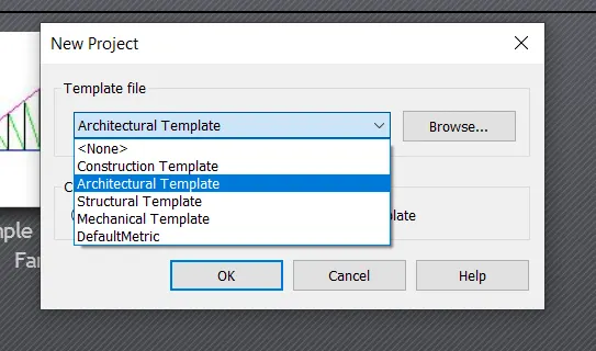
Step2: After opening save the project with the appropriate name and in appropriate location.
Step3: Now collaborate the file and make a central file and synchronize the settings.
Step4: Now create the grids according to the plan taken and set the base point to the origin.
Step5: Every time while saying synchronize the file with the central file.
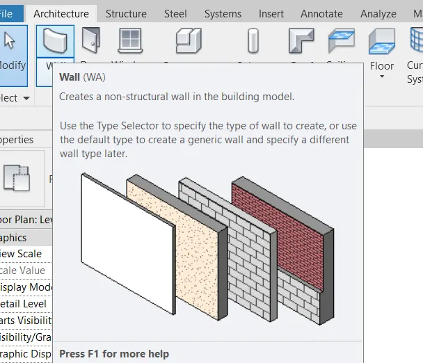
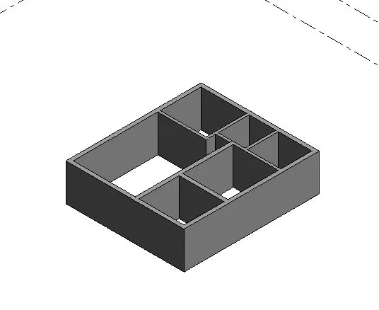
Step6: Now in the architecture tab use the wall tool to create the walls. Use edit type to create required walls.
Step7: Now place doors and windows into the plan.
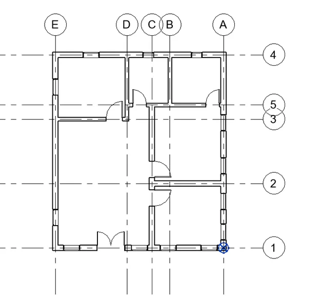
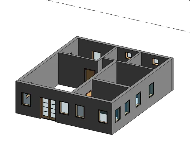
Step8: Edit the layers of the wall to give finishing.
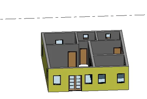
Step9: Now create the floor using floor architecture.
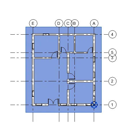
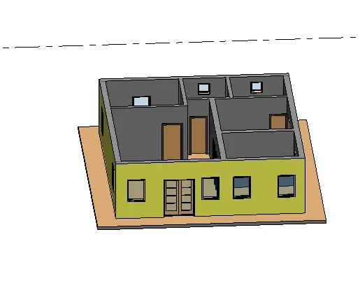
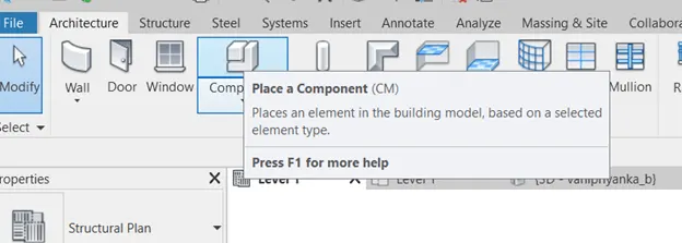
Step10: Now add the components to the model using the components tool in the architecture tab.
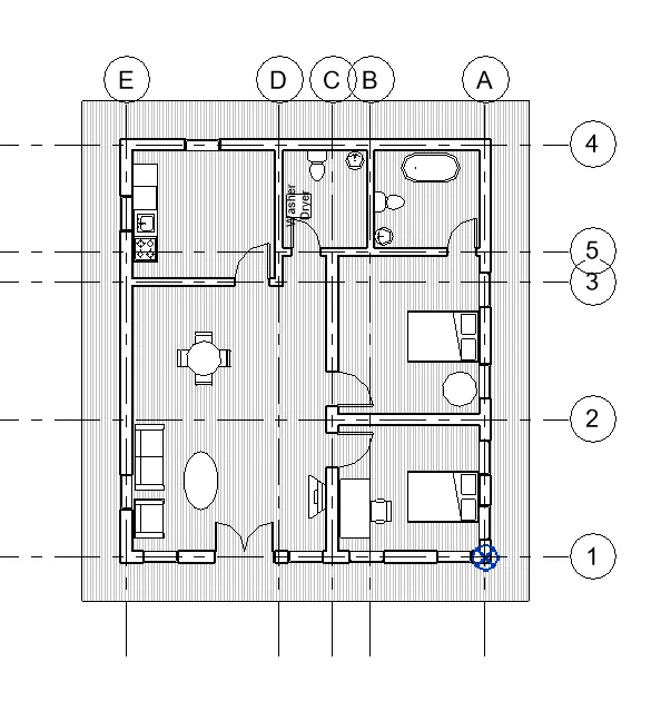
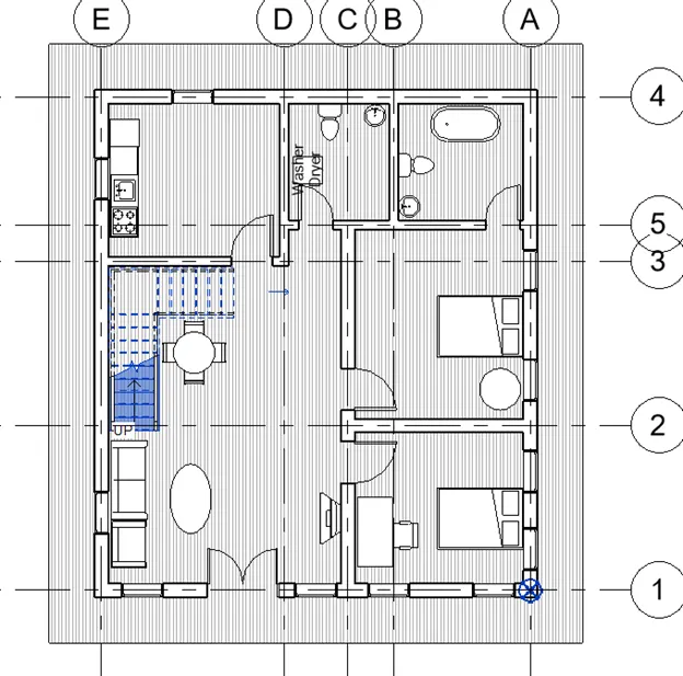
Step11: Now place the staircase and add a shaft opening also in the area of the staircase.
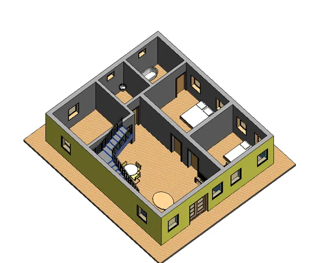
Step12: Now add the curtain wall in Children's bedroom area.
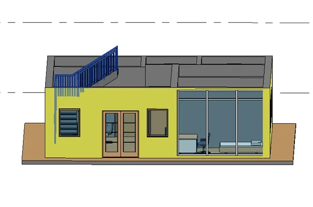
Step13: Now add the ceiling and ceiling lights and exterior lights to the model.
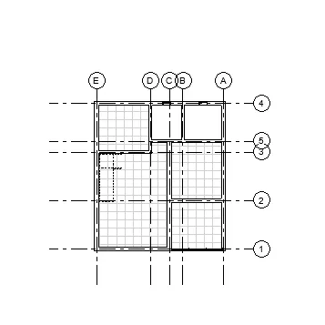
Step14: Now replicate the model to the second story to create a multi-storied building.
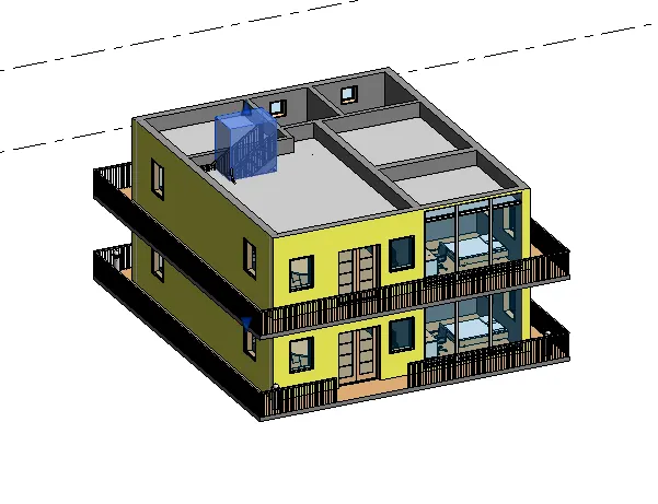
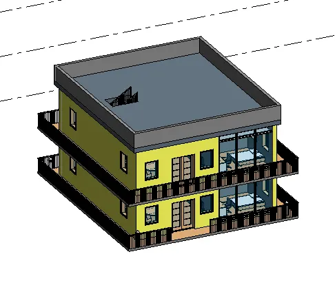
Step15: Add more details to the model like railing, parapet wall, roof, etc. now after adding 3D view is like below.
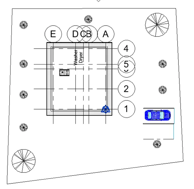
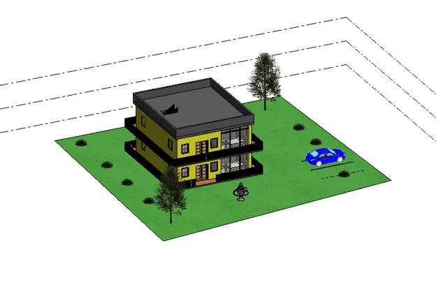
Step16: Now add toposurface in the site and add site components like parking area, trees, plants, fountain for architectural view.
RESULT: Hence, by this we had created an architectural model of a multi-storied building with two units of apartments by including all the components.
5) Provide a set of drawings in an architectural and structural model to list the following details with categories and appropriate sheet templates included
a. Floor Plans with Annotations
b. Elevations
c. Sections
AIM: To create Sheets with a set of drawings in an architectural and structural model.
Tools Used: Sheets, view, elevations, floorplans, sections.
Procedure:
Step1: Open the structural and architectural project files.
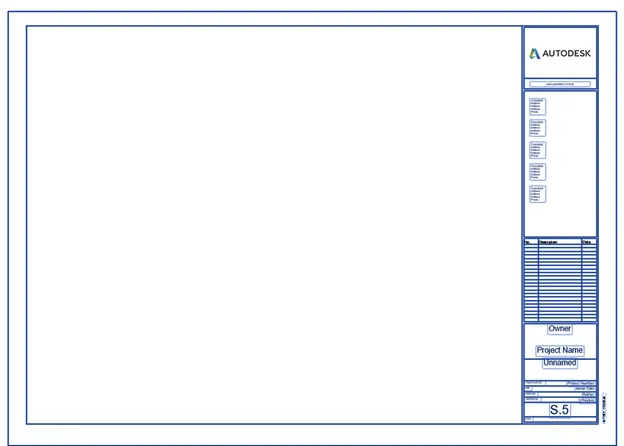
Step2: Now create the sheets in the view tab.
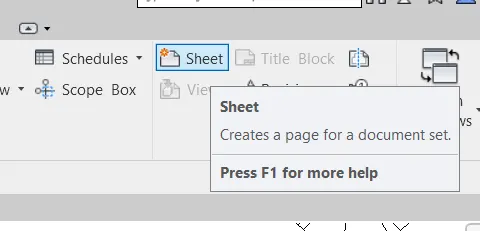
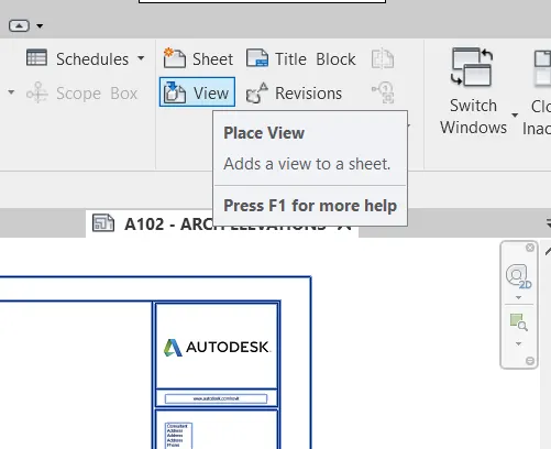
Step3: After creating use the view tool in the view tab to place the views in sheets.
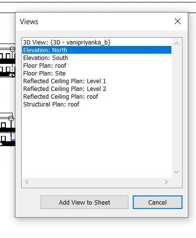
RESULT: By this, we had created the drawing sheets of both architectural and structural models with the help of the view tab.
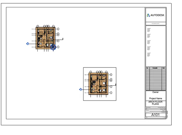
ARCHITECTURAL FLOOR PLANS
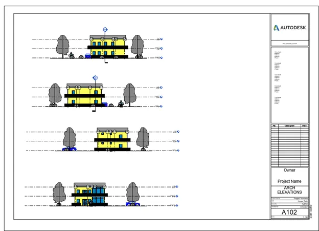
ARCHITECTURAL ELEVATIONS
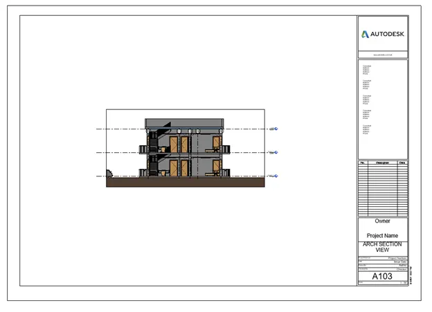
ARCHITECTURAL SECTIONAL VIEW
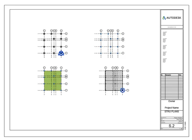
STRUCTURAL FLOOR PLANS WITH ANALYTICAL VIEW
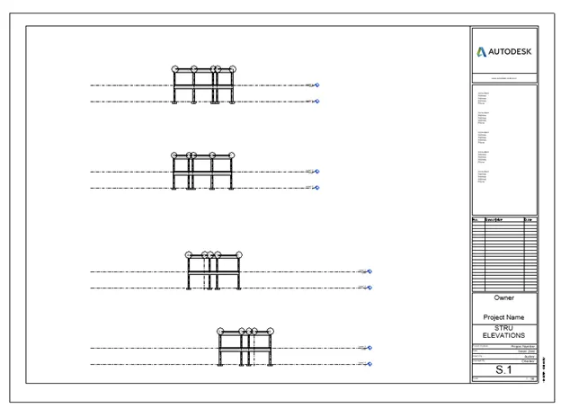
STRUCTURAL ELEVATIONS
6) Using the Rendering settings, render images of the 3D model produced and include the rendered images in the drawing sheets
a. Rendering from interior rooms
b. Rendering from out showing topographic features
c. Rendering through structural framing
AIM: To create the renders for the architectural and structural models.
Tools Used: view tab, camera, render, sheets, view tool.
Procedure:
Step1: Open the architectural and structural models.
Step2: open the view tab and use the camera to create a camera view of a particular view or area.
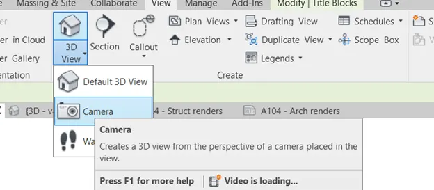
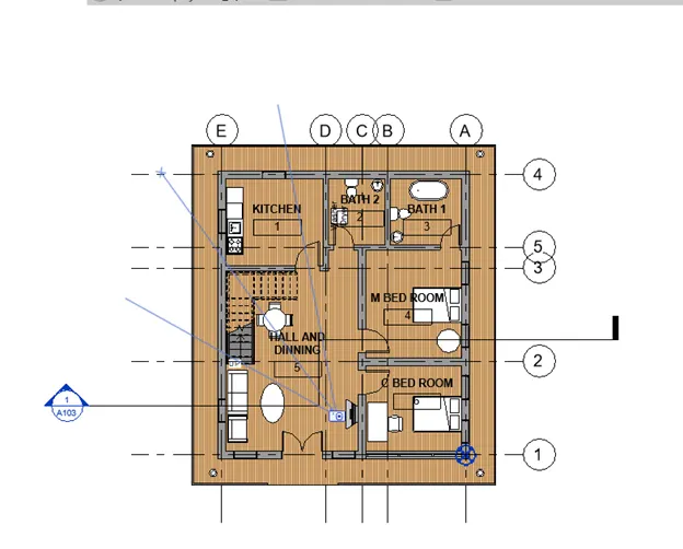
Step3: After creating the camera view open the camera view and use render option in the view tab to create render image.
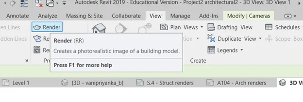
Step4: After that a render settings dialogue box will open and change settings according to requirement and finally click on render to get render image. Here I am using low quality to get render image faster.
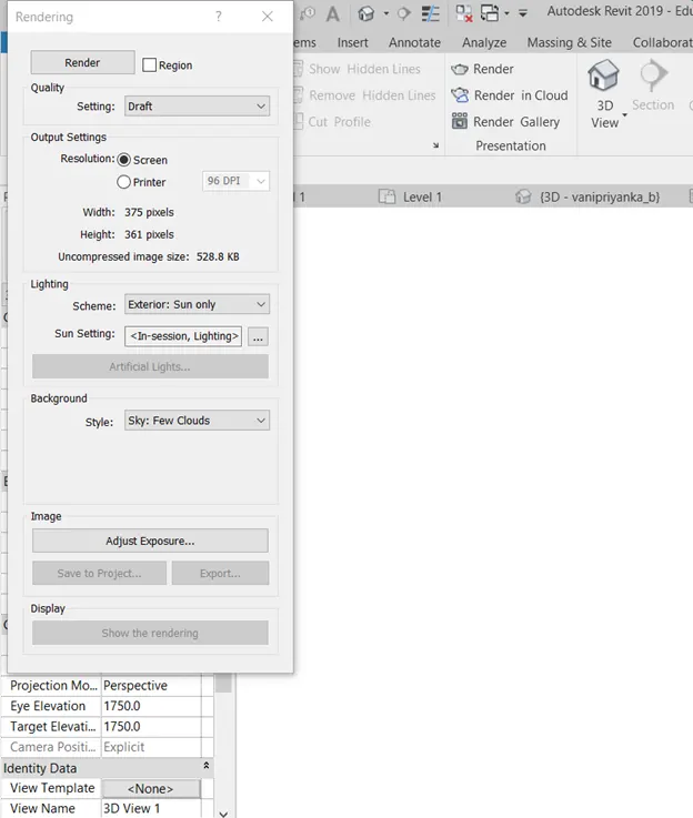
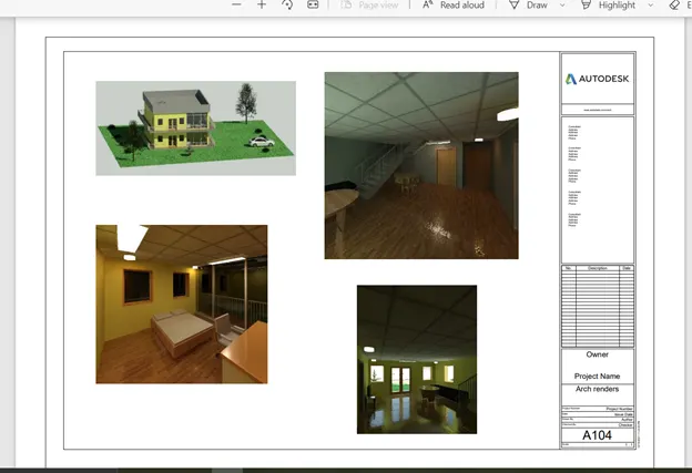
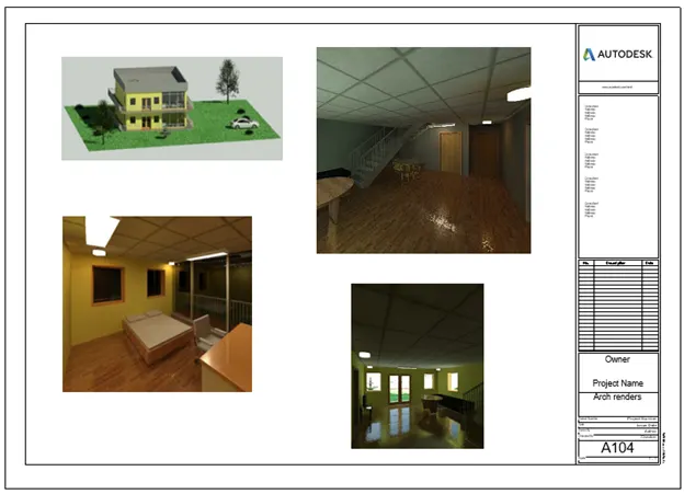
RESULT: The rendered images of both architectural and structural models are shown below:
Exterior sun only setting
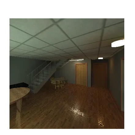
Interior artificial only
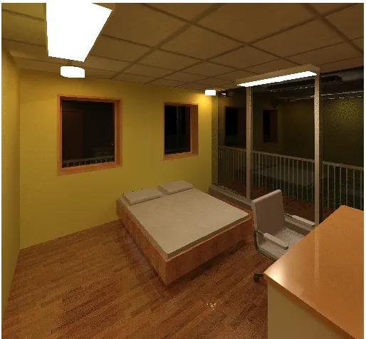
Interior sun only
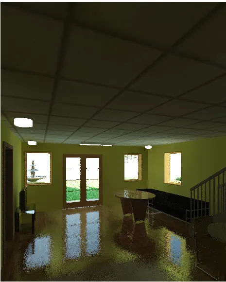
External view showing toposurface
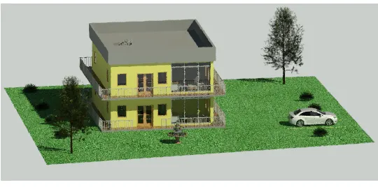
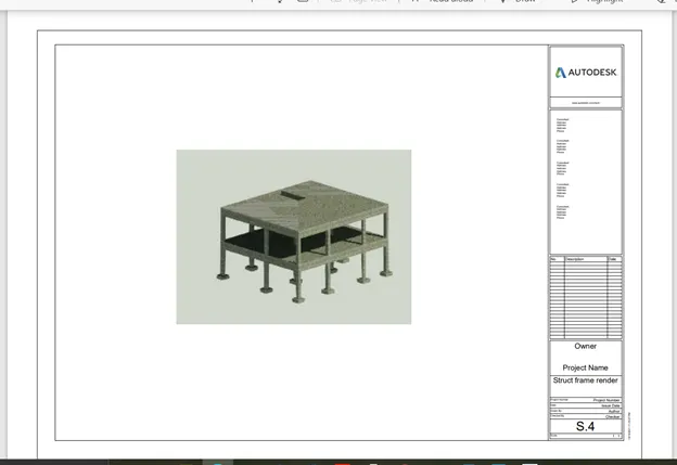
Structural framing
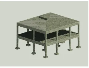
Sheets created including the render views.
7) Print the set of drawing sheets created and submit the drawings from the architecture and structure model
AIM: To print the drawing sheets and submit them for execution.
Tools Used: Print, sheets created, page setup
Procedure:
Step1: Open the architectural and structural models to print the drawings created.
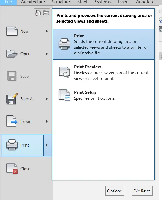
Step2: Go to the file menu to get print options and change the printer settings according to the requirement.
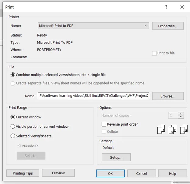
Step3: Here I am printing the drawings in PDF format.
RESULT: By this, we had printed the drawings created in both architectural and structural models and below showing some of the printed drawings: