Creating Architectural and Structural model with 3D rendering using REVIT
1. AIM: Type of structure.
Soln: Office structure:
- Area of 1856m2
- Build up area is 526.03m3
- No. of floors: 5 floors.
2. AIM; To write the geographic and location details for your project modeling.
Soln:
Type of construction : 2
Plot size: 40mx70m
Super Build up area :1856m2 (40mx46.4m).
Open space around the building is not less than 4m.
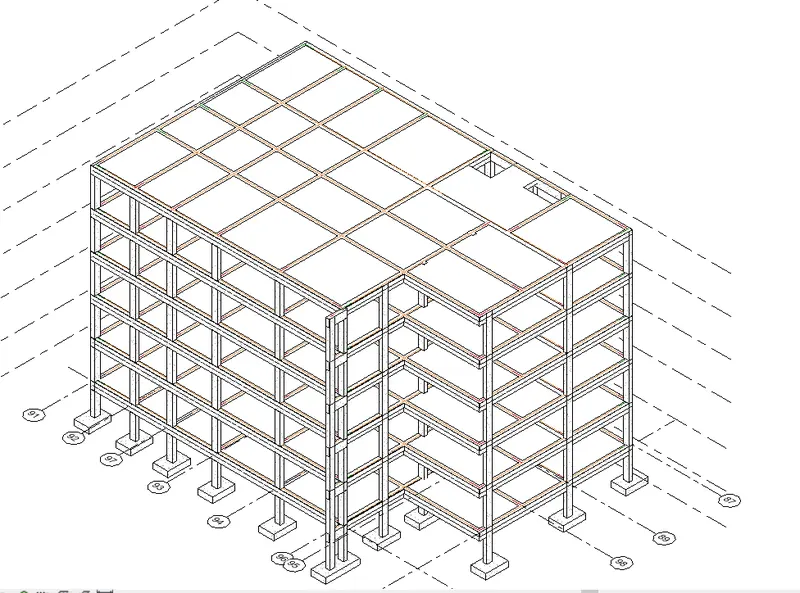
3. AIM: Create a structural model .
a. Foundation – Isolated / Wall/Matt Foundation
b. Columns
c. Beams Connected to Columns
d. Roof Framing/ Truss
e. Floor / Decks
f. Floor Openings for Elevators and Stairs
Soln:
FOUNDATION:
- Create a grid according to the architectural model.
- Set the coordinates.
- Create levels for the following:
- Foundation
- Ground floor
- First floor
- Second floor.
- Third floor
- Fourth floor
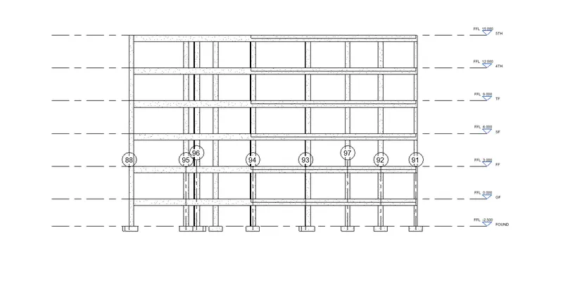
Go to structural tab.
In the foundation tab, select the type and size of footingas per the design.
Place the footing where required.
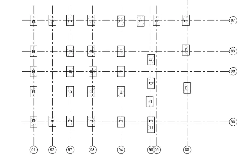
COLUMNS:
Go to structure tab
Choose column tab
Select the size as per the design.
Place the columns as per the design.
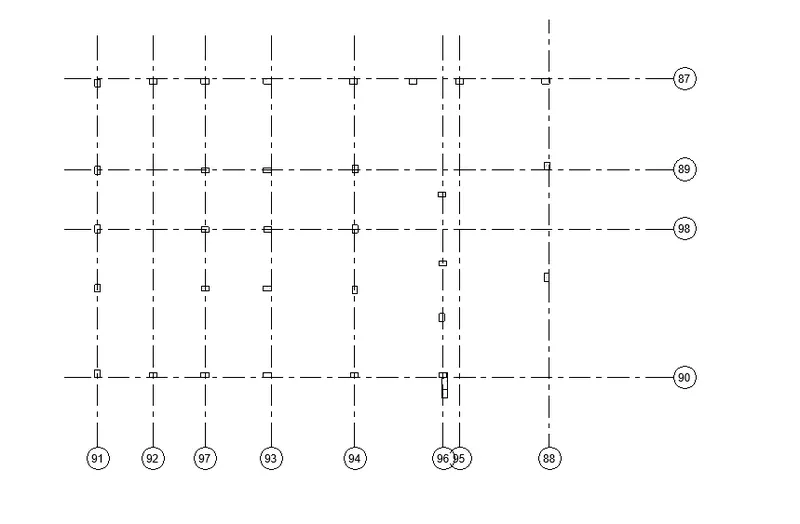
BEAM:
Go to structural tab
Select beam option
Select the size.
Create the beams.
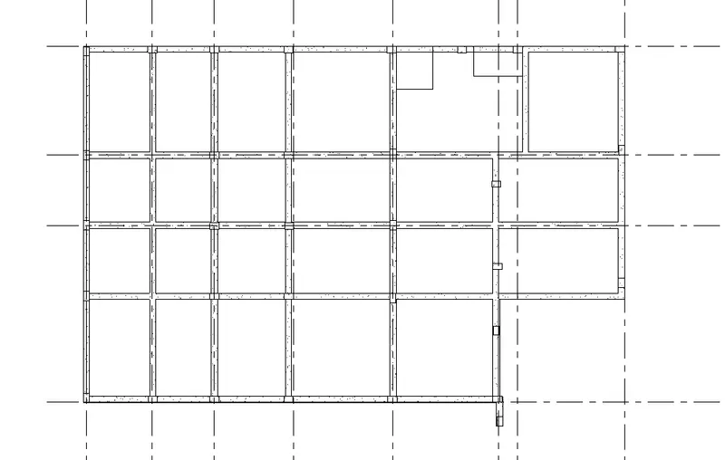
FLOOR:
Go to structural tab
Select type of floor: architectural floor
Draw the boundries
Create openings
Go to shaft
Create the boundaries.
4. AIM: Create architectural model including the following component.
a. Wall Layout with appropriate material and finishing.
- Create Grids.
- Set coordinates
- Select wall tab and type of wall to be used
- Start drawing the outer walls.
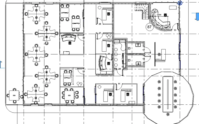
b. Exterior façade with fancy finish
- Select the wall type according to the design
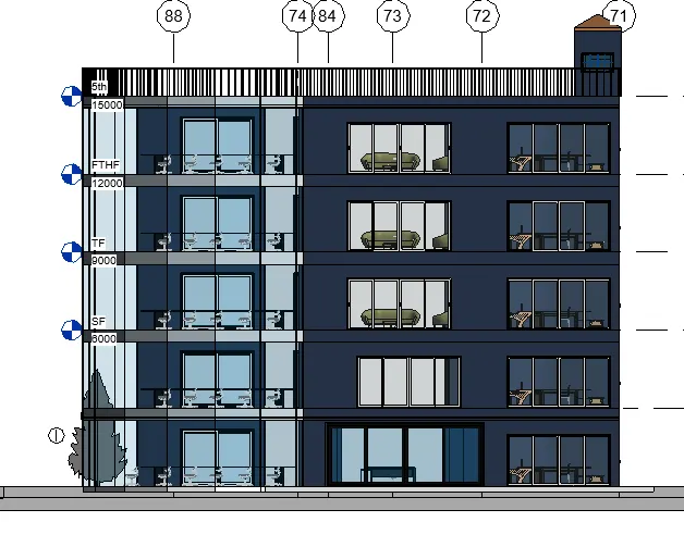
c. Interior partition walls to size rooms
- Select partition walls for the exterior rooms.
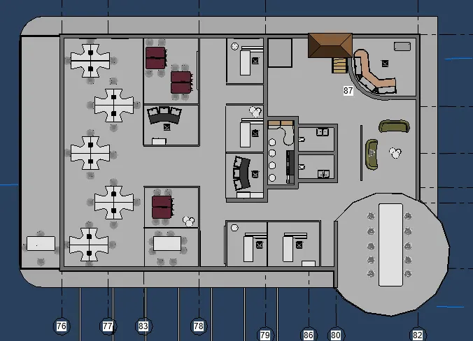
Select curtain walls where required
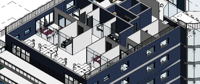
d. Components to add details to a room ( Desk, Chair, Lighting, Plumbing fixtures)
- Select door or window.
- Go to component tab
- Place the componenets as required.
e. Add components such as stairs Elevators
- Check the floor boundaries for the elevator and staircase
- Go to stairs tab
- Select stair type
- Create the stair
- Adjust the bottom level and top level of the stairs.
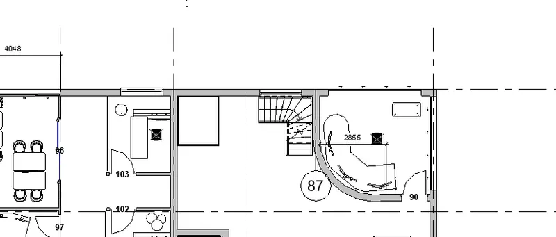
f. Have at-least one side of the building with curtain walls and glass panels
- Select the wall and create a curtain wall as required.
- Glass railings are also placed
g. Include interior and exterior lighting fixtures
- Go to ceiling levels
- Slect components
- Place the lighting as per the dimensions
- For exterior floor lamps are places from the ground level.
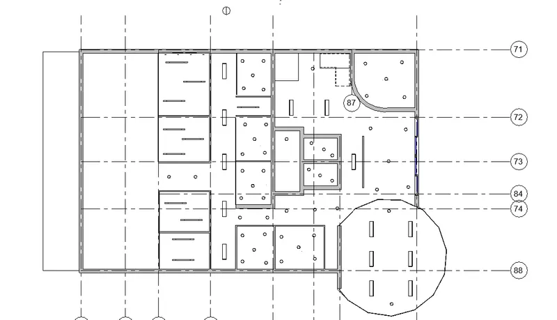
- As shown in figure the lightings are place as required.
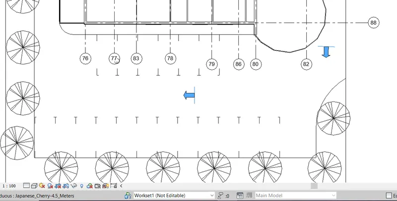
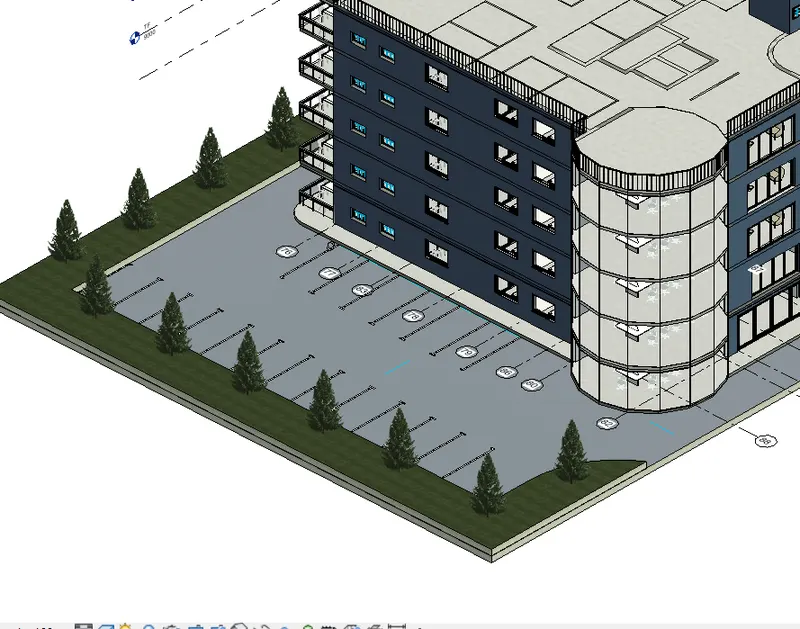
h. Place proper topographic components from outside ( Trees, Parking, Plants) to add details to the model
For parking
- Create the level below the plinth level
- Select the massing& site tab
- Go to topography.
- Select parking componenets
- Place the components with the required dimensions
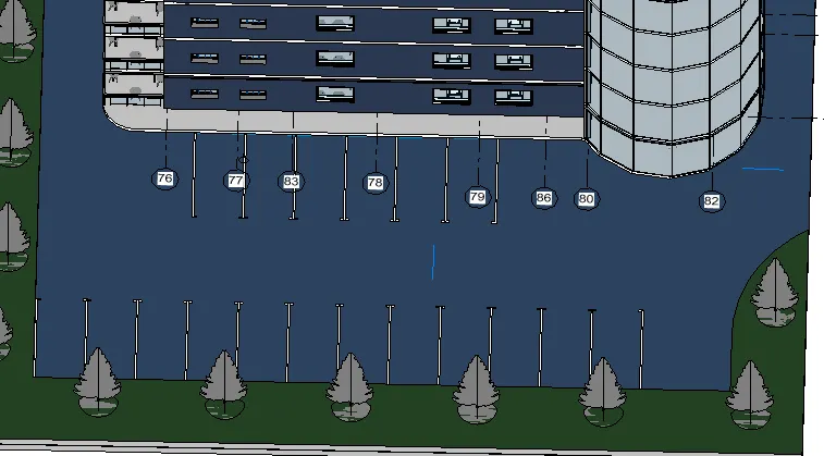
For plants and trees :
- Go to massing and site
- Select topography.
- Select site components.
5. AIM:To provide a set of drawings in an architectural and structural model to list the following details with categories and appropriate sheet templates included
a. Floor Plans with Annotations
b. Elevations
c. Sections
Soln:
a. Floor plans with annotation:
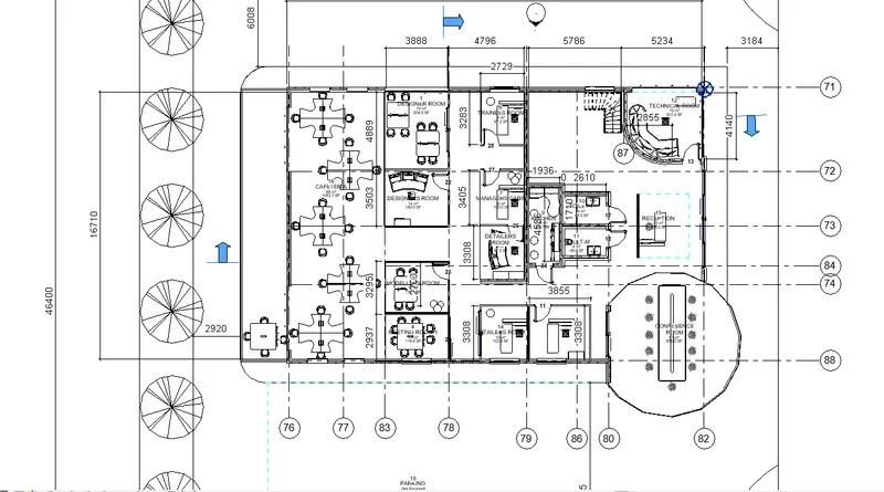
Go to annotation tab
Measure all the rooms.
Select room seperation
Seperate the room and tag the rooms
Change the names
The rooms are named as follows
- Detailers room
- Modellers room
- Designers room.
- Technical controller
- Toilets
- Receptions
- Cafeteria area
- Kitchen
- Managers cabin.
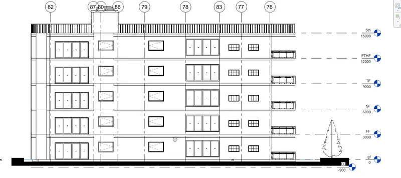
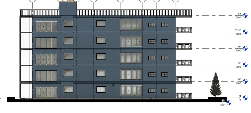
Elevations:
Go to elevation view
Create grids as follows:
- Plinth area :-900mm
- Ground floor:0
- First floor:3000mm
- Second floor:6000mm
- Third floor: 9000mm
- Fourth floor: 1200mm
- Fifth floor:1500mm
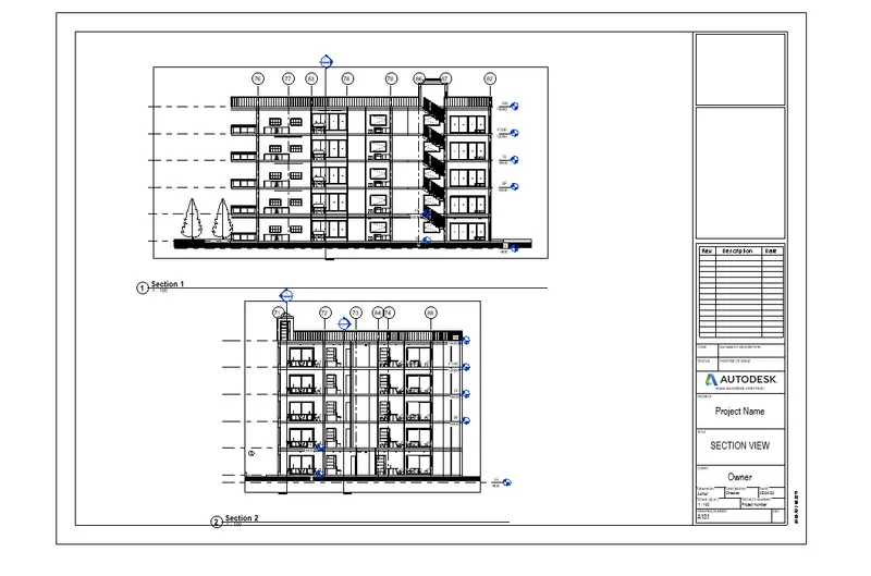
c. Sections:
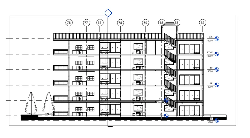
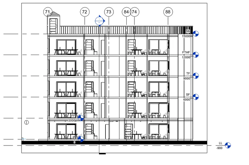
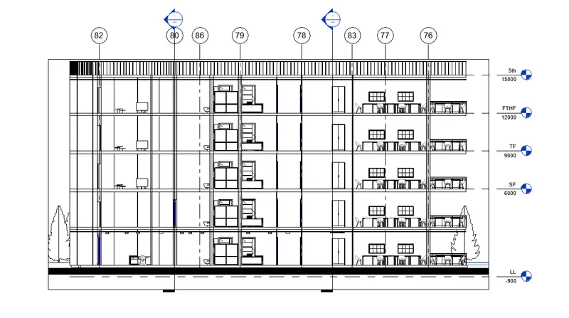
Go to section tab(on top of the screen).
Go to floor plan.
Create the section horizontally, vertically and along the staircase.
Section 1:
Section 2:
Section 3:
Sheet for section :
6. AIM: To render images of the 3D model produced and include the rendered images to the drawing sheets
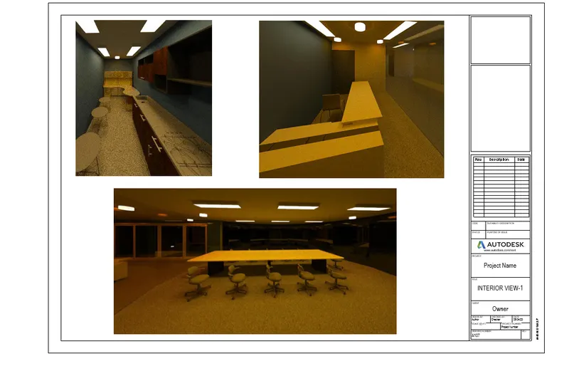
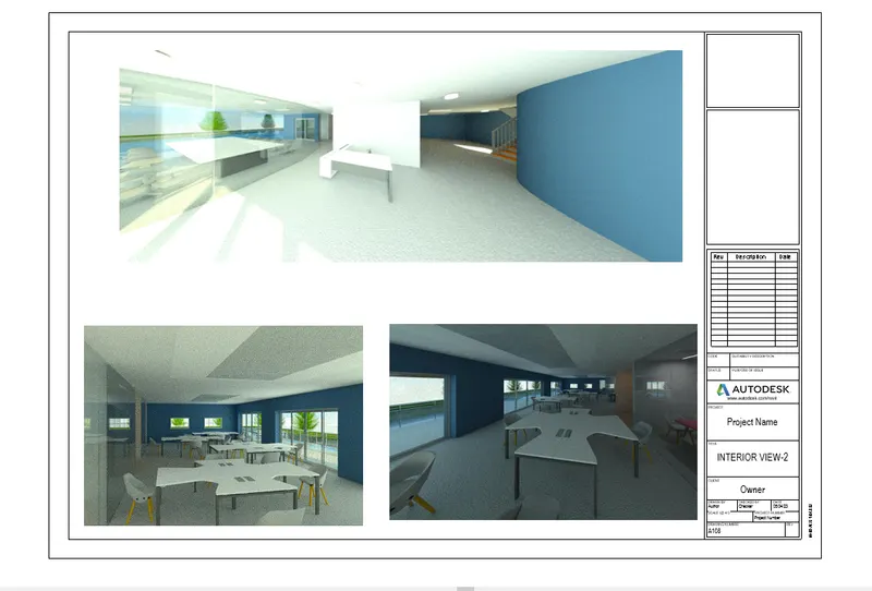
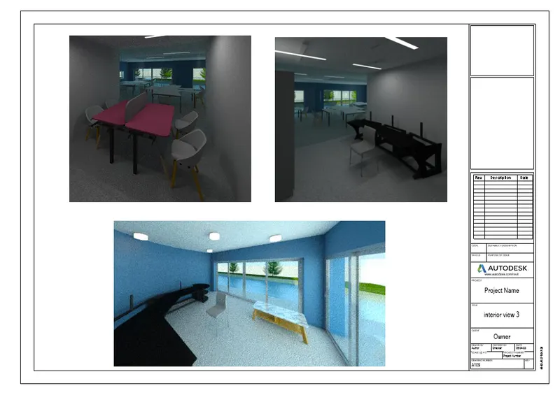
a. Rendering from interior rooms
b. Rendering from out showing topographic features
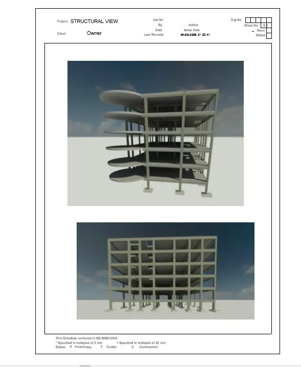
c. Rendering through structural framing
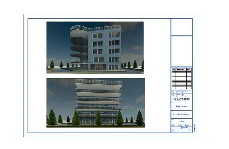
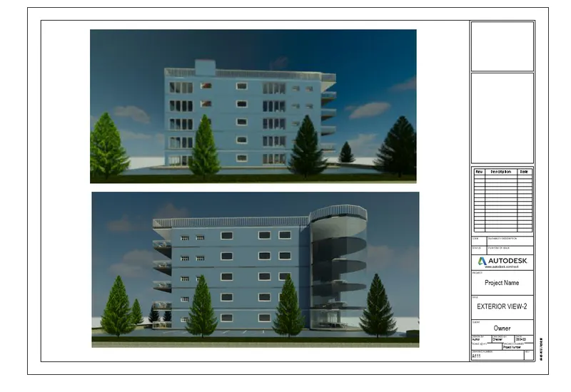
- Soln: Go to view tab.
- Select camera and create a camera view.
- Now go to 3Dviews
- Select render options
- Adjust the quality,exposure, lighting
- Click on render
- Save the image or the image will be display in render properties
- Select sheet option from the view tab
- Select the type of sheet
- Now drag the view from the properties browser.
- Place it .
Render for interior:
b. Rendering from out showing topographic features:
c. Rendering through structural framing
7 AIM: Create a pdf for the set of drawing sheets created from the architecture and structure model
Click on print
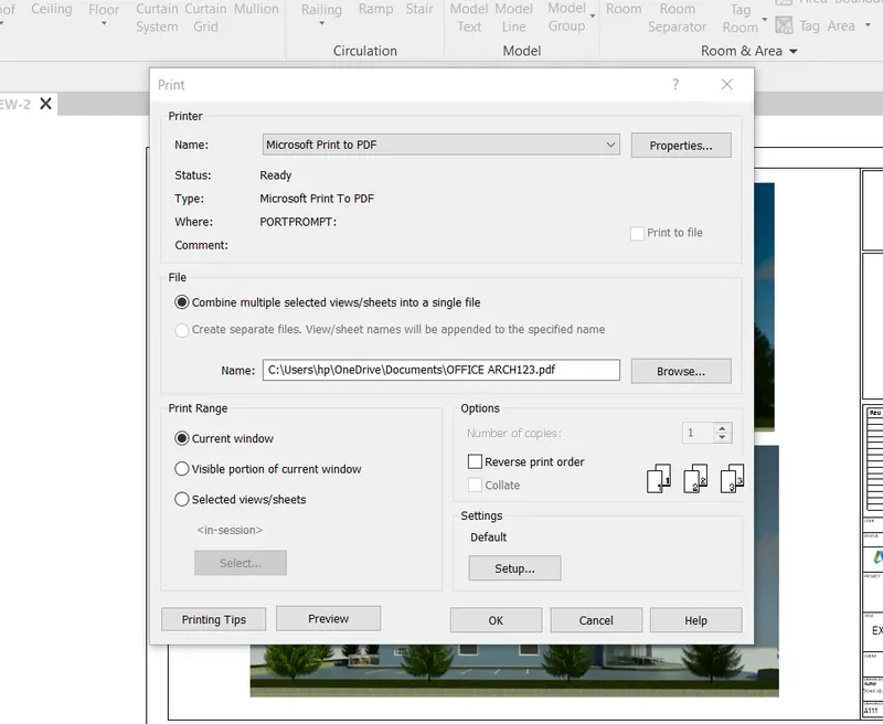
Adjust the file, range and other options
Select printer name as microsoft print to pdf.
Select the destiny for the pdf file
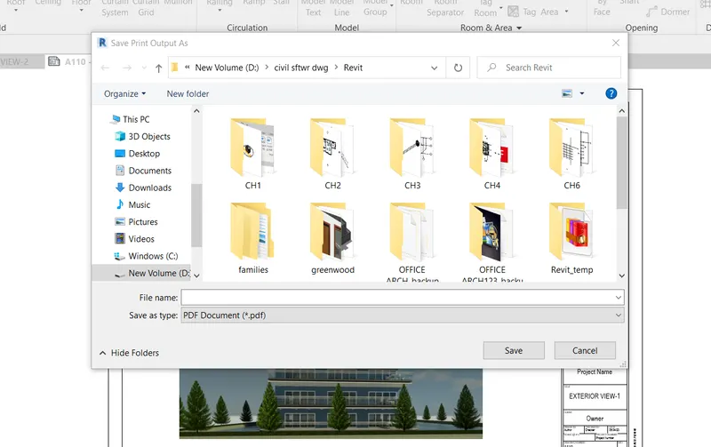
Type the name
click ok