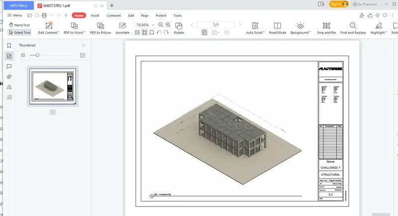
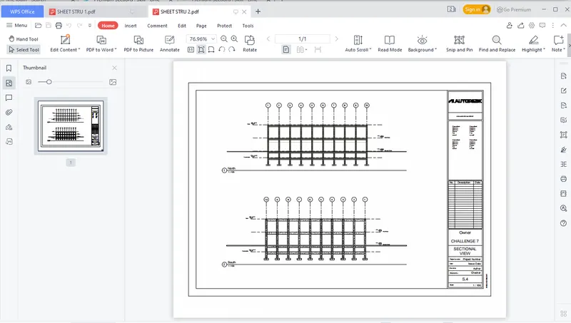
Creating Architectural and Structural model with 3D rendering using REVIT
Creating Architectural and Structural model with 3D rendering using REVIT
1) Aim : Select the type of structure you want to build from one of the three below:
- Multi-Unit Residential Apartment
- Office Buildings
- School
Introduction : Depending upon the type of structure the design consideration of building for the modelling purpose vary. So it is important to clarify the type of structure before starting any project so that it will serve its functionality for which it is being modelled.
Procedure : As per National Building Code th Office/Business Building
- The open space around the building shall not be less than 4.5m.
- The Type of construction as type 2 construction building shall be taken as 2.9
- The width of the Road abutting the building is taken as 9m ( 30')
Result : Taking a G+1 Office building, type of structure is selected as Office building for modelling in the Revit.
2) Aim : Assume reasonable assumptions for geographic and location details for your project modeling. Based on assumptions and type of structure selected identify the modeling requirements from NBC
Introduction : National building code provides the standards which should be followed while designing any type of the model. It provides minimum standards which should be provided for different type of structure for different locations so that it serves its functionality optimistically without violating environmental and safety measures. For office building NBC provides the minimum standards for area, height, thickness of wall etc.
Procedure :
- The office building is planned to be constructed in GURUGRAM.
- Modelling requirements as per NBC-
- Since, my building is an office building, it can be taken as a business building.
- The open space around the building shall not be less than 4.5m.
- Considering the type of construction as type 2 construction , the FAR value for the business building shall be taken as 2.9. and individual floor area is 2000m2
- The width of the road abutting the building is taken as 9m (30').
- The maximum height of the building shall not exceed 1.5 times the width of road abutting plus the front open space. Building will consist of 2 floors each floor having a floor height of 3.6m. Hence, the entire floor height will be 7.4m, which is within the limits prescribed by NBC.
Result : Therefore, location for building is assumed as Gurugram, India, and also based on assumption and type of the structure selected modelling requirements of NBC are identified above.
3) Aim : Using the structural model, include the following components based on the type of structure selected
- Foundation – Isolated / Wall/Matt Foundation
- Columns
- Beams Connected to Columns
- Roof Framing/ Truss
- Floor / Decks
- Floor Openings for Elevators and Stairs
Introduction : The components such as foundation, columns, beams, floors are the structural elements of the model which carry various kinds of loads coming on the structure. Such structural framing elements can be added in the model using the structural template in the Revit software.
Procedure :
1. FOUNDATION
- Open Revit software, select the structural file linked with the architectural template created last week and open it from home page of Revit software.
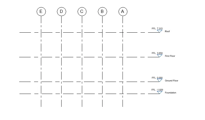
- Go to structure tab, select the level tool from datum panel, select pick line tool from draw panel and add the levels by specifying offset distance at required position as shown below
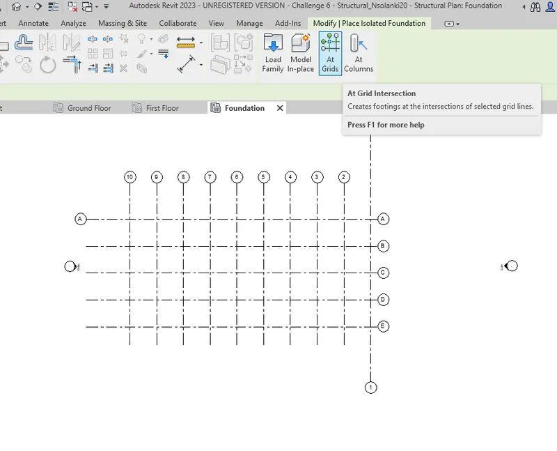
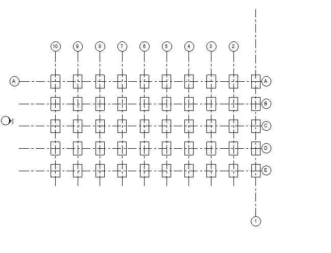
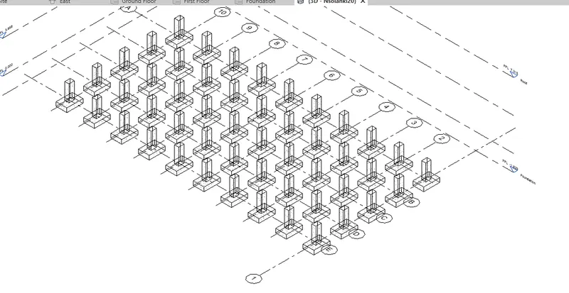
- Go to site plan view, select isolated footing from foundation panel of structure tab, select at grids option from place isolated foundation tab and select the grids by dragging the mouse and select finish from multiple
2. COLUMN
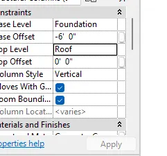
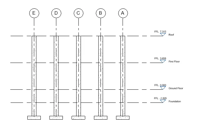
- For creating the columns, go to column tool from structure tab, select the column type as concrete rectangular column of size 450x600 mm and change the depth of column as -6’ from properties window.
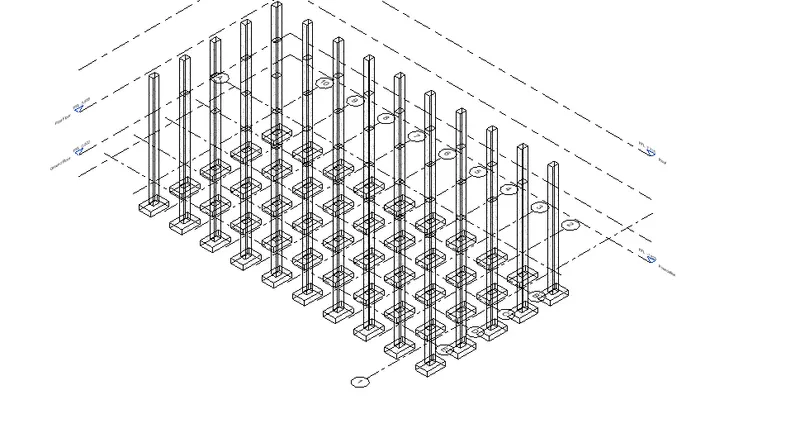
- Again, select column and create column at ground floor by selecting height option from modify toolbar of column and height up to first floor as shown below.
3. BEAM
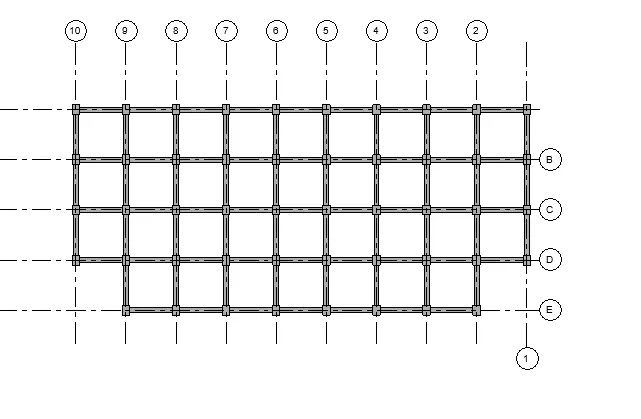
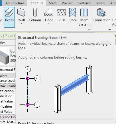
- Go to structure tab, select beam tool, select concrete beam from property window, select on grids option from place beam tab, select the grids by dragging with mouse and select finish from multiple panel.
- To create the beams and column at the first ang ground floor, go to ground floor plan, select all componenets by draging with the mouse, select filter tool, and select the stuctural column, structural framing from filter dialog box
- Select the Front corners of plan, select filter tool from multi-select tab, uncheck grid option and delete key to delete it.
- Similarly delete the foundation from FRONT CORNERS
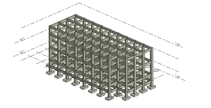
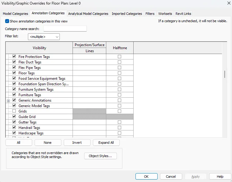
- To hide analytical lines, type VG command, uncheck all analytical model category visibilities from dialog box,
select apply.
- .
4. FLOOR
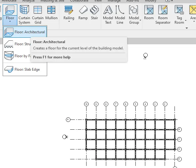
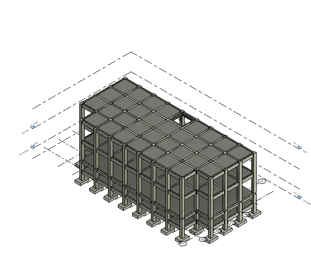
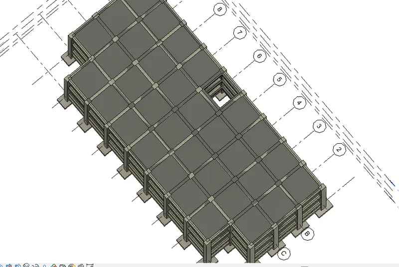
- To draw the floors, go to site floor plan, select the floor tool from structure tab, select rectangle tool from draw panel and draw the roof as shown below by changing the height offset of roof as 3”. Similarly create the roof floor as shown below
5. FLOOR OPENING FOR LIFT/STAIRS
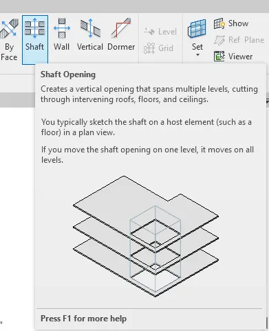
- For creating the shaft opening go to shaft tool from structure tab, select rectangle tool from draw panel and draw the shaft as shown below.
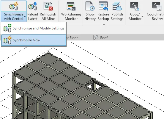
- Go to synchronize with central option from top toolbar and select ok.
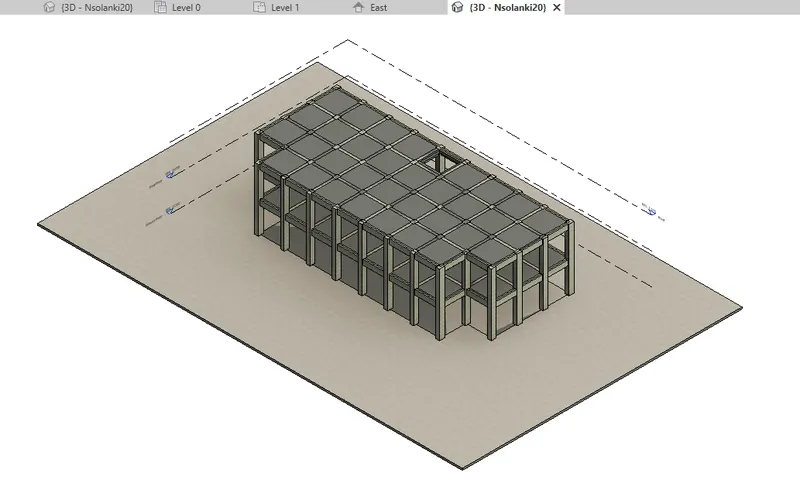
Result : Therefore, all the structural components such as footing or foundation, columns, beams, floors and stairs are created in structural and architectural file as shown below
4) Aim : Using the architectural model, include the following components based on the type of structure selected
- Wall Layout with appropriate material and finishing
- Exterior façade with fancy finish
- Interior partition walls to size rooms
- Components to add details to a room ( Desk, Chair, Lighting, Plumbing fixtures)
- Add components such as stairs Elevators
- Have at-least one side of the building with curtain walls and glass panels
- Include interior and exterior lighting fixtures
- Place proper topographic components from outside ( Trees, Parking, Plants) to add details to the model
Introduction:
- Revit is a BIM software where we can add the minor details to make the model more realistic to utilize or make more efficient space management without making any compromises in the future.
- Architectural elements such as walls, doors, windows etc., can be added in the model using the architectural template. Such details may include desk, chairs, lighting etc.
- In Revit we can also add the topographical features which can be helpful to estimate the excavation or cutting cost even before starting the project.
Procedure :
Wall Layout with appropriate material and finishing
- Open the architectural file from home page of Revit software to add the architectural components.
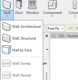
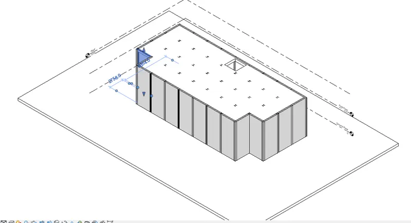
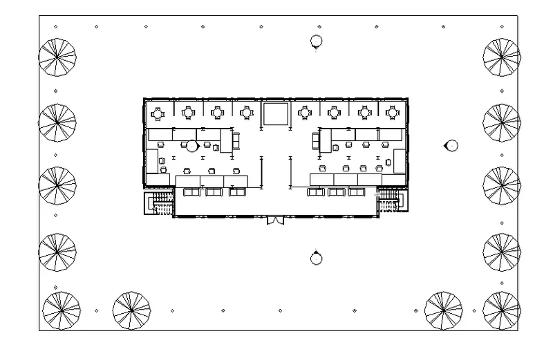
- Select the walls tool from architecture tab, select wall type generic 12” from property window and draw the walls at required position as shown below.
Exterior façade with fancy finish
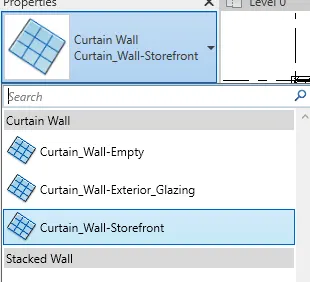
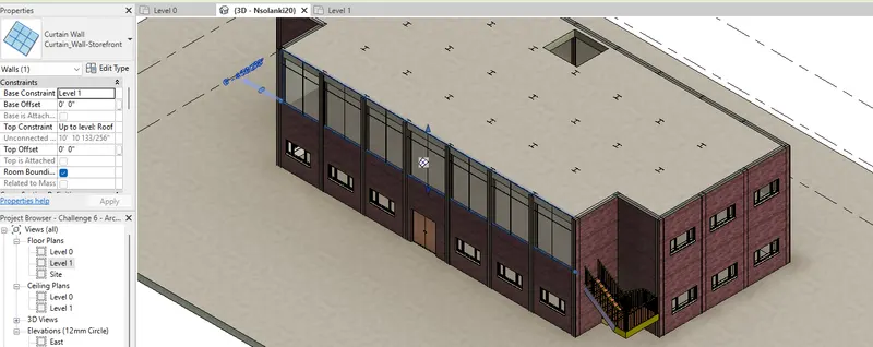
- For adding the curtain system, select the front wall which is required to make as curtain wall, select drop down of basic wall type, and change the wall type to storefront as shown below.
Interior partition walls to size rooms
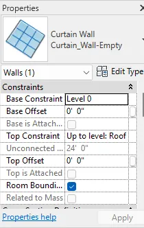
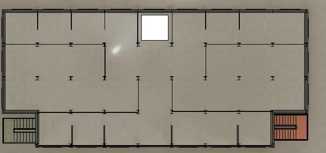
- Now for partetion/interior wall select the curtain wall so as to seperate the workspace area and set the Top constrain up to roof level, so that first floor also follows the same seperation
Components to add details to a room ( Desk, Chair, Lighting, Plumbing fixtures)
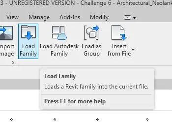
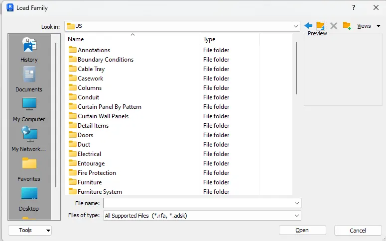
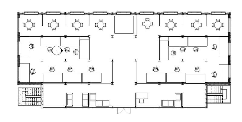
- For adding the components such as desk, go to architecture tab, select the component tool from build panel, select load family option and load the desk and add it in the model at required position as shown below
- Similarly add the component in the first floor plan as shown below
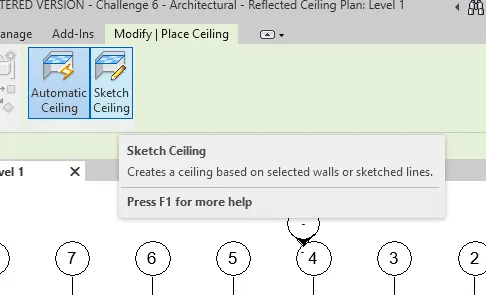
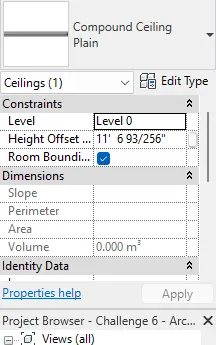
- Now make a ceiling for both the floors , select the celling then go to sketch ceiling and draw the outter boundary of the building.
- Select the wall by using the filter tool, go to edit type from properties window, duplicate wall type and select the wall material as brick common and select ok as shown below
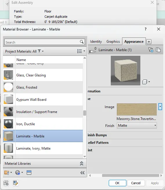
- For floor material Duplicate the material and ad the desired image in the apperance
- Go to architecture tab, select door tool from build panel, select load family from mode panel of place door tab and place the doors at required position as shown below.
- Similarly add the windows to all the rooms at the required position as shown below.
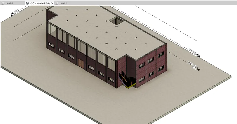
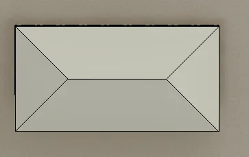
- For adding the roof, go to architecture tab, select the roof tool from build panel, select roof by footprint, select pick line or line option and draw the roof on the first floor plan by specifying offset distance as 24’ from the level as shown below.
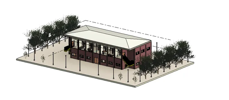
Result : Therefore, wall layout with appropriate material and finishing, interior partition walls, components adding details, stairs, lighting, stairs, and topographical components are added in the model as shown below
5) Aim : Provide a set of drawings in an architectural and structural model to list the following details with categories and appropriate sheet templates included
- Floor Plans with Annotations
- Elevations
- Sections
Introduction : To communicate with the help of drawing with the workers who actually execute the construction of the project on site the annotations such as dimensions are provided and rooms are tagged with their respective names so that it will be executed as per the designed plan. Dimensions and room tag add details to the project. In Revit dimensions of lines are measured with help of the aligned or horizontal tool of the annotate tab.
Procedure :
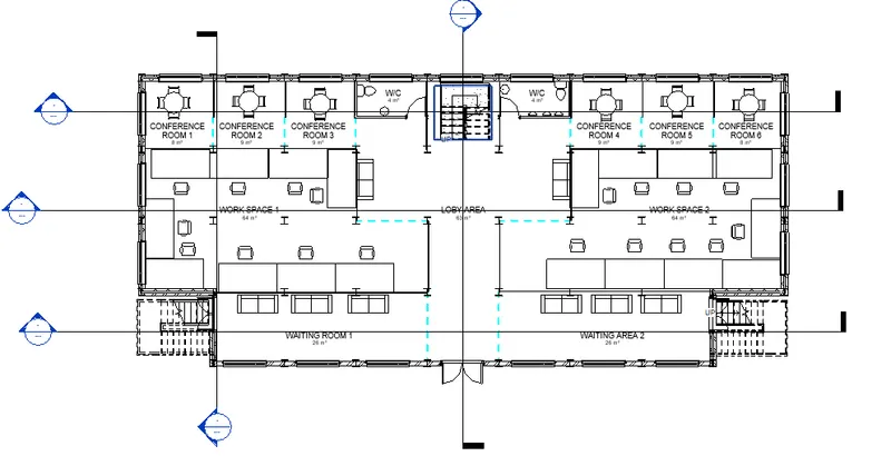
- Open the architectural template file to give annotation i.e., dimensions to the plan, go to annotation tab, select linear or aligned tool and give dimensions to the plan view as shown below.
- Similarly go to room tool from room and area panel of architecture tab, and give room tags to each room as shown below.

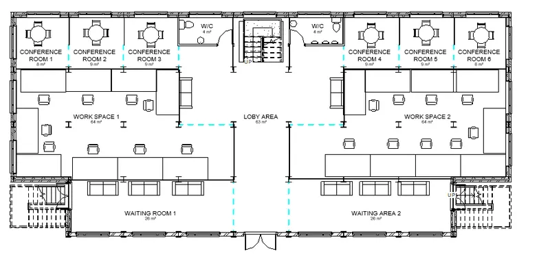
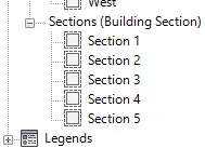
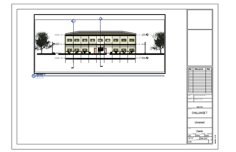
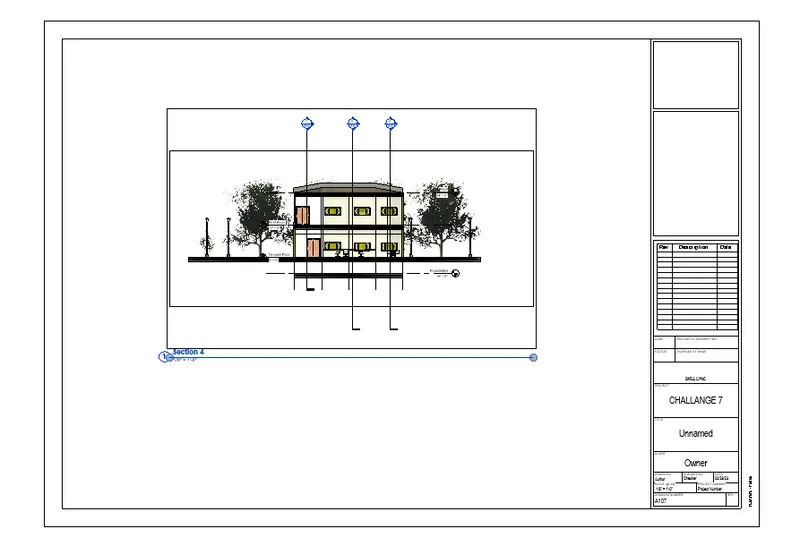
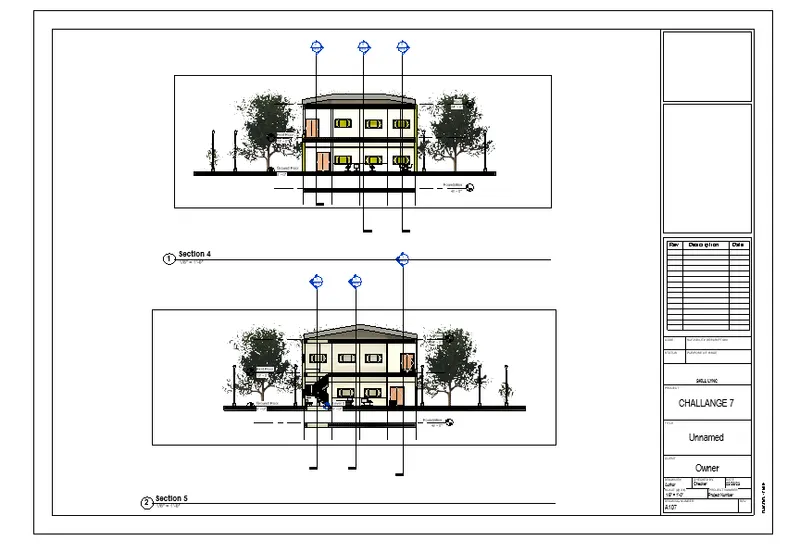
- For creating the section view, go to view tab, select section tool from create panel and draw the section at the required position as shown below

- For creating the floor plan, go to view tab, select plan views tool from create panel, select floor plan and select ok.
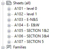
- For creating the sheet, go to view tab, select the sheet tool from sheet composition panel, it will open the new sheet dialog box.

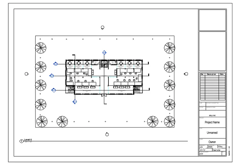
- Select the sheet paper size as E1 30x42 Horizontal and select ok from dialog box, it will open the created sheet template as shown below.
- For adding the floor plans in the view, select the view from project browser and drag the view into sheet as shown below.
- Adjust the scale of view as per requirement using properties window.
- Similarly insert the first floor plan, site plan and roof plan of school building by dragging the view from project browser after creating the sheet as shown below.
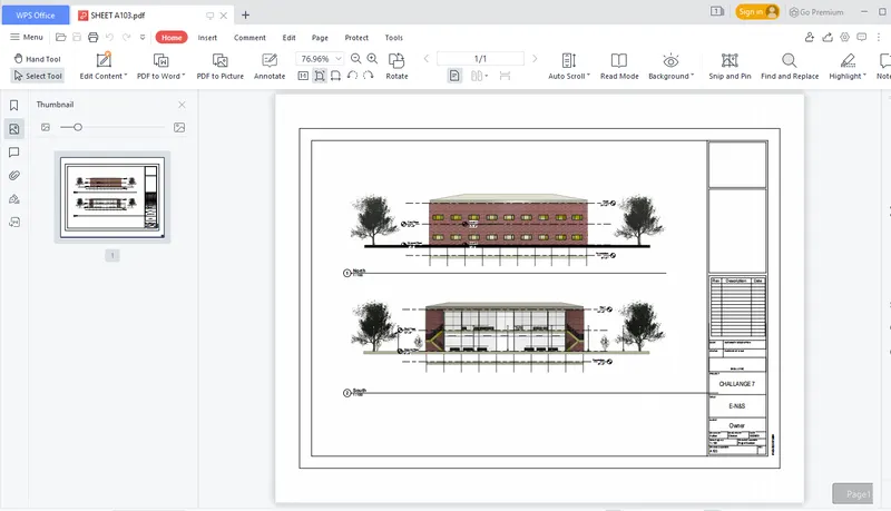
- For adding elevation vieWs in the sheet, select elevation views from project browser and drag the views into the sheet after creating new sheet using sheet tool of view tab.
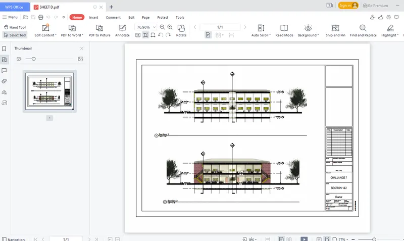
- Similarly insert the section views into new sheet by dragging the views from the project browser as shown below by adjusting the scale of the view using properties window so that the view fits inside the sheet
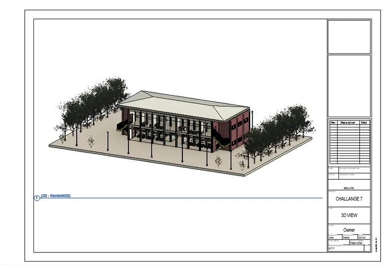
Result : Therefore, set of drawing with structural and architectural elements in the model is created as shown below. Architectural model sheets
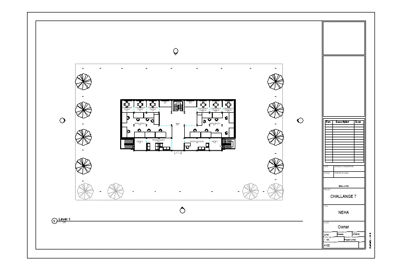
- Floor Plans with Annotations
SHEET FOR LEVEL 0
SHEET FOR LEVEL 1
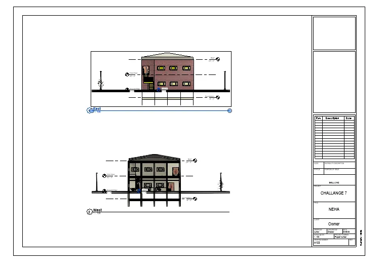
 2. Elevations
ELEVATION EAST AND WEST
ELEVATION NORTH AND SOUTH 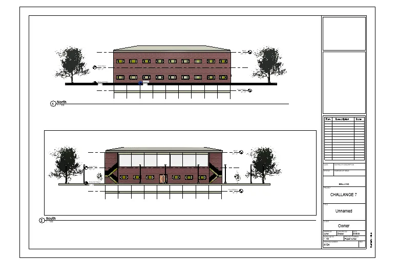
3. Sections
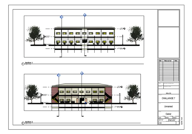
6) Aim : Using the Rendering settings, Render images of the 3D model produced and include the rendered images to the drawing sheets
- Rendering from interior rooms
- Rendering from out showing topographic features
- Rendering through structural framing
Introduction : Revit is BIM software where we can create the 3D views and using the rendering tool of the view tab more realistic views can be obtained. In Revit we can add detailed component due to which it is possible to manage or utilize the space even before starting the construction work in the field without making any compromising any pre planed model components positions.
Procedure :
- Open the architectural template file.
- Go to view tab, select the 3D view tool from create panel and select the camera option and place the camera at the required position to get the 3D camera view.
- The 3D camera view is displayed.
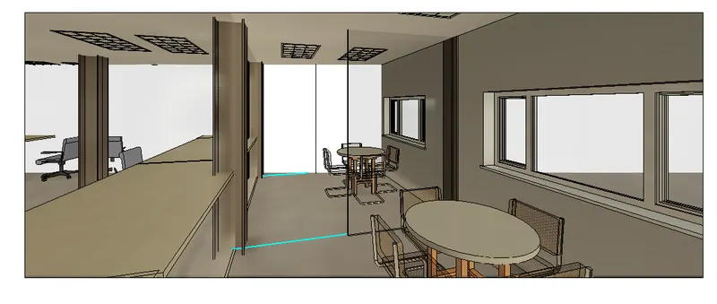
- Go to render tool from presentation panel it will open the rendering dialog box.
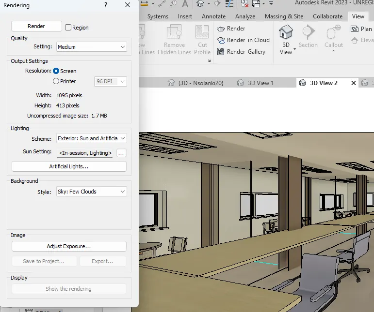
- Select the required resolution as screen or printer, scheme as interior sun and artificial and click on the render option from rendering dialog box.
- It will start rendering the progress of rendering is shown on the screen
- Then adjust the exposure of the image using adjust exposure dialog box to get required exposure.
- The rendered view is shown below
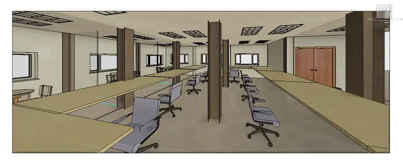
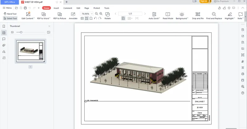
- Rendered overall view of building using best quality setting is shown below.
- For creating the sheet, go to view tab, select sheet tool from sheet composition panel and select the sheet size from new sheet dialog box and select ok.
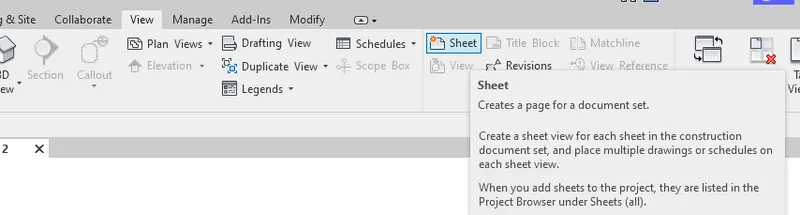
- Edit the sheet parameters and rename the sheet as per requirement.
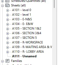
- Select the view from project browser window and drag the view into the sheet and locate it as per required position.
- Adjust the view of the image by double clicking the view or using the scale option from properties window as shown below.
- The created sheets are shown below.
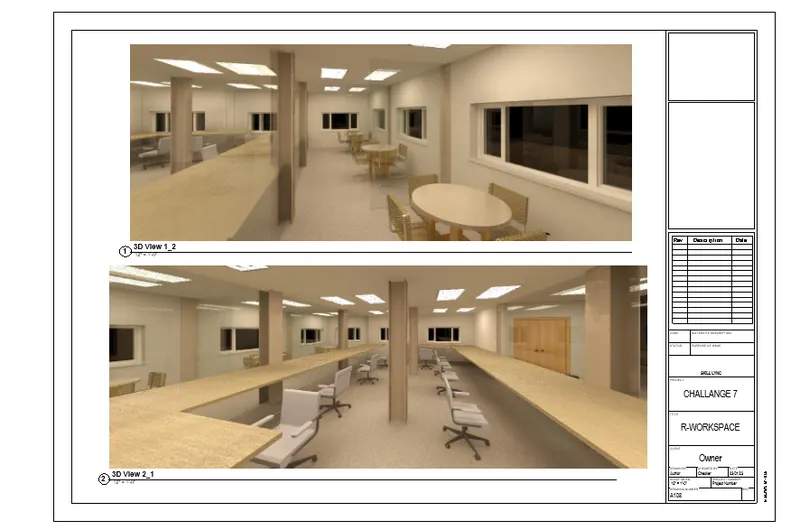
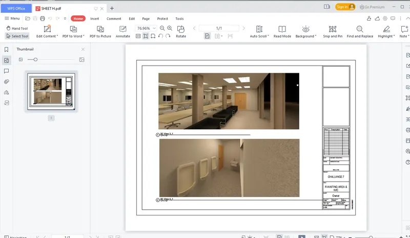
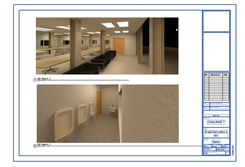
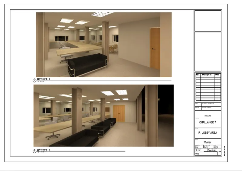
Result : Therefore, using rendering settings the views created in the model are rendered and added into the drawing sheet. Sheets including Rendering from interior room views are as follows.
SHEET A108- R-WORKSPACE AREA
SHEET 109 - R-WAITING AREA & W/C
SHEET A110 - R- LOBBY AREA
7) Aim : Print the set of drawing sheets created and submit the drawings from the architecture and structure model
Introduction : When we model the building in the Revit software it will be saved as .rvt file. For printing the file we have to convert the file into printable format such as pdf. By pressing control and P key we can set the required page layout including the size of the paper etc and convert the file into pdf format.
Procedure :
- Open the Revit software, and click on the architectural template file to open the file from home page of the Revit software.
- Double click on the created architectural sheet from project browser window of the Revit software, to open the view.
- For printing type control + P key it will open the print dialog box.
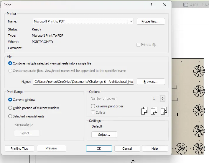
- Select the name as Microsoft print to PDF and choose the page setup option.
- In page setup dialog box, choose the required page setup settings and select ok
- By selecting ok it will again open the print dialog box using which we can see the preview of the printing sheet the select close. Then select ok from print dialog box, choose the destination folder and save the file by giving it the proper name.
- Sheet are created with name Sheet A101 as pdf as shown below.
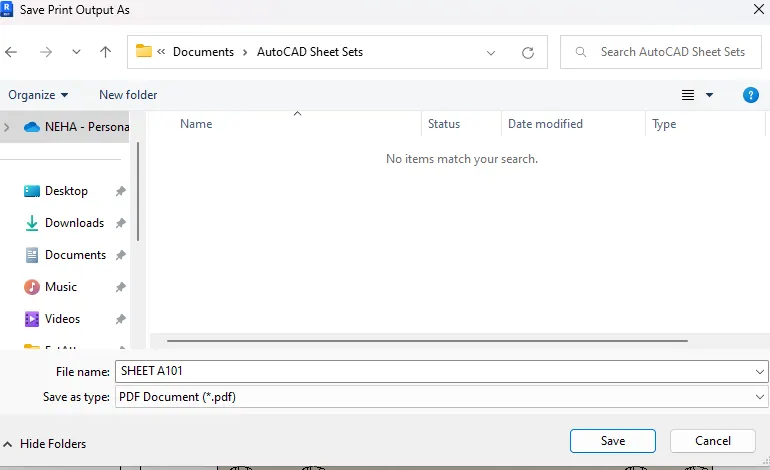
- Similarly follow the similar procedure for printing all other sheets by converting them into pdf format.
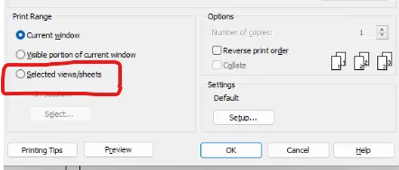
- Another way is to select the number of Sheets to print at once
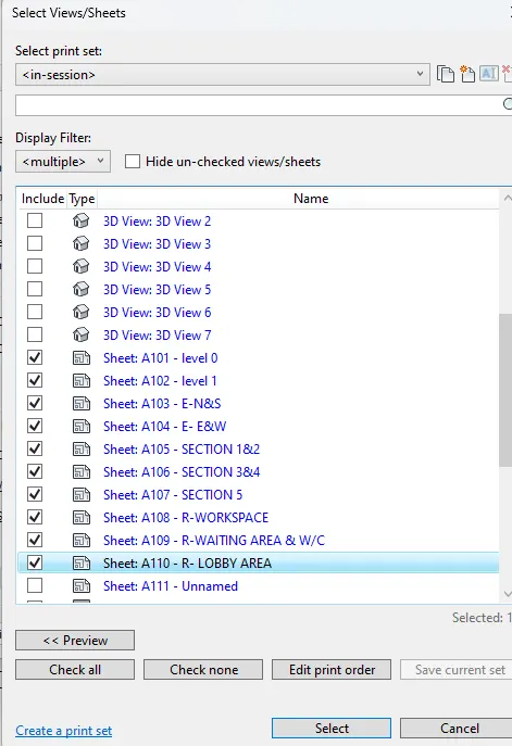
Result : Therefore, created drawing sheets are printed by converting them into the pdf format from architectural and structural model using control + P key. Printed sheets of the architectural model is shown below.