Creating Architectural and Structural model with 3D rendering using REVIT
1) Select the type of structure you want to build from one of the three below:
a. Multi-Unit Residential Apartment
b. Office Buildings
c. School
Multi-unit residential apartment
2) Assume reasonable assumptions for geographic and location details for your project modeling. Based on assumptions and type of structure selected identify the modeling requirements from NBC
AIM: To identify the modeling requirement from NBC
INTRODUCTION:Building codes are a set of ordinances or regulations and associated standards intended to regulate aspects of the design, construction, materials, alteration and occupancy of structures which are necessary to ensure human safety and welfare, including resistance to collapse and damage. The National Building Code of India is a comprehensive building code, providing the guidelines for regulating building construction across the country.
PROCEDURE:As above mentioned by the building comes under the residential category .The project is in plain area in a city. Road width in front of the proposed site is 70ft.
- The height, area and safety measures will follow the rules and regulations of NBC
- The height of my project is 42' and the road width is70'
- Height of the building should not exceed 1.5 times the width of the road width
- The building height is not exceeding so its suitable for construction
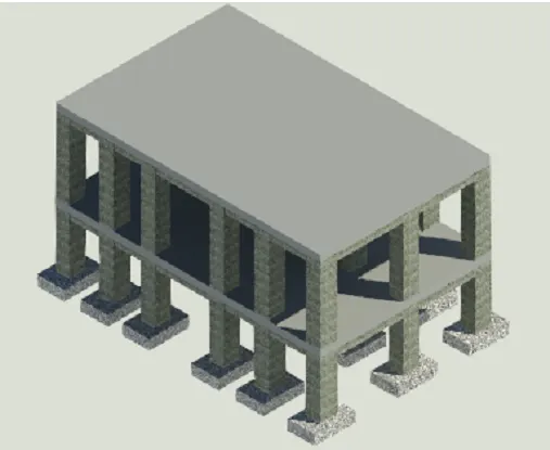
3) Using the structural model, include the following components based on the type of structure selected
a. Foundation – Isolated / Wall/Matt Foundation
b. Columns
c. Beams Connected to Columns
d. Roof Framing/ Truss
e. Floor / Decks
f. Floor Openings for Elevators and Stairs
AIM: By using the structural model, include the following components based on the type of structure like foundation, columns, beams, roof framing/truss, floor, elevators, stairs
INTRODUCTION:
- A set of standard that are uniform to all structures- The building codes become law of particular jurisdiction when formally enacted by appropriate governmental or private authority as we follow the standard codes of building in software it gives the drawing as per the specification in the code book which are ready for construction and camn be followed by vendor.
- It protects the construction safety- All types of buildings have different purposes so they are of different requirements. the habitatable area have a standards but warehouse have other set of standards for the safety
- Modern construction methods- Modern construction methods are economic, efficient and it is very helpful for the time saving
- Provides building standards- Building codes provide the minimum standards for safety, health, and general welfare including structural integrity, mechanical integrity, fire prevention and control and energy conservation. It ensure the economic wellbeing of the community by reducing potential spread of fire and diseases.
COMMANDS USED: Architectural template, Structural template, Grids, Columns, Beams, Foundation, Stair, Shaft, floors
PROCEDURE:
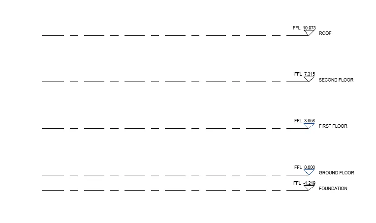
- Open the architectural template in Revit software and save it as residential.arc.001
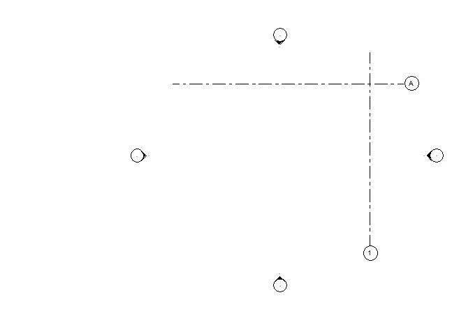
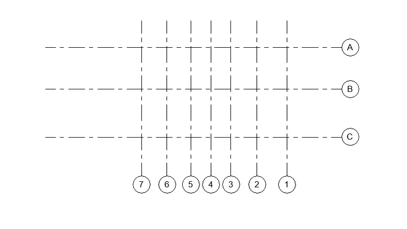
- Draw the grid lines and specify coordinates as 0'0" for both horizontal and vertical grid lines
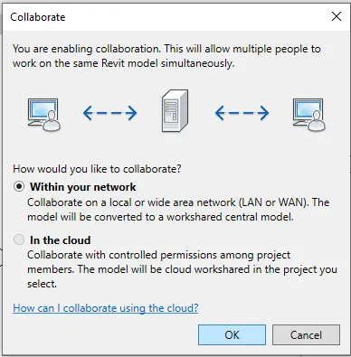
- Click collaborate and save the project
- Similarly do the same procedure with a structural template
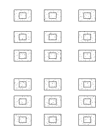
- From structure tab select the isolated footing
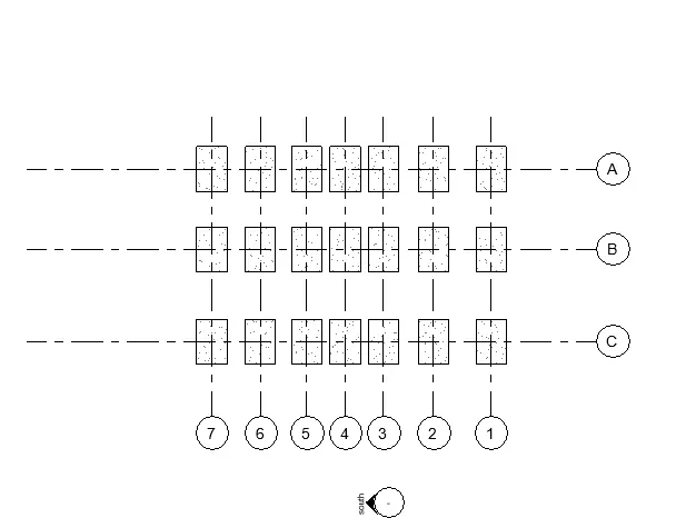
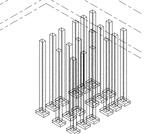
- From structural tab select the column and draw the column with respect to grid
- From structural tab create the beam
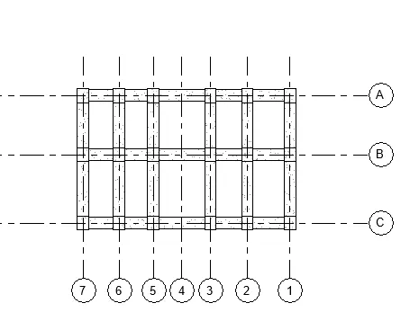
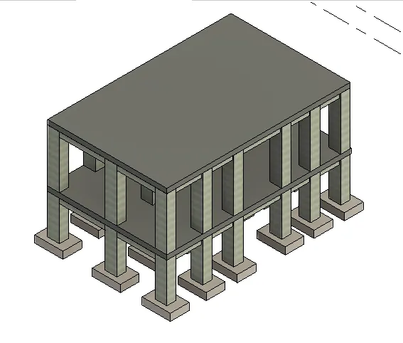
RESULT: Created the structural elements in the structural template
4) Using the architectural model, include the following components based on the type of structure selected
a. Wall Layout with appropriate material and finishing
b. Exterior façade with fancy finish
c. Interior partition walls to size rooms
d. Components to add details to a room ( Desk, Chair, Lighting, Plumbing fixtures)
e. Add components such as stairs Elevators
f. Have at-least one side of the building with curtain walls and glass panels
g. Include interior and exterior lighting fixtures
h. Place proper topographic components from outside ( Trees, Parking, Plants) to add details to the model
AIM: By using the arechitectural model, based on the type of structure selected include the architectural components
INTRODUCTION:
Create views on a project template before you start building the model to streamline the project documentation proess.When creating a project template can include sheets in the template. Start with a blank project file and create the standard views and levels that each project should include. Leave the views empty, but assign standard names to them. To create the standard set of construction documents create sheets using desired title blocks
An elevation is a view of a building seen from one side. It is used to describe the external appearance of a building. Each elevation is labelled in relation to the compass direction it facesSectional views reveal hidden details in the drawing. These views assume that a cutting plane has removed portions of the object represented by the drawing, displaying the appropriate section of the interior. The sectional views are used in engineering drawings and architectural drawings.
PROCEDURE:
- With the same grids drawn in the previous plan draw a wall along the boundary
-
Draw the interior partitions and place the required furniture and components in the plan and change the view to 3d
-
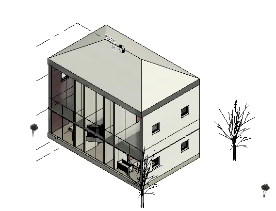
Change the front walls of the building with curtain walls or glazed panel as shown in figure and copy the entire figure and place it to the first floor
- Draw the roof by making a rectangle along all the sides of second floor
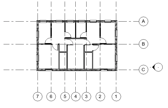
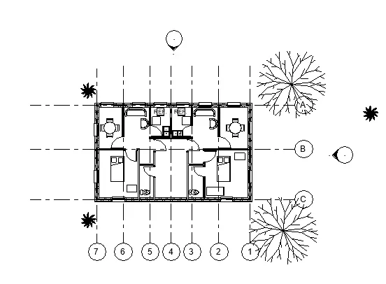
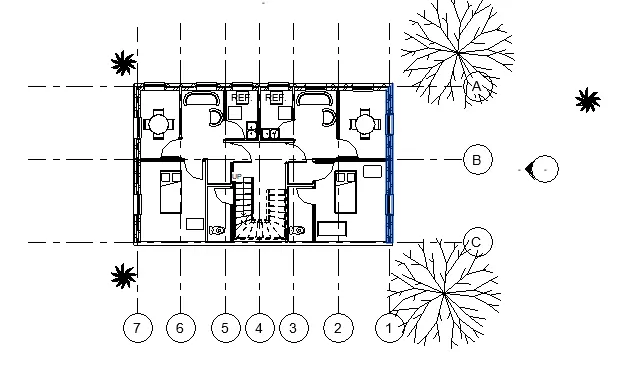
RESULT: Successfully added different components to the architecture.
5) Provide a set of drawings in an architectural and structural model to list the following details with categories and appropriate sheet templates included
a. Floor Plans with Annotations
b. Elevations
c. Sections
AIM:To provide a set of drawings in an architectural and structural model to list it in the appropriate sheet templates
INTRODUCTION:
Create views on a project template before you start building the model to streamline the project documentation proess.When creating a project template can include sheets in the template. Start with a blank project file and create the standard views and levels that each project should include. Leave the views empty, but assign standard names to them. To create the standard set of construction documents create sheets using desired title blocks
An elevation is a view of a building seen from one side. It is used to describe the external appearance of a building. Each elevation is labelled in relation to the compass direction it facesSectional views reveal hidden details in the drawing. These views assume that a cutting plane has removed portions of the object represented by the drawing, displaying the appropriate section of the interior. The sectional views are used in engineering drawings and architectural drawings.
PROCEDURE:
fo to the sheet option ,as the sheet opens there is another option below it called views
and select the required view you want to place.
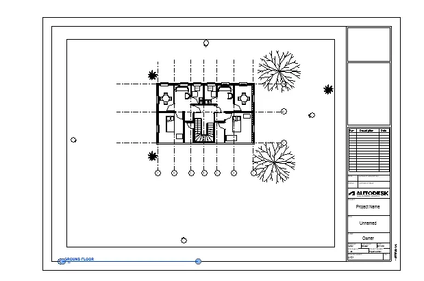
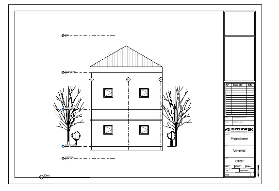
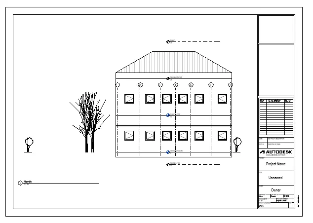
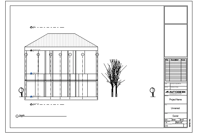
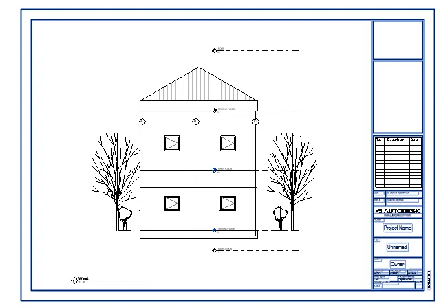
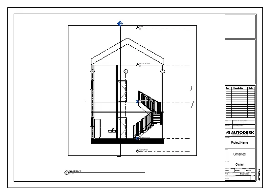
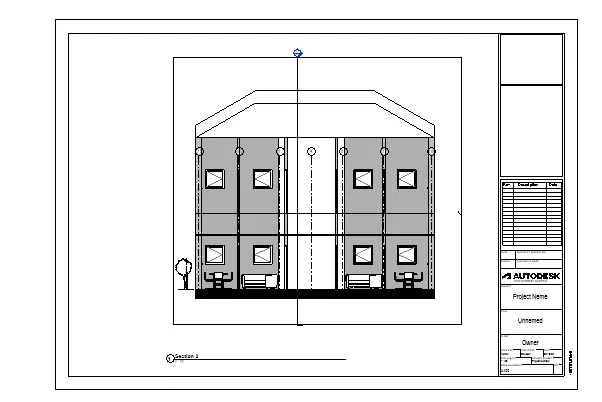
RESULT:provided a set of drawings in an architectural and structural model to list it in the appropriate sheet templates
6) Using the Rendering settings, Render images of the 3D model produced and include the rendered images to the drawing sheets
a. Rendering from interior rooms
b. Rendering from out showing topographic features
c. Rendering through structural framing
AIM:
Using the Rendering settings, Render images of the 3D model produced and include the rendered images to the drawing sheets
a. Rendering from interior rooms
b. Rendering from out showing topographic features
c. Rendering through structural framing.
PROCEDURE:
in order to render any figure go to the render option from the ribbon and change the settings you want
and click render figure will turn to realistic
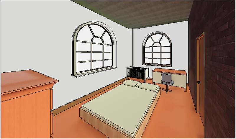
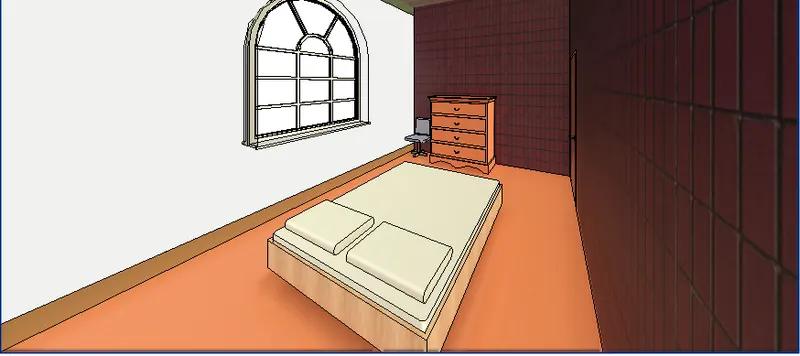
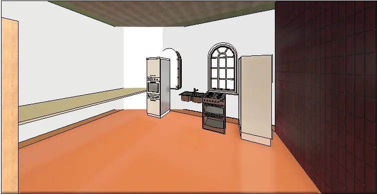
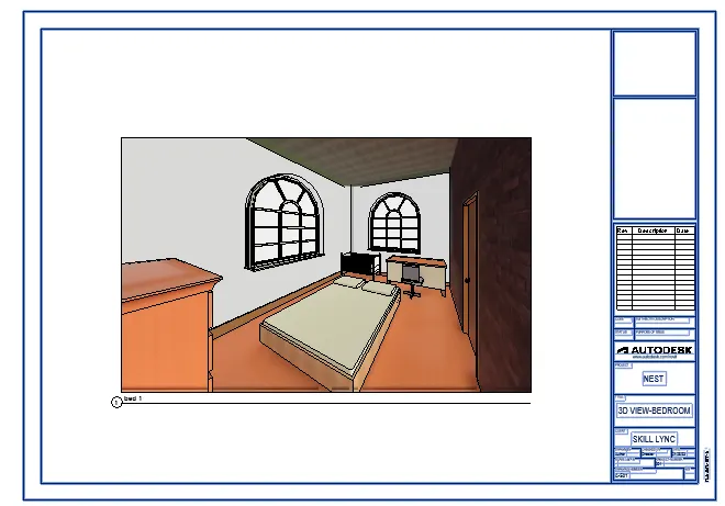
RESULT:Rendering is done successfully
7) Print the set of drawing sheets created and submit the drawings from the architecture and structure model
AIM: To print the drawing view
PROCEDURE:
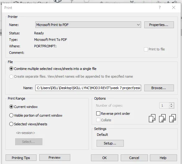
Click print
The option is available in the dialogue box
take the print
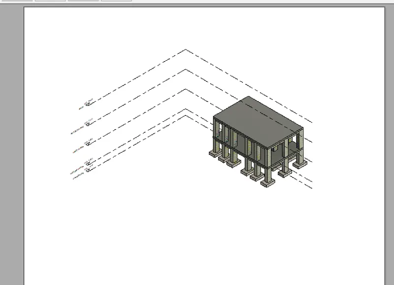
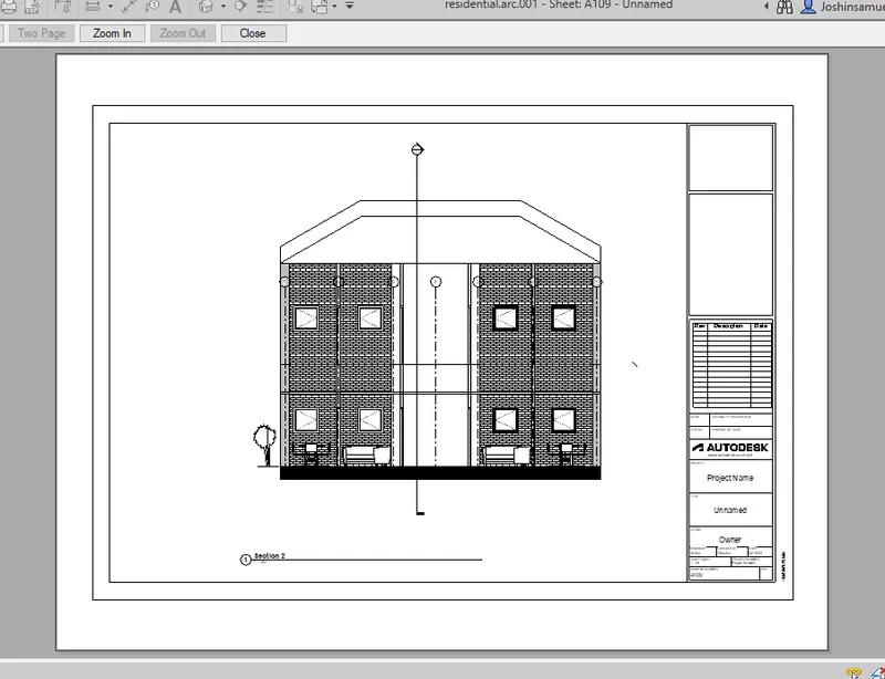
RESULT: Successfully taken the print