Creating Kitchen layout, Hatching of Architectural elements and sectional view of an Industrial Building in AutoCad
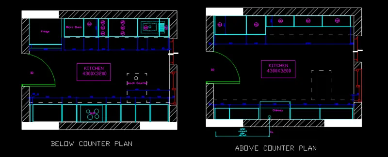
1)Create the layouts of the Kitchen and provide hatches pattern as shown. Also, use blocks wherever required. Provide appropriate dimensions in the plan. Assume the size of doors, appliances and others as per the standards.
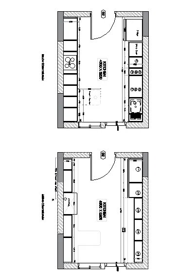
AIM: To create the kitchen layout and provide hatches pattern using blocks wherever required. All dimensions are in millimetres
PROCEDURE:
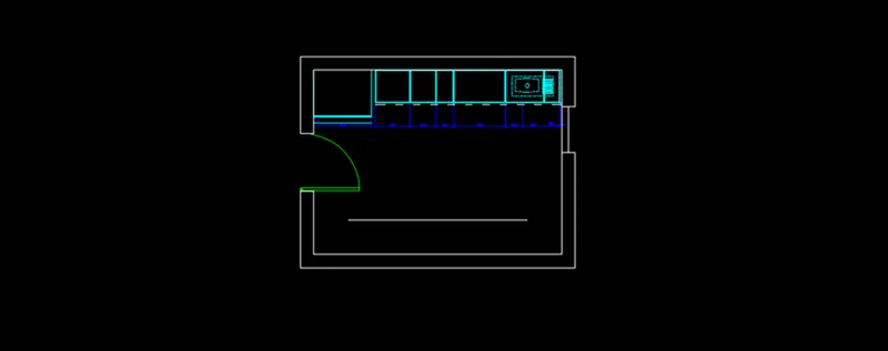
Below counter plan
- Create the new AutoCAD file
- Set the units to mm
- Create the layers required
- Set the limits
- Draw the line command by selecting the line command 4300 in X direction and 3200 in Y direction.
- Offset it to get the wall thickness of 230mm
- Trim the unwanted lines
- Draw the door and make it to block
- Insert the door in the plan
- Insert the window after created it as block
- Give the offset from the left side 90 as first offset 1000mm for fridge 300mm, 945mm and 35 mm
Above counter plan
- Copy the walls from the above plan
- Offset of 600mm from the top of the room to draw the kitchen platform
- Give the offset as mentioned in the reference plan
- Give the dimensions and text wherever required

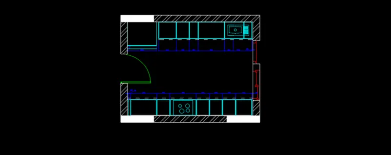
Hatching
- Command line enter H for hatch
- Pick the points wherever the hatch is required and enter
- Change the hatch type and colour or scale he hatch as per the requirement
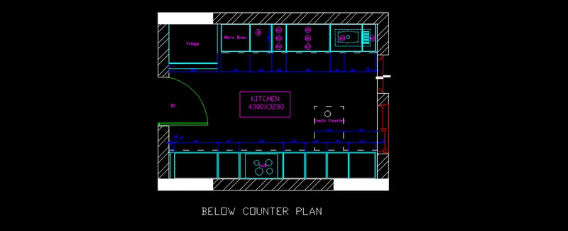
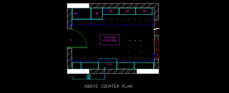
RESULT:Created the kitchen layout using the proper dimension techniques and provided the hatches wherever required
2) Create the elevation of the plan created in the Challenges 7 and apply proper hatch in the walls, doors, windows, and other architectural elements. Refer to the dimensions in Plans and sections in Challenges 7.
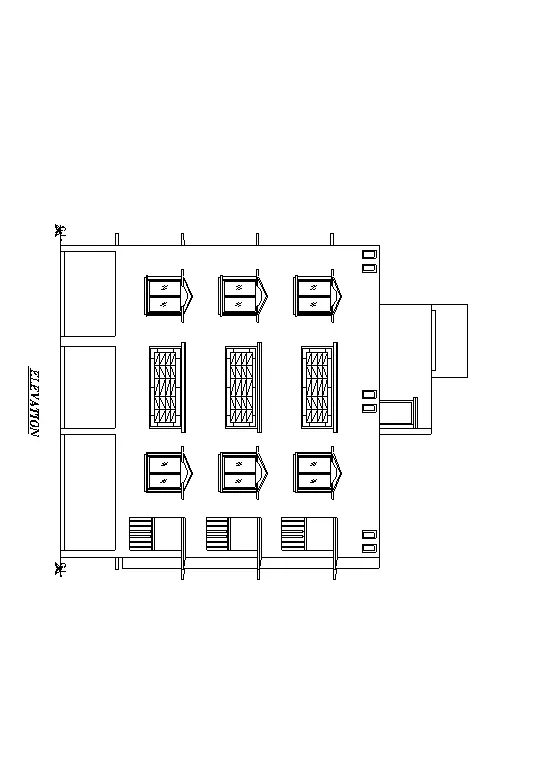
AIM: To create the elevation of the plan and apply the hatch properly
PROCEDURE:
- Select the Xline to project the outer wall from the plan
- Use the offset command to create the basement
- Create chajja using line command
- Offest the 2450 for the ground floor , 2850 for second and third floor
- Offset 1000 for parapet wall
- Offset 600 and 1200 for OTH
- Give the dimensions using dimlinear and dimcontinue
- Give the text by using Mtext
- Draw panel hatchg
- On the properties panel hatch type list
- Select the boundary objects Insert the object or pick the internal poiunts
- Change the hatch type and color as per the requirement
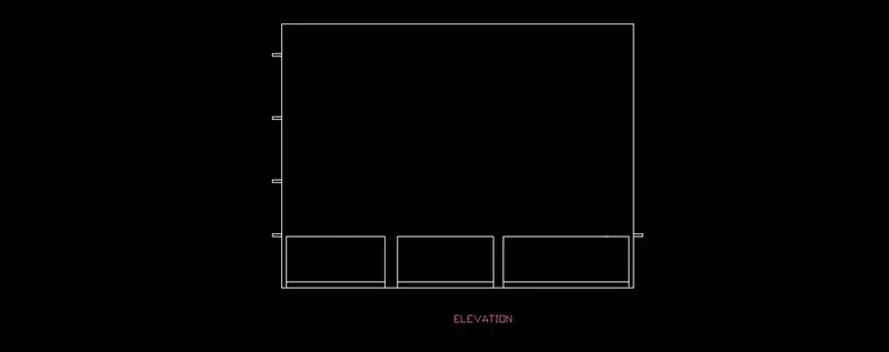
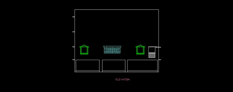
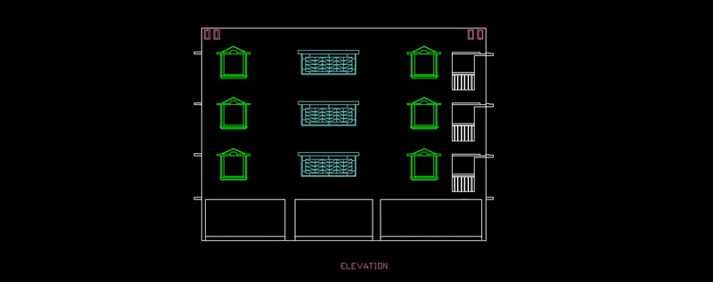
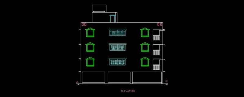
RESULT: Created the elevation of the mentioned plan
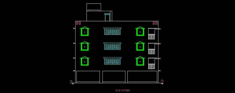
3. Create the section view of an industrial building as shown in Figure. Provide appropriate hatches and dimensions wherever required. Also, provide annotations to the drawing.
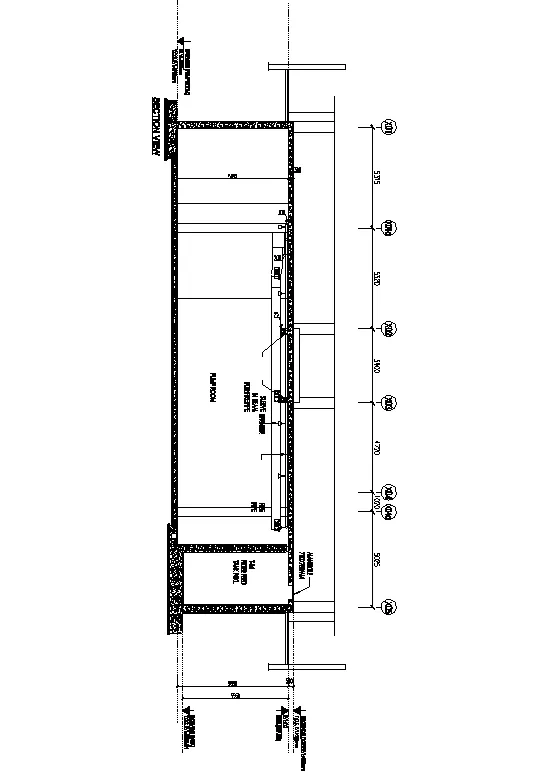
AIM: To create the section view of an industrial building, provide appropriate hatches, annotations and dimensions
PROCEDURE:
- Open the autocad file
- Set the units as decimal
- Create the layers that used to draw
- Draw the grid line using Xlines vertical
- Offset to the distance mentioned and complete the grid lines
- Command line and draw the horizontal line
- Offset the lines
- Hatch the portions with ARCONCRETE
- Draw the water tank, duct and fire pipe using lines, copy offset commands
- Select the dimension command and give the required dimension
- Select the multileader command and give the annotations
- Name the gridlines
- Give trhe text using dtext and mtext
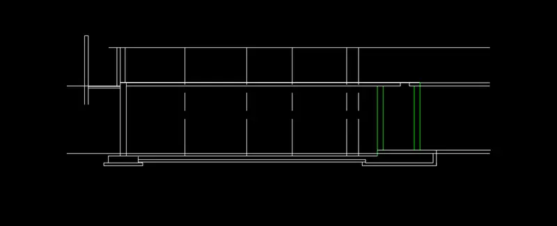
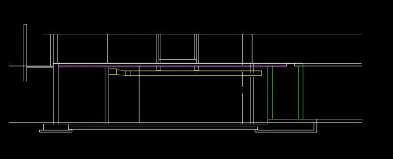
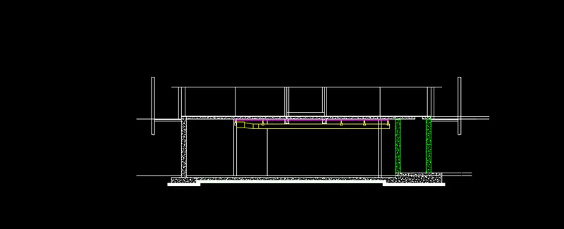
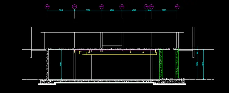
RESULT: Created the section of an industrial building
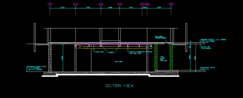
- Arun KumarWhat is the actual dimension for section?