Project 1 _Creating an Architectural plan for the provided plot size and develop relevant basic structural drawings
AIM:
- To draw the architectural drawing of a residential building for the provided plot size
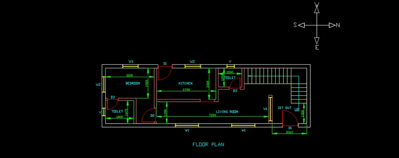
- Plan of a residential building
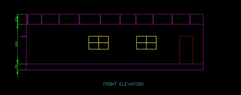
- Elevation of a residential building
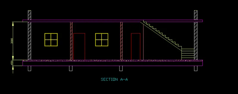
- Section of a residential building
- Structural drawing of a residential building
- Column plan layout of the building
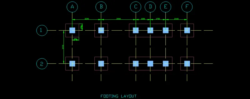
- Footing plan layout of the building
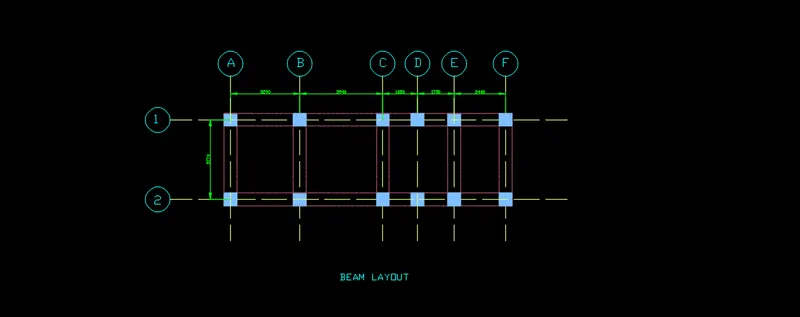
- Beam plan layout of the building
INTRODUCTION:
The buildings are planned based on the site availability and site condition, and it always obey building rules in that region. The efficiency of an architect is the utilisation of maximum space in the given area. The first stage of a designing of building is draft a floor plan. For the finished look of the building, we have to draft the elevation of the residential building. Section of a building is also important for the better understanding of each component.
The structural drawing is a set of plans that shows how a building structure will be built. It includes foundation details, framing details, columns and beam details.
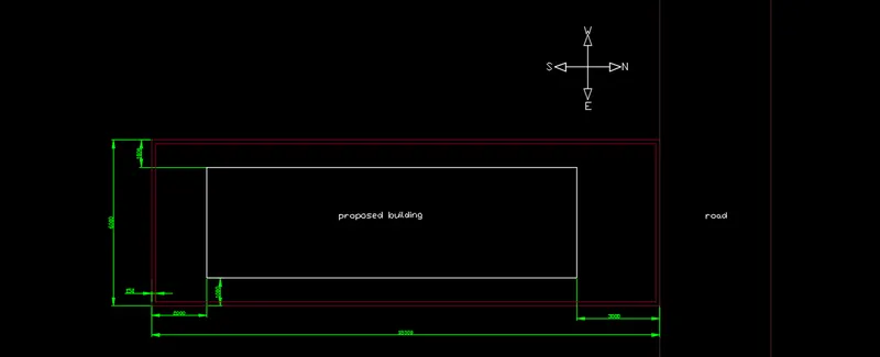
The proposed residential plan has east facing orientation and plot size is 18300mmx6000mm. The drawings provided are floor plan, elevation, section, column layout, beam layout and footing layout.
COMMANDS USED:
- Unit
- Limit
- Layer
- X-line
- Line
- Offset
- Fillet
- Hatch
- Block edit
- Dimension
- D-text & M-text
PROCEDURE:
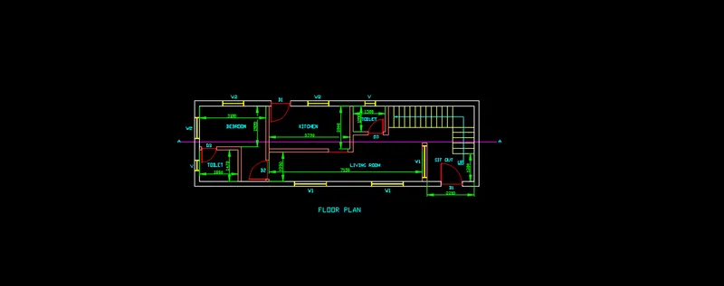
FLOOR PLAN
- Open AutoCAD new file
- Set the units as decimal-millimeters
- Set the required limits for the work
- Create different layers by command layer>new layers like external walls, internal walls, columns, beams, windows, doors, dimensions, text etc.
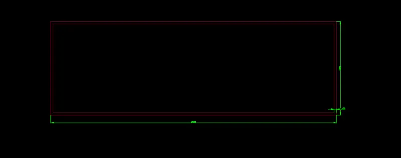
- Start the drawing by command rectangle and create the compound wall of plot size 18300 and 6000mm
- The building is east facing building
- Provide north direction
- Give setback as mentioned in the rule
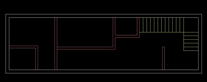
- From the given outline we have to develop a plan.
- Offset the outer wall thickness of 230mm and inner wall thickness as 150mm
- Trim the unwanted portions
- For staircase, tread is 250mm, riser 170mm , width 1000mm
- Create opening for doors
- Create the door and block editor
- Place the door in appropriate spaces
- Dimension the room sizes using dim command
- Create text
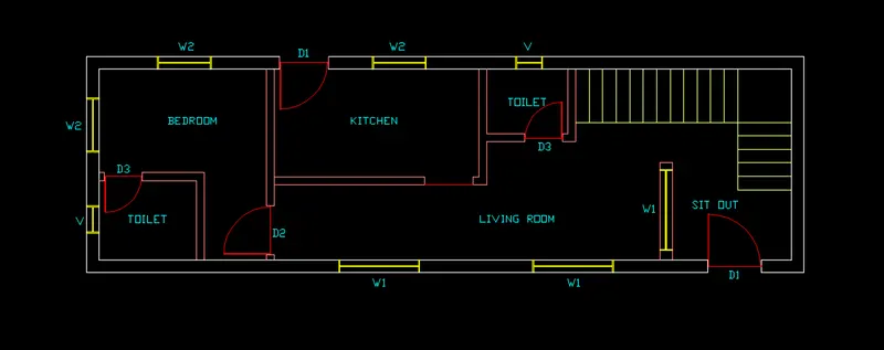
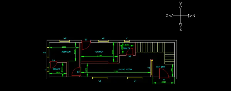
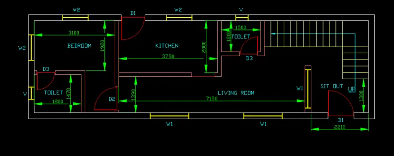
FRONT ELEVATION
- Project the lines from the floor plan using Xline
- Draw a horizontal line represent it as ground
- Take the offset of 450mm from ground level to get the plinth level
- Now offset the 3000mm from plinth line to get the height of the residential building
- Take offset of 750mm to get parapet wall
- Finish the projecvted door height of 2100mm
- Window size is 1500mm
- Trim the extended line
- Give the dimension
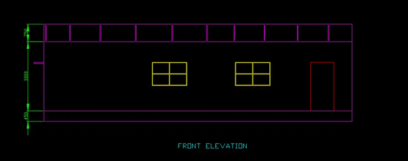
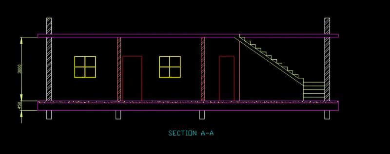
SECTION
- Project the lines from plan and elevation to get the dimensions of each components in the section
- Trim the unwanted lines
- Draw the staircase by cutting the section line , riser 175mm offset and to the second flight take riser and tread 230mm upto slab
- Finish the doors and windows from the projected lines
- Hatch the wall that are subjected to section
- Dimension the appropriates
COLUMN LAYOUT
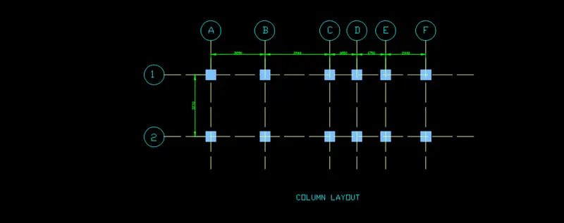
- Draw the centre line through out the wall and place the columns of dimensions 610mmx610mm in the corner of walls and intersections
- Delete the walls also and mark the gridlines in X and Y directions
- Provide dimensions
BEAM LAYOUT
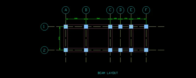
- Provide the beams by connecting the walls in the column layout
FOOTING LAYOUT
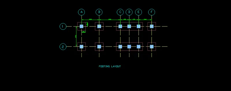
- Isolated and combined footings are provided
- Draw the rectangle of dimension 1500 and 1500mm and place in the reference to the column layout
- Mark the dimension
RESULT:
Architectural and structural drawings are completed for the proposed residential building