Creating Architectural and Structural model with 3D rendering using REVIT
PROJECT-2:
Creating Architectural and Structural models with 3D rendering using REVIT
AIM:
To Creating Architectural and Structural models with 3D rendering using REVIT
INTRODUCTION:
Revit software is developed by the Auto desk in the year 2002. It is most useful for Architectures, Civil engineers, and MEP engineers by Drafting and Design. The Revit platform for building information modeling is a design and documentation system that supports the design, drawings, and schedules required for a building project.
Building information modeling (BIM) delivers information about project design, scope, quantities, and phases when you need it. In the Revit model, every drawing sheet, 2D and 3D view, and schedule is a presentation of information from the same underlying building model database. As you work in drawing and scheduling views, Revit collects information about the building project and coordinates this information across all other representations of the project.
The Revit parametric change engine automatically coordinates changes made anywhere—in model views, drawing sheets, schedules, sections, and plans. To Creating Architectural and Structural models with 3D rendering using REVIT using Architectural, Manage, and View tabs simultaneously The Course structure of Revit is,
- Concept sketch
- 3D model
- Design Standards
- Evaluation of Performance
- Optimization
- Drafting and Drawing.
QUESTION NO 1:
Select the type of structure you want to build from one of the three below:
a. Multi-Unit Residential Apartment
b. Office Buildings
c. School
ANS:
The structure I want to build from this project is a "Multi-Unit Residential Apartment".
QUESTION NO 2:
Assume reasonable assumptions for geographic and location details for your project modeling. Based on assumptions and the type of structure selected identify the modeling requirements from NBC.
ANS:
- The minimum depth of the foundation is kept 1m below the Ground level.
- Plinth Height of 450 mm is more commonly used for Residential houses.
- Plinth Area should be a minimum of 1.2 times the floor area of the residential building.
- The carpet area should be 50% to 65% of the floor area.
- The main entrance door of a residential building should be 1000 mm x 2100 mm in size. Other doors should have a minimum width of 900 mm and height of 2000 mm. Doors for the garage are 2500 mm x 2300 mm and for W.C. and bathrooms are 600 mm to 750 mm x 1800 mm with single-leaf shutter
- The size of windows depends on the total area of window openings required. The following guidelines should be kept in mind:
(i) Window width =1/8 (width of room + height of room).
(ii) Glass area in windows should be 10% to 20% of the room's floor area for good lighting.
(iii) At least one sq.m. of window area should be provided for every 30 cubic meters of inside room space. Generally, the window's minimum size is 750 mm x 1000 mm.
(iv) Window sill level (bottom of the window) is 900 to 1200 mm above floor level.
-
The minimum ventilator size is 1000 mm x 500 mm to provide good ventilation for any habitable room. For bath and w.C., it should be a minimum of 450 mm x 300 mm. Its depth should be not greater than 450 mm or otherwise privacy is lost.
-
Sizes of various rooms of a residential building:
i)Drawing room or Living Room:4200 mm x 4800 mm to 5800 mm x7200 mm
ii)Bedroom: 3000 mm x 3600 mm to 4200 mm x 4800 mm
iii)Dining Room:3600 mm x 4200 mm to 4200 mm x 4800 mm
iv)Kitchen:2500 mm x 3900 mm to 3000 mm x 3000 mm
v)Bath and WC combined:1800 mm x 1800 mm to 1800 mm x 2500 mm
vi)Bath separated:1200 mm x 1800 mm
vii)W.C. Separated:1200 mm x 1200 mm
viii)Guest room: 3000 mm x 3600 mm
ix)Storeroom: 2500 mm x 2500 mm to 3000 mm x 3000 mm
9. Stairs:
- Rise in residential building 130 mm to 190 mm
- Tread = 275 mm to 350 mm for public buildings Tread =250 mm to 300 mn for residential buildings.
For selecting the rise and tread of a building, the following thumb rules are followed:
- T+2xR = 550 to 650
- TxR=39000 to 48000
- The width of steps is 1000 mm for residential buildings and is range from 1500 mm to 2000 mm for public buildings.
- Number of risers total height of floor height of the riser
- A number of treads =Number of risers-1.
10. The thickness of R.C.C. lintel beam is 100 mm to 250 mm and 150 mm is more common.
11. Thickness of the R.C.C. roof slab is 100 mm to 150 mm (100 mm is more common) and that of sunshades is 25 mm to 50 mm
12. Sunshades project through 450 mm or 500 mm beyond the facing of external walls.
13. Width of the verandah is from 1.8 m to 3 m and the width of the passage is 0.8 m to 1.2 m in residential houses.
14. The height of the parapet wall should not be less than 0.60 m and not more than 1.2 m above the finished floor level.
QUESTION NO 3:
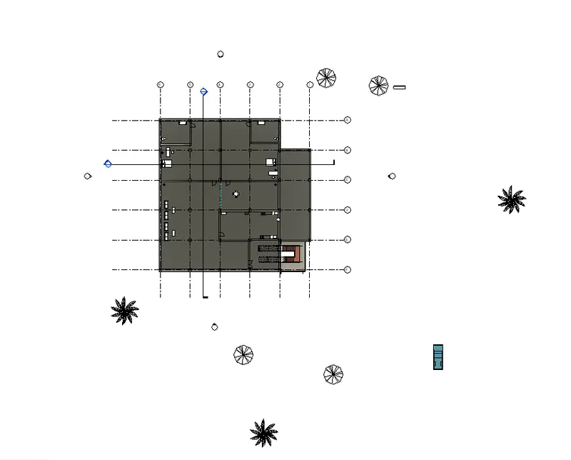
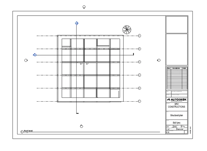
Using the structural model, include the following components based on the type of structure selected
a. Foundation – Isolated / Wall/Matt Foundation
b. Columns
c. Beams Connected to Columns
d. Roof Framing/ Truss
e. Floor / Decks
f. Floor Openings for Elevators and Stairs
PROCEDURE:
1. Open the Revit 2023 software.
2. After that create a Structural template.
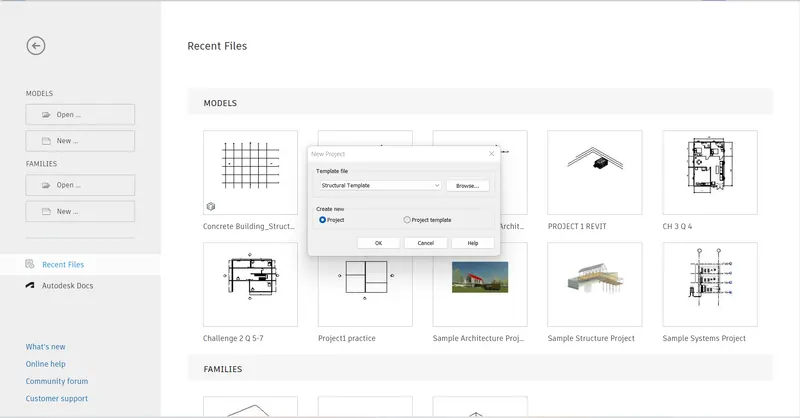
3. To save the Structural template as a "Project2_Structural_Residential".
4. Now set the project information and project units.
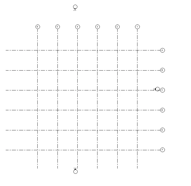
5. Now in the Structural template, create Grids and levels.
6. Go to Structure>Select option Grids>To Draw Grids longitudinally and Transversely.
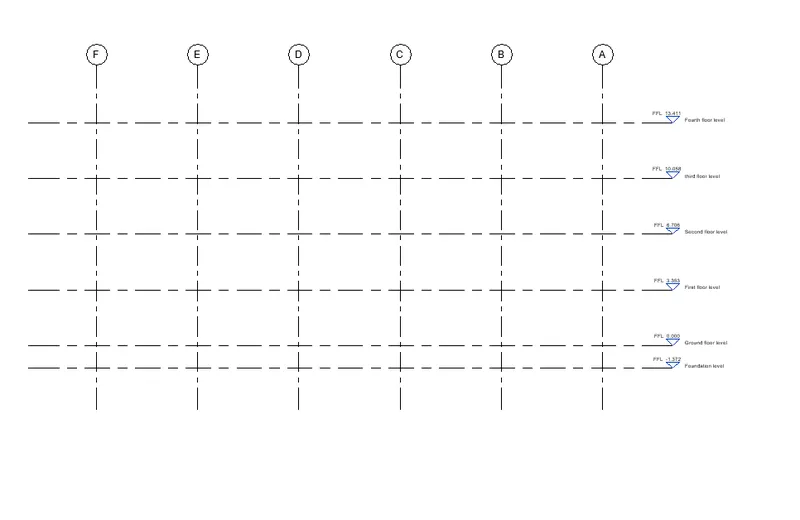
7. Now Create the Levels in the structural template. Go to Elevation views and select levels to offset the height 12' and rename it all Structural levels.
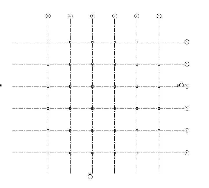
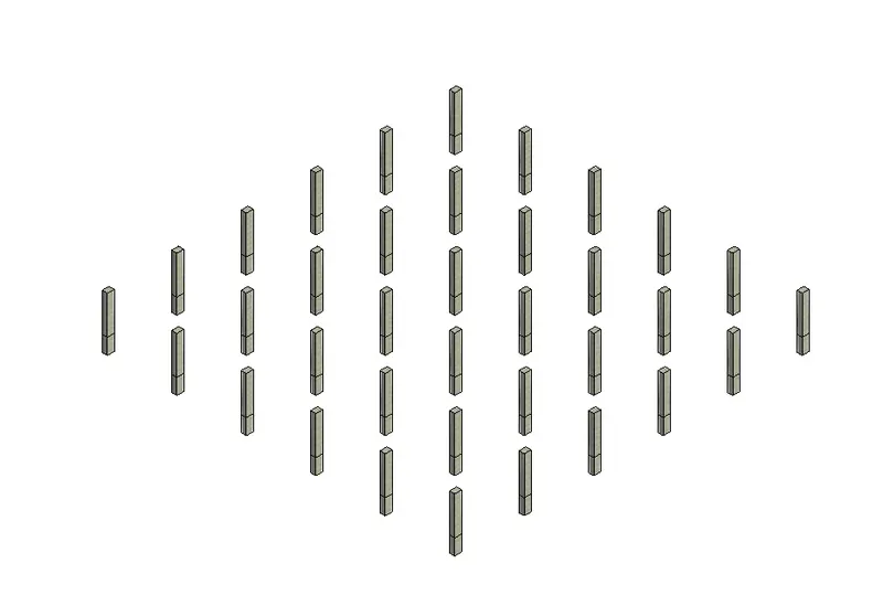
8. After that To Create Columns, then go to Structure Tab>Select columns to select grids and draw them.
Size of an RCC column= 450 x 600 mm.
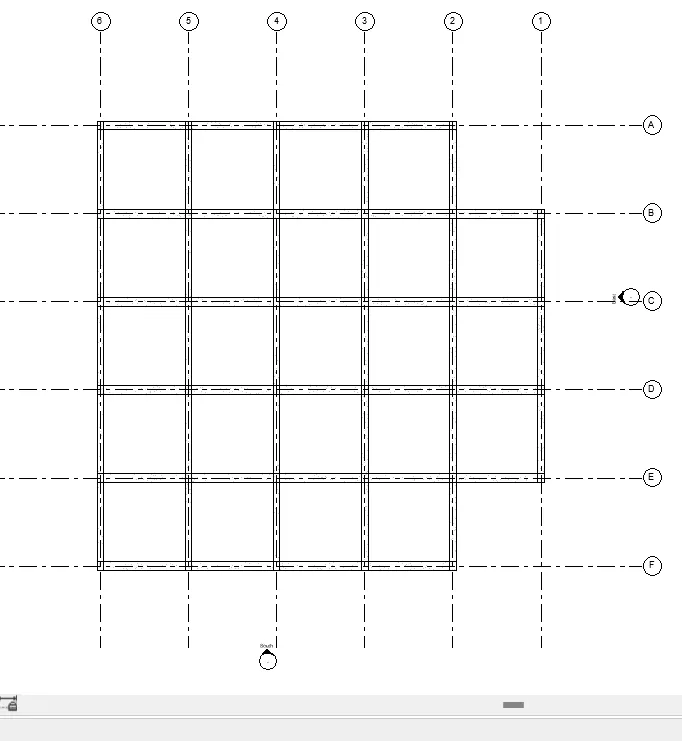
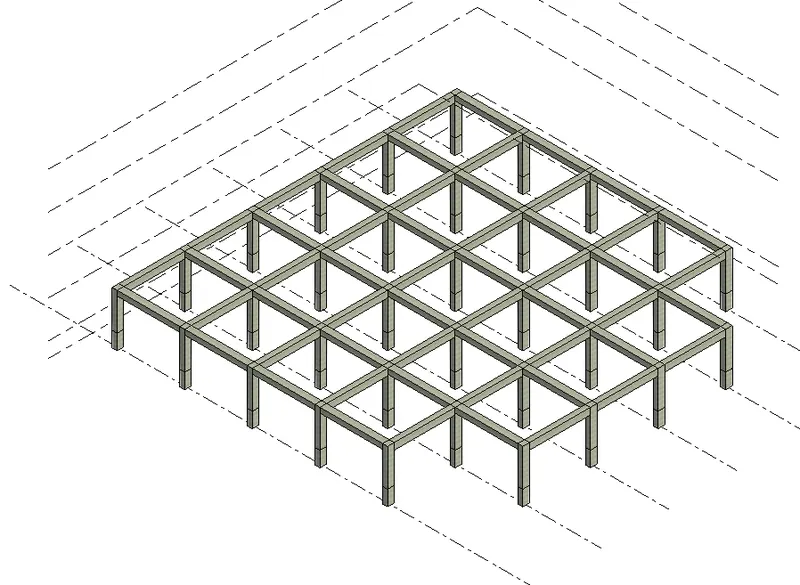
9. After that To Create Beam connected columns then go to Structure Tab>Select beams to select grids and draw them.
Size of an RCC Beams=600x450 mm and 450 x 650mm.
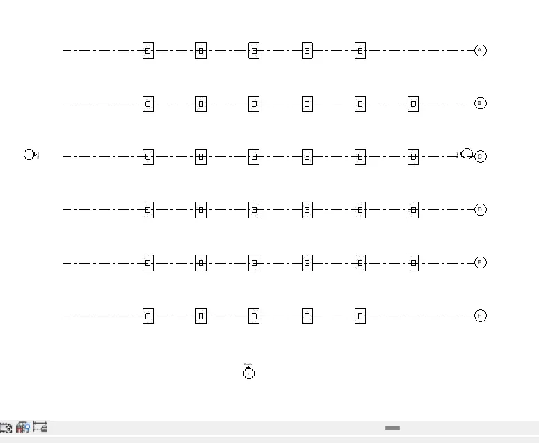
10. After that To Create a Foundation, then go to Structure Tab>Select Isolated Foundation to select grids and draw it.
Size of an Isolated Footing= 1800x1200x450mm.
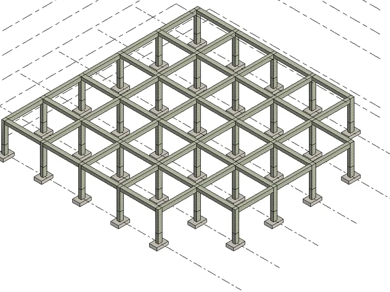
11. After that copy the structural framing elements adjusted to the select levels.
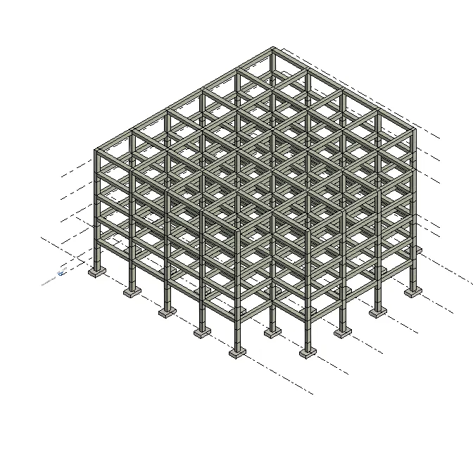
12. After that To Create Floor then go to Structure Tab>Select structural floor option to select lines and draw them.
The size of an RCC floor= Generic 300mm was selected. First draw the ground floor level and copy it to all levels.
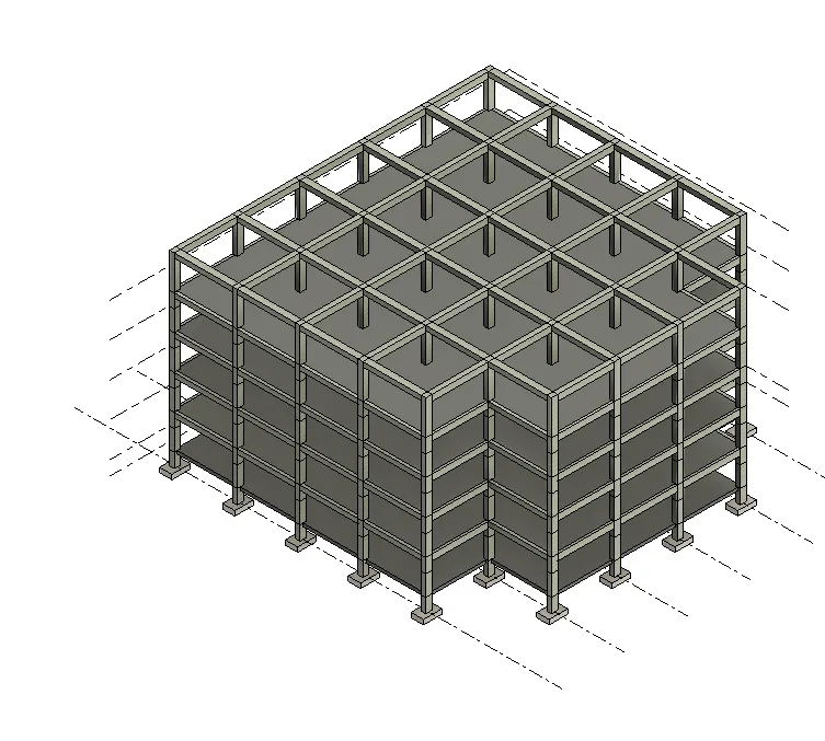
QUESTION 4:
Using the architectural model, include the following components based on the type of structure selected
a. Wall Layout with appropriate material and finishing
b. Exterior façade with fancy finish
c. Interior partition walls to size rooms
d. Components to add details to a room ( Desk, Chair, Lighting, Plumbing fixtures)
e. Add components such as stairs Elevators
f. Have at least one side of the building with curtain walls and glass panels
g. Include interior and exterior lighting fixtures
h. Place proper topographic components from outside ( Trees, Parking, Plants) to add details to the model
PROCEDURE:
13. Now open the Architectural model.
14. To add the structural model into the architectural model by using the manage links. Once linked to the Structural model then select the Revit link copy monitor tab and select all grids and copied it. similarly, the levels also copy into the structural model into the architectural mode.
15. After that create floor plans for all floors.
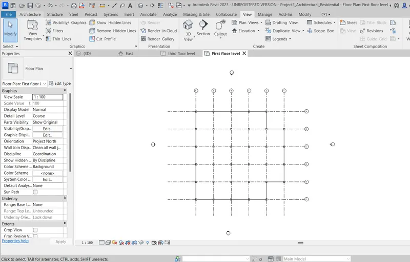
16. Now Create an Architectural wall for floor plans. Go to the Architectural floor tab>select wall and draw it.
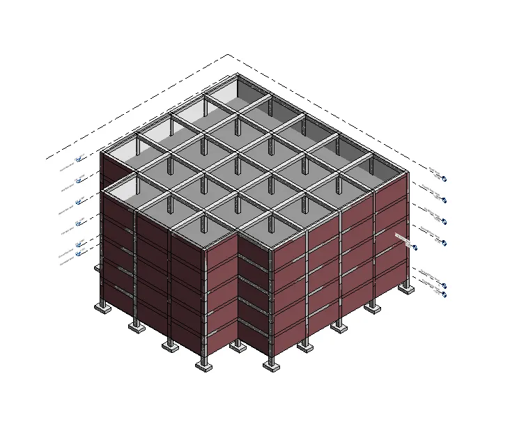
17. I have to create in the front wall curtain wall storefront in replace generic 300mm wall.
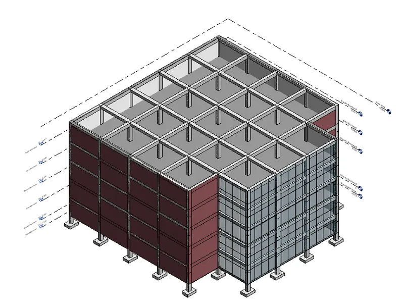
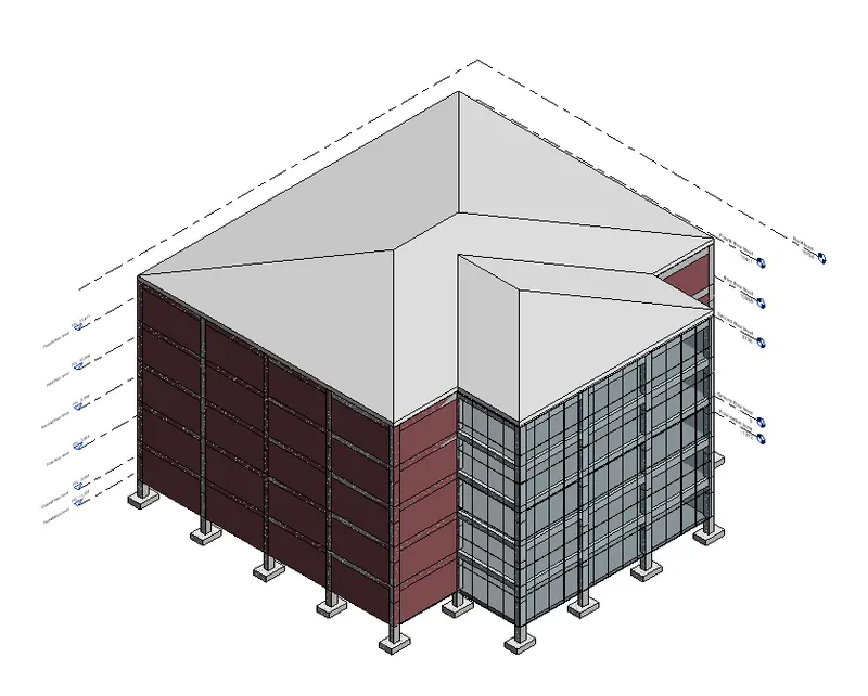
18. Now create the roof of the entire multi-storied building and then Go to the Architecture tab>Select Roof option >To select lines draw to the roof level.
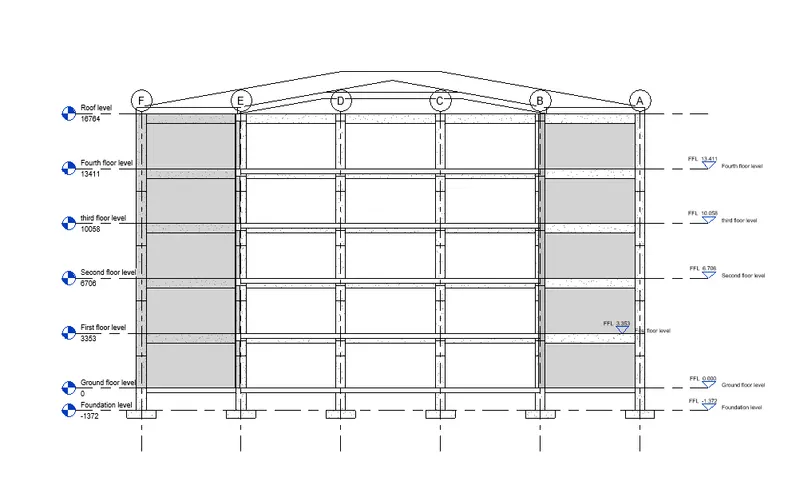
19. Now create the Staircases for all floors by using the Architectural tab>Go to stair and draw the all floors.To show the Stairs in elevation views.
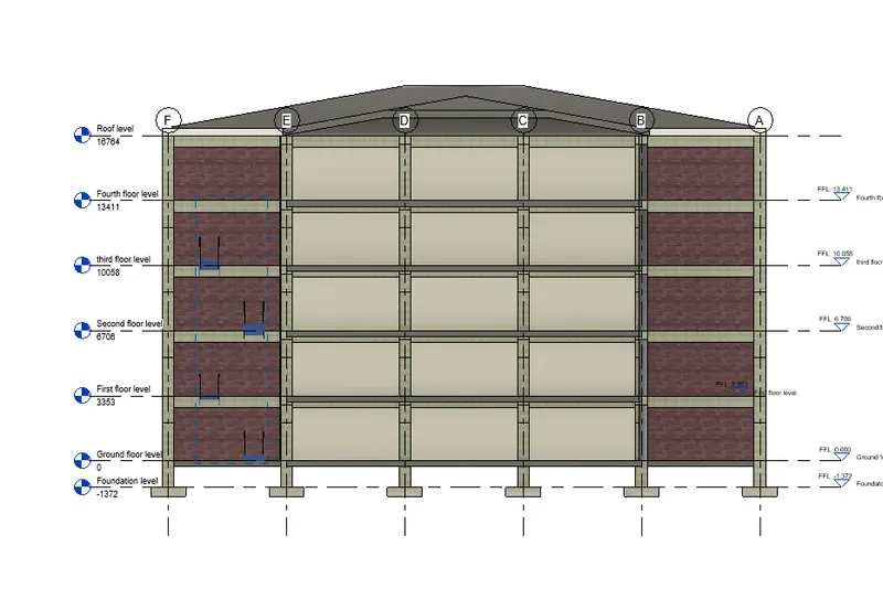
20. Now create the Floor Generic 6" for the landing to the staircases and that floor copy to all levels.
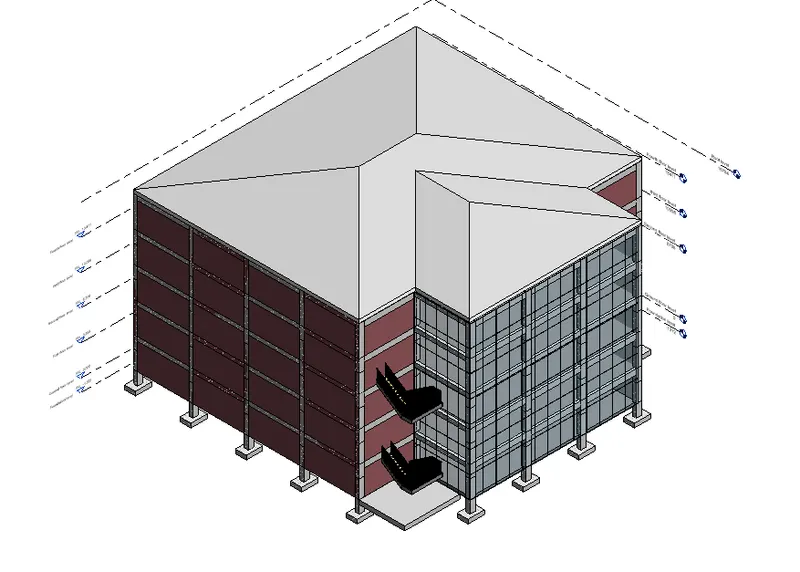
21. Now provide for shaft opening for staircases .Go to Architecture tab>Selected for Shaft and to select lines and tocreated.
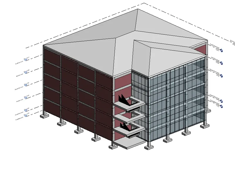
22. Now create curtain walls to the staircases and finally inserted them into the roof level slab.
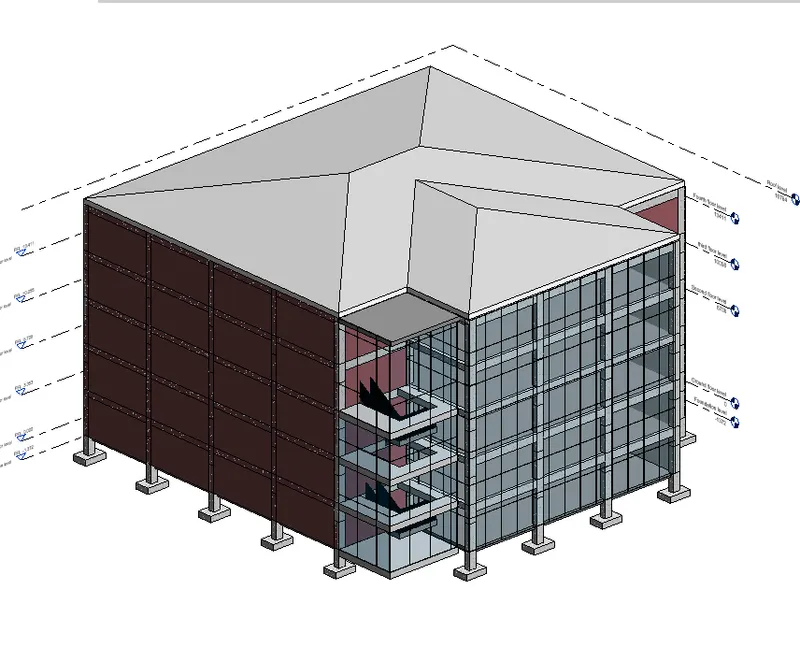
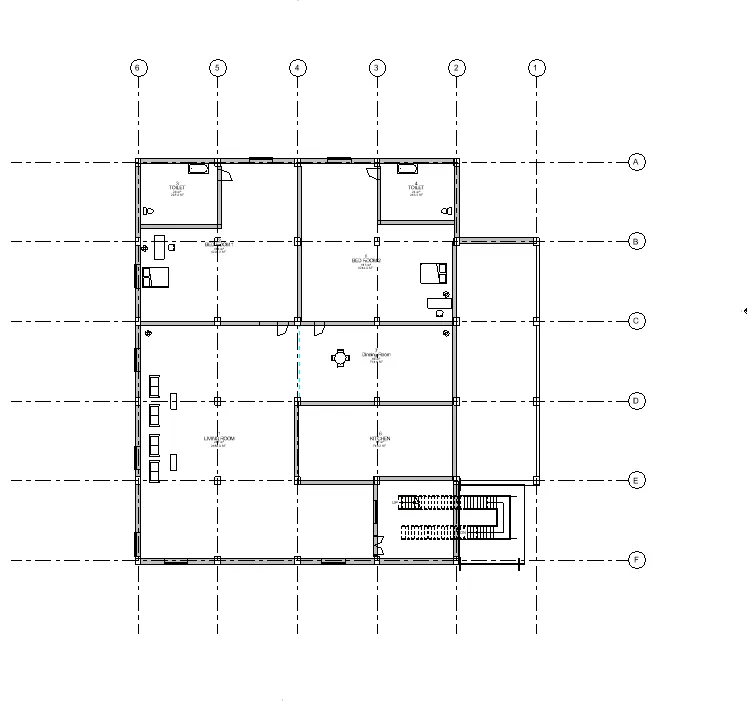
23. Now created all interior walls(Generic 4.5" wall) in the building of the first floor to select all four floors in the multistoried building. Also, tag these rooms with proper Annotations.
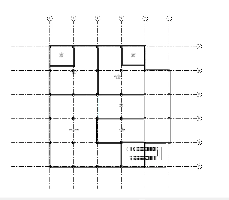
24. Now Created All elements in the building and copied them to all floors.
QUESTION-5
Provide a set of drawings in an architectural and structural model to list the following details with categories and appropriate sheet templates included
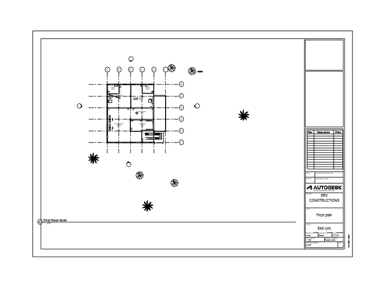
a. Floor Plans with Annotations
b. Elevations
c. Sections
PROCEDURE:
a.Floor Plans with Annotations:
b. Elevations:
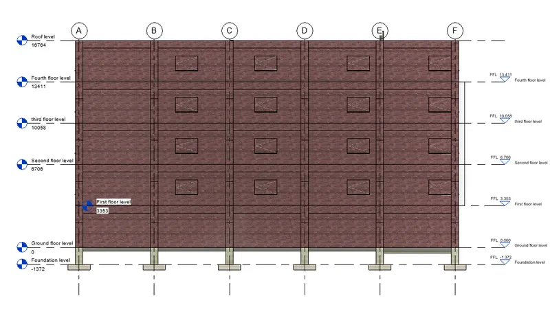
EAST:
WEST:
NORTH:
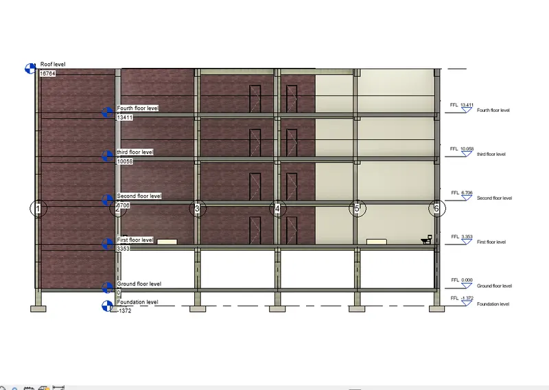
SOUTH:
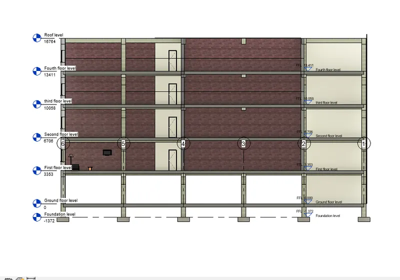
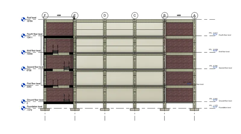
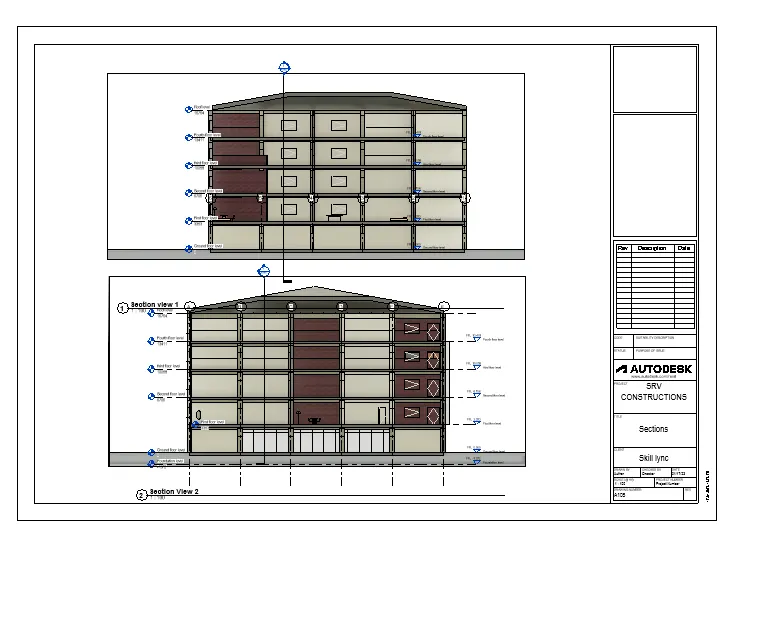
c. Sections:
View1:
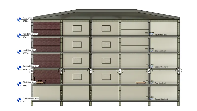
View2:
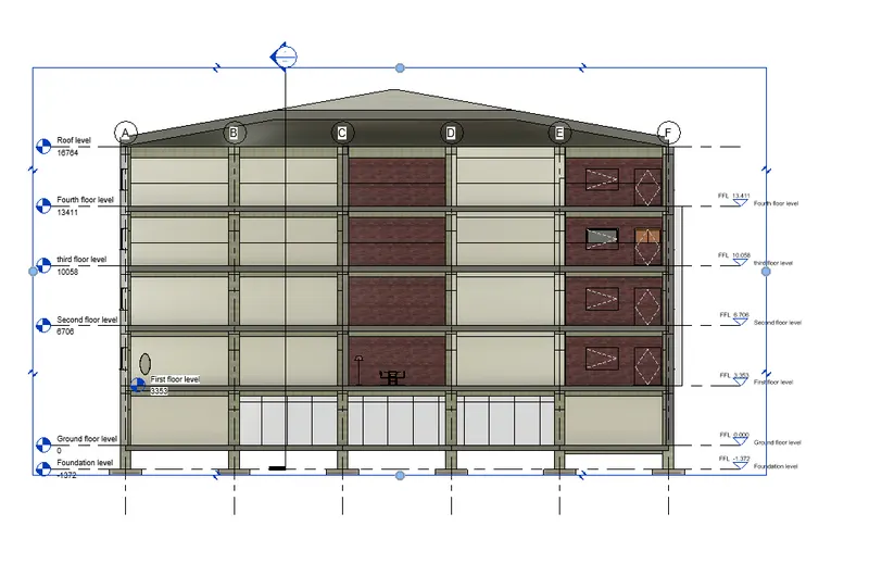
QUESTION 6:
Using the Rendering settings, Render images of the 3D model produced and include the rendered images to the drawing sheets
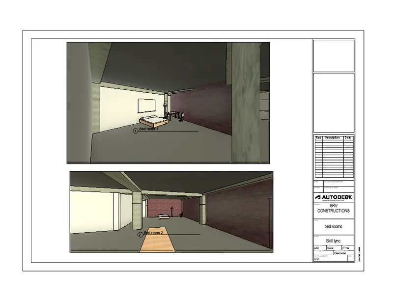
a. Rendering from interior rooms
b. Rendering from out showing topographic features
c. Rendering through structural framing
PROCEDURE:
a. Rendering from interior rooms:
Bed Room 1:
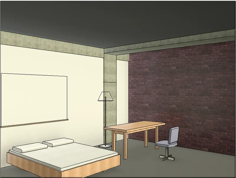
Bed Room 2:
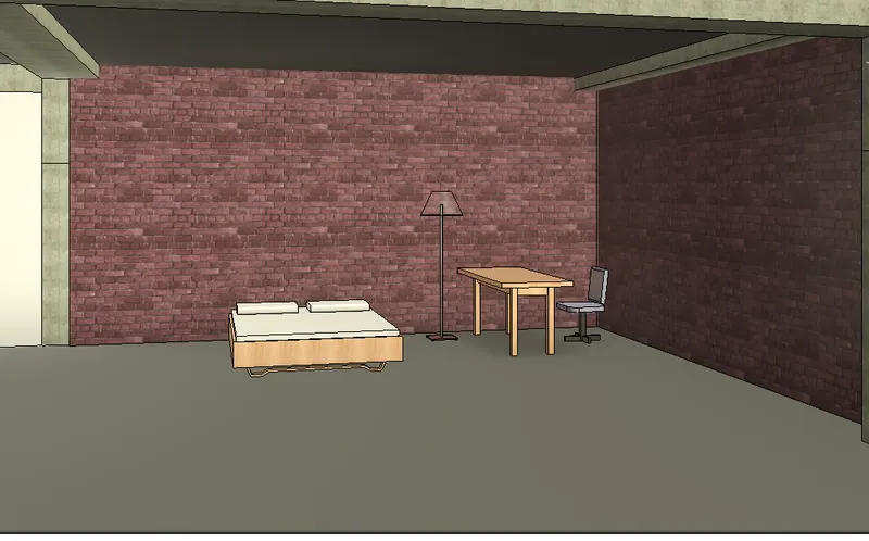
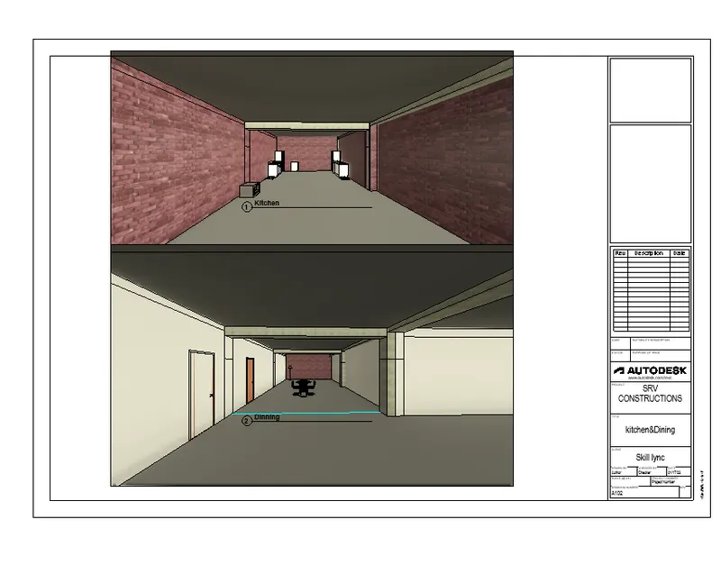
kitchen:
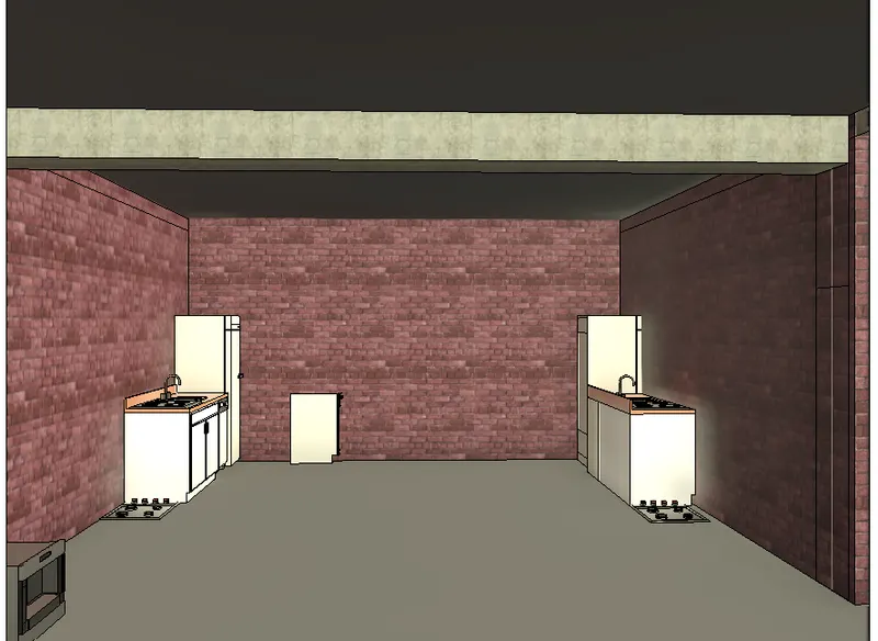
Dining:
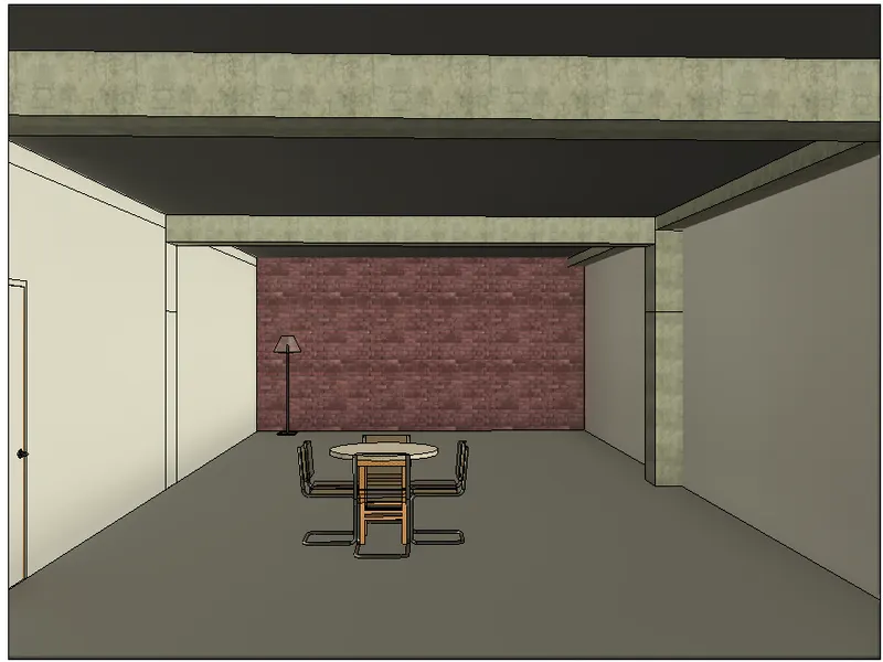
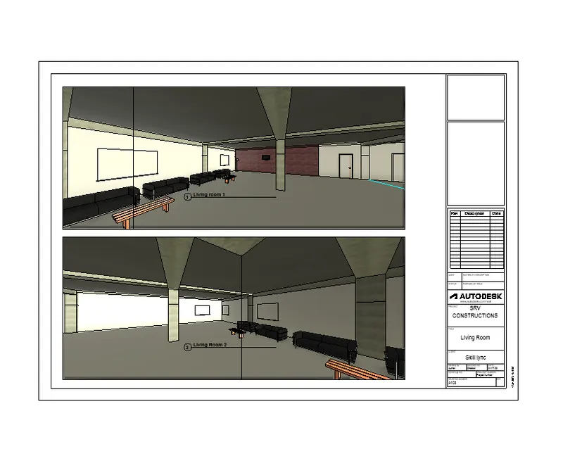
Living Room:
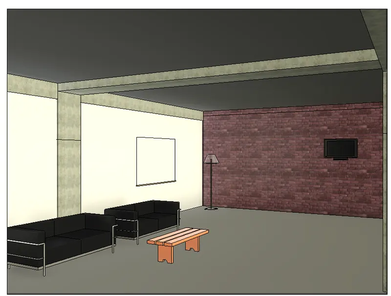
Living Room 2:
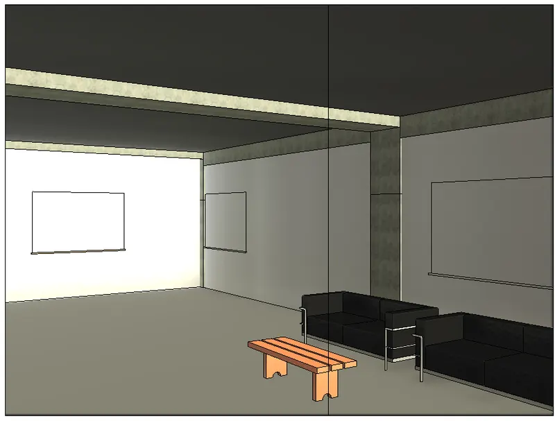
Toilet:
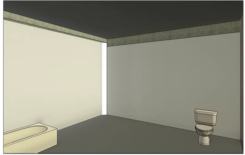
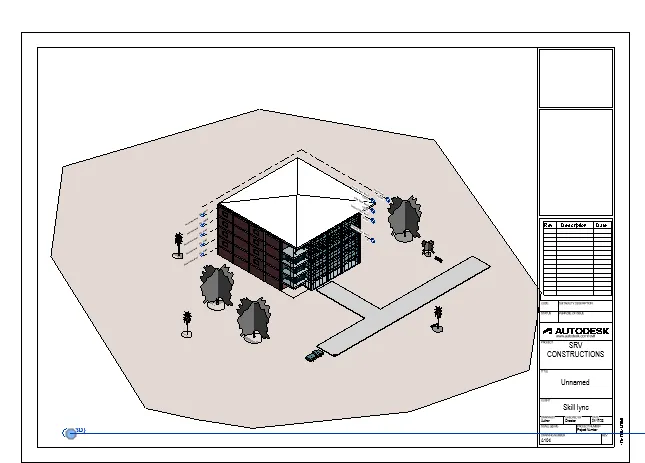
b. Rendering from out showing topographic features:
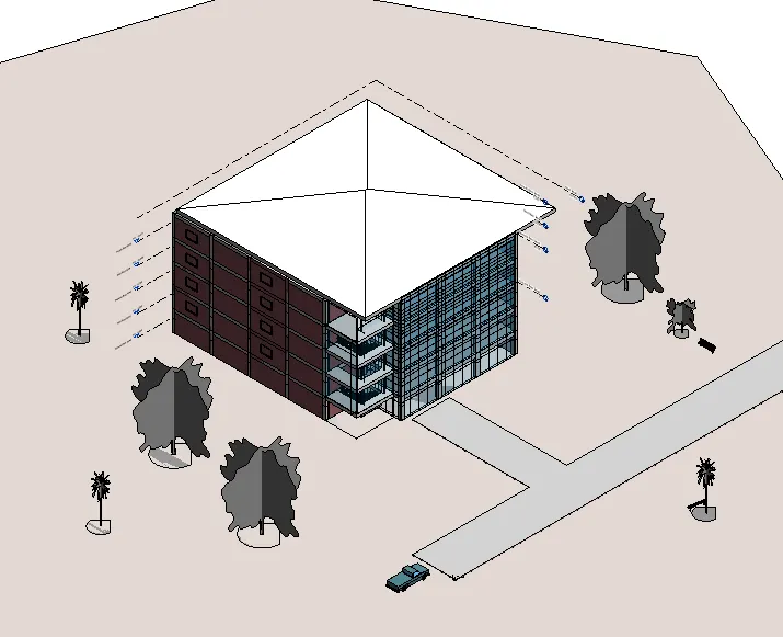
c. Rendering through structural framing:
QUESTION NO 7:
Print the set of drawing sheets created and submit the drawings from the architecture and structure model
PROCEDURE:
Floor plan:
Structural plan:
Bed Rooms:
Kitchen and Dining:
Living Rooms:
Sections:
Topographic Outline View 3D View:
............................................................ END ...............................................................................................