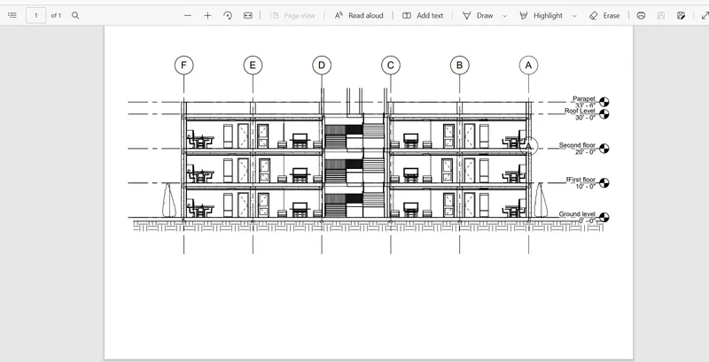
Creating Architectural and Structural model with 3D rendering using REVIT
Aim: Creating Architectural and Structural Model with 3D rendering using Revit
Introduction: Revit provide us all type of furnitures and type of walls doors and etc., we can add and modify all type of elements. We can creata a structure model of the builing separate and Architechtural separate and we can link them by rebit link option.
Q1. Select the type of structure you want to build from one of the three below:
a. Multi-Unit Residential Apartment
b. Office Buildings
c. School
Ans. I have choosen Multi-Unit Residential Apartment
Q2. Assume reasonable assumptions for geographic and location details for your project modeling. Based on assumptions and type of structure selected identify the modeling requirements from NBC
Ans.
1. As mentioned my building comes under residential category and it can be situated in the center of the city.
2. My project is located near the ring road.
3. The road width in front of my building is 60'.
4. The heigh area and safety measureswill follow the rulesand regulations of NBC.
5. The height of my project is 42' and the road width is 60'.
6. So my building height is 12.8 m and the road width is 18.2 m, the height of the building should not exceed 1.5 times the width of the road width.
7. In this case the building height is not exceeding so it is suitable for construction.
Q3. Using the structural model, include the following components based on the type of structure selected
a. Foundation – Isolated / Wall/Matt Foundation
b. Columns
c. Beams Connected to Columns
d. Roof Framing/ Truss
e. Floor / Decks
f. Floor Openings for Elevators and Stairs
Ans. We have created a Grids in challenge 6. Same in that way e have create a Architectural and Structural model with grids and and collaborated and linked them in one combineed model
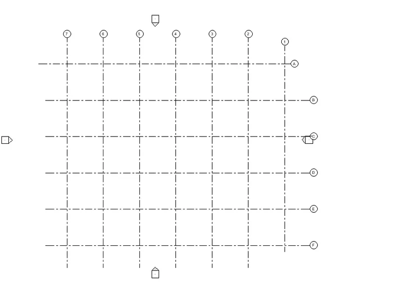
- After creating the grids link them and make them at to occur same project base point
- Now we linked them
- Now open the Structuraol model that we created with grids
- Creat the levels of foundation,ground floor,first floor,second floor,roof level and parapet
- Now select the level called foundation from the project browser
- Go to structural tab and select the option called isolated foundation
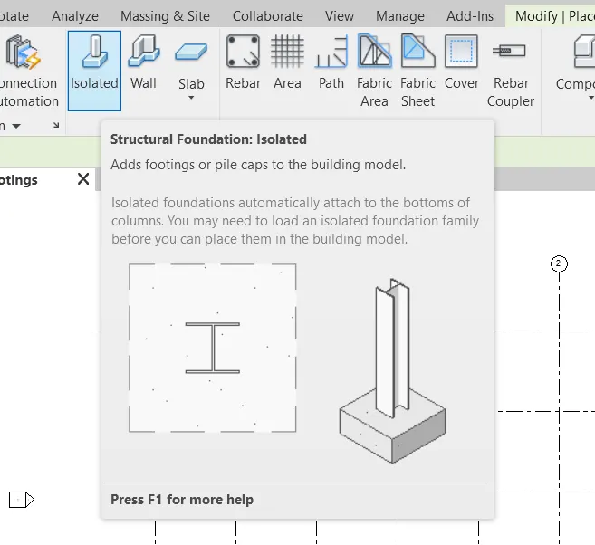
- After selecting the foundation select the option called at grids so we can place the foundation at grids
- Now select all the grids and place a foundations
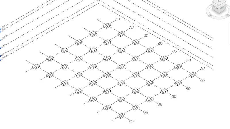
- Now go to structural tab and select the option called columns
- And select the option called at grids and place a columns at grids
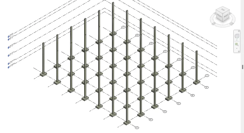
- Now select the option called beam and place beams at grids
- If beams are not available go to load family and load the type of beams
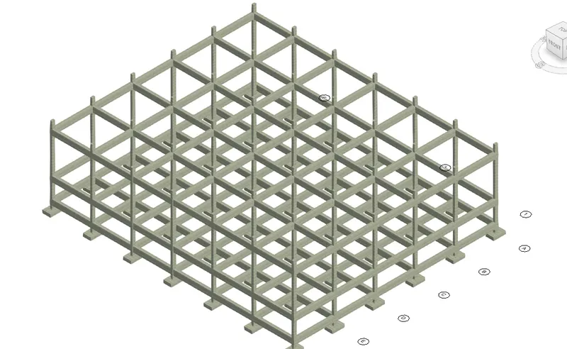
- Now create structural floors of each levels
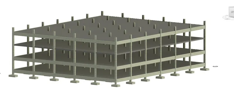
- After creating the floors create a shaft for strairs
- Go to strctural tab and select the option called shaft
- Choose rectangle from the draw panel
- And create a shaft from first floor to roof
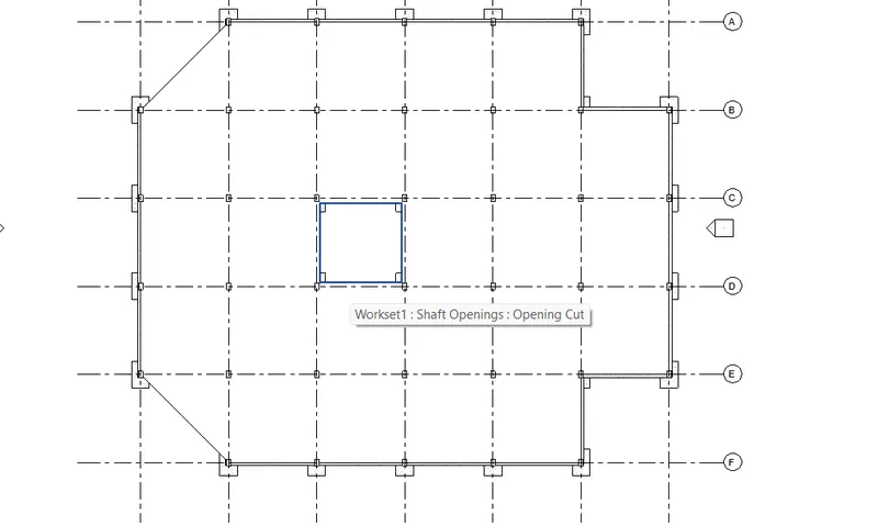
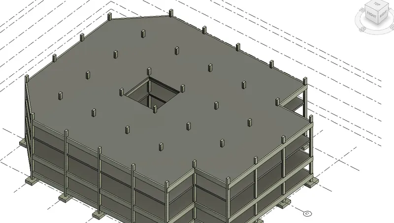
- We get below result after creating the footings,columns,beams,roof and shafts
- Close the structural model and synchronize with central
Q4. Using the architectural model, include the following components based on the type of structure selected
a. Wall Layout with appropriate material and finishing
b. Exterior façade with fancy finish
c. Interior partition walls to size rooms
d. Components to add details to a room ( Desk, Chair, Lighting, Plumbing fixtures)
e. Add components such as stairs Elevators
f. Have at-least one side of the building with curtain walls and glass panels
g. Include interior and exterior lighting fixtures
h. Place proper topographic components from outside ( Trees, Parking, Plants) to add details to the model
Ans. Now open the architectural tab
- As we can see that the structures that we created in the structural model is shown in the architectural model
- Now in architectural model we create a walls,doors,windows,furnitures and etc.,
- Use wall tool create a walls with a appropriate thickess
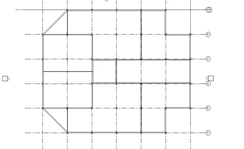
- After creating the walls now add furnitures
- By using componet tool add furnitures
- Go to load family and load all type of furnitures that we need
- Add doors by using door tool
- Add windows by using window tool
- Add desk,chairs,watercloset,dinning tables,sofas and etc., that we need
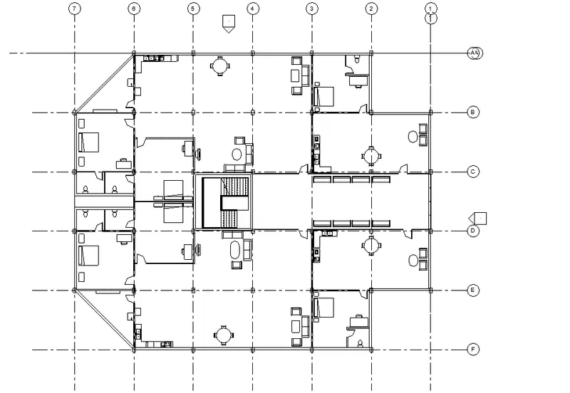
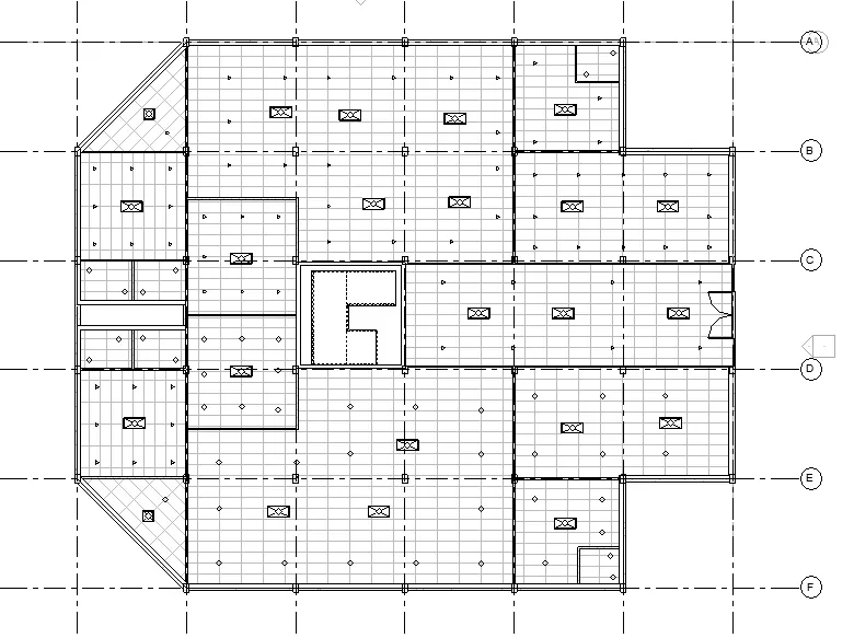
- Also create a ceilings in each room and place a interior lighting fixtures
- Ceiling are created each and every floor
- And also create a topography and create a parking area by using different type of elements
- Create a curtain walls by using the curtain wall tool
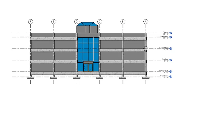
- Add topographic to the model and add trees to the model
- Add parking area
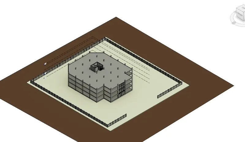
Q5. Provide a set of drawings in an architectural and structural model to list the following details with categories and appropriate sheet templates included
a. Floor Plans with Annotations
b. Elevations
c. Sections
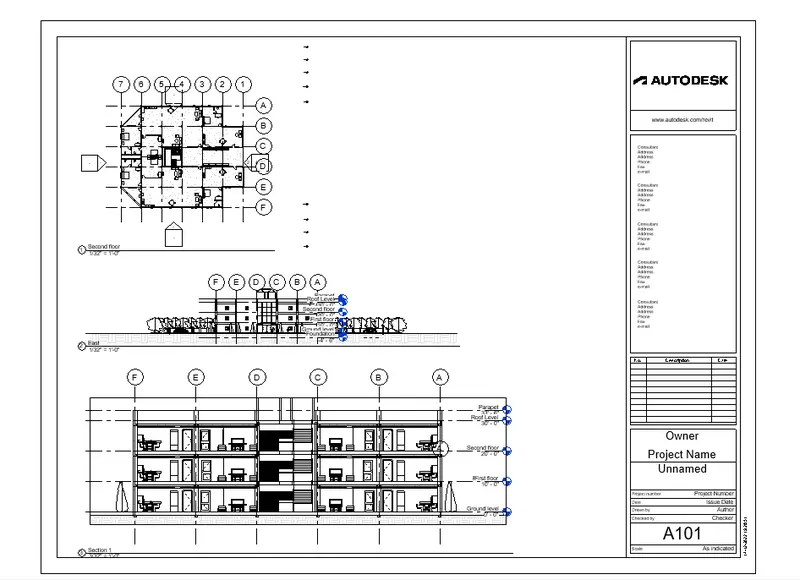
Ans. Create a new sheet by using sheet option in the tab
- Rename the sheet with appropriate name
- Drag the views from the project browser
- Set a suitable scale to fit the drawing in the sheet
- We a below sheet after draging the drawings in the sheet
Q6.Using the Rendering settings, Render images of the 3D model produced and include the rendered images to the drawing sheets
a. Rendering from interior rooms
b. Rendering from out showing topographic features
c. Rendering through structural framing
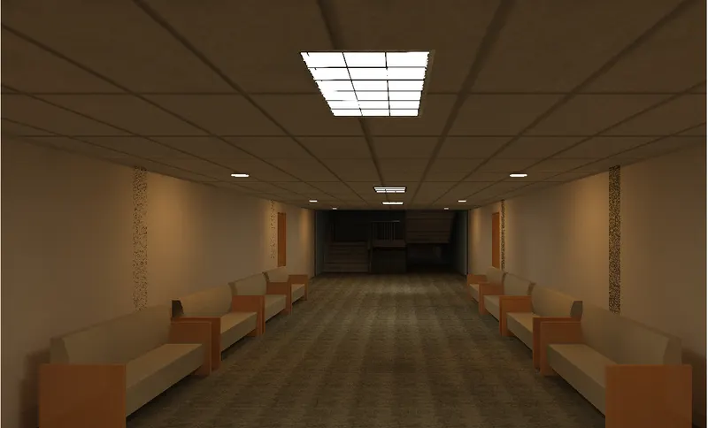
Ans. Go to view tab as we can see that camera option place a camera in rooms to create diferent views of the room
- After placing the cameras in the room Choose a option called render from the view tab
- Set the custom option and select the type of scheme to create
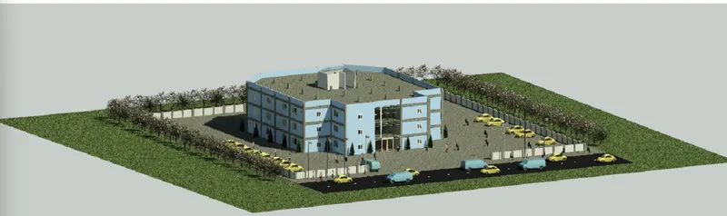
- And also create a outside rendering view of the building to show the topographical features
- And also create a rendering image if structural farming from the structural model
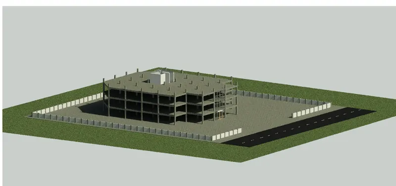
Outside rendering image to view the topographical views:-
Structural farming rendering views:-
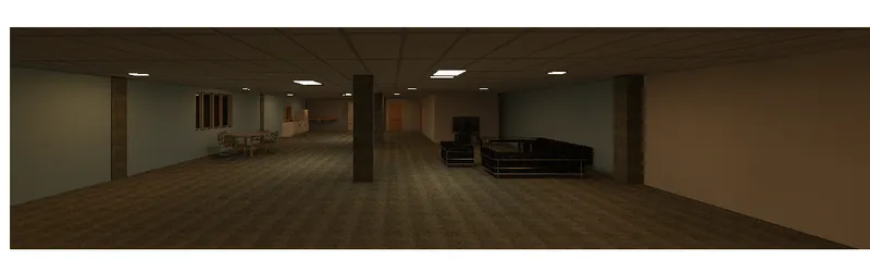
Placing the cameras and rendered the views of the rooms
1. Kitchen and living room rendering view
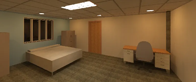
2. Ber room rendering view
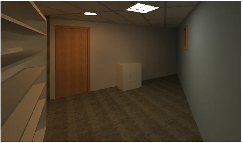
3. Store room rendering view
4. Verandah rendering view
Q7. Print the set of drawing sheets created and submit the drawings from the architecture and structure model
Ans.
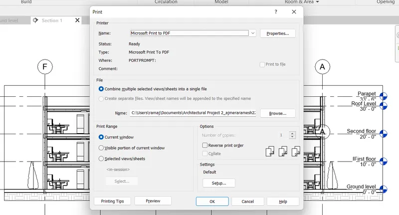
To print or save model in the pdf formate of the drawing on the paper just click CTRL+P on the keyboard
Select the view that we want to print or save
- We will see a dialog box select the page size and no. of copies if the drawing
- Ans oress ok
- Then select the pdf file location
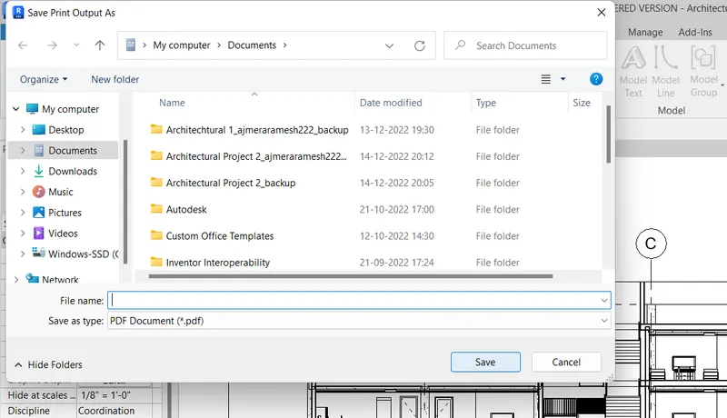
- And click on the save
- Now the pdf file of the drawing is saved
Result