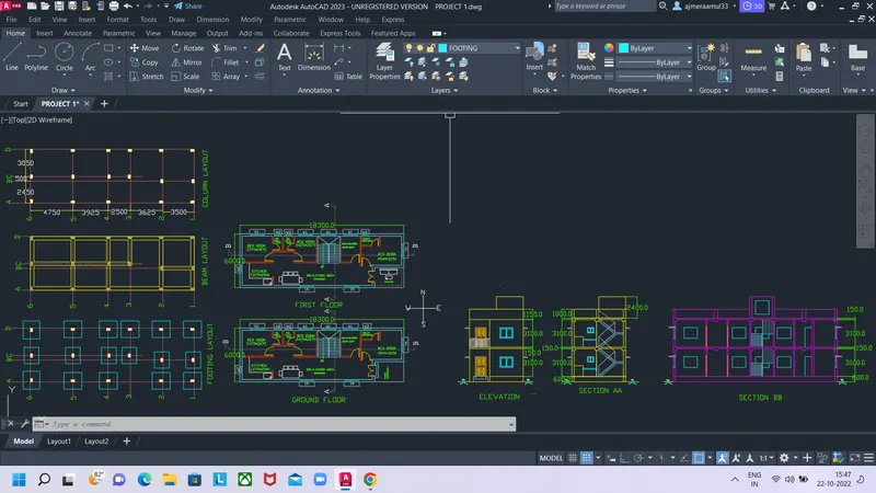
Project 1 _Creating an Architectural plan for the provided plot size and develop relevant basic structural drawings
Aim:
Creating a layout of a residential building by using autocad with the following details:
a. Plot Size: 60’x20’(18.3m x6m)
b. Orientation- Facing East
c. Develop the following: 1. Architectural Drawing (Floor Plan, Elevations, and Sections) 2. Structural Drawing (Column, Bean, Footing Plan)
Introduction:
Creating a architectural drawing of a residential building of G+1 by using autocad facing east. Every point of a drawing is shown in diagram. The sections and elevation are shown clearly in autocad. And also creating a structural drawing (columns,Beam,Footing Plan).
Step by step procedure for plan:-
Type UN in the command line and set the units in decimal and set the presicion
After setting the units type limits in the command line
Set the lower limit as 0,0 and upper limit as 25000,25000
Then type Z enter and E enter to fit the screen
Create different types of layers line exterior wall,interior wall,doors,windows, dimensions,text,sunshades
Select the suitable colours to those layers
Now starting the drawing with a command REC by selecting the exterior wall layer
Type the REC in the command line
Specify the starting point
Then select the DIMENSION give the length as a 18300 and breadth as a 6000
Specify the end point
Give a internal offset of 250 by using command OFFSET
250 Will be the thickness of the exterior wall
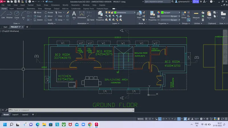
Draw a foyer of dimesion 3250*2250 by using offset tool FOR GROUND FLOOR
The foyer is provided in front of main door
Now the BED ROOM is drawn with a dimension of 4500*3250 with a attached bathroom 2000*1000
The corners of rooms are setted by the tool FILLET with radius 0 and tool TRIM.
The interior wall thickness is provided of 125
Then the drawing room is drawn with a specifiction as 2125*2875
Space for staircase is provided of 2500
Tread - 200
Riser - 163.158
After the staircases another bed room is drawn with a 2425*2875
And given the bath room specification as a 1125*1650
Another bed room is drawn with a dimensions of 3375*2875
Bath room dimensions are same 1000*1650
The kitchen is drawn a with a specification of 3375*2500
Remaining space is provided for the dinning area and living area
Now the doors are drawn
D = 1200*2200
D1=900*2200
D2= 750*2200
Now the windows are drawn
W1=1500*1200
W2=700*600
The steps are provided on front of main door
Sunshades are drawn by using line tool with a dash line type
Now the Ground Floor drawing is completed
By using DTEXT command write a text for indication of the room
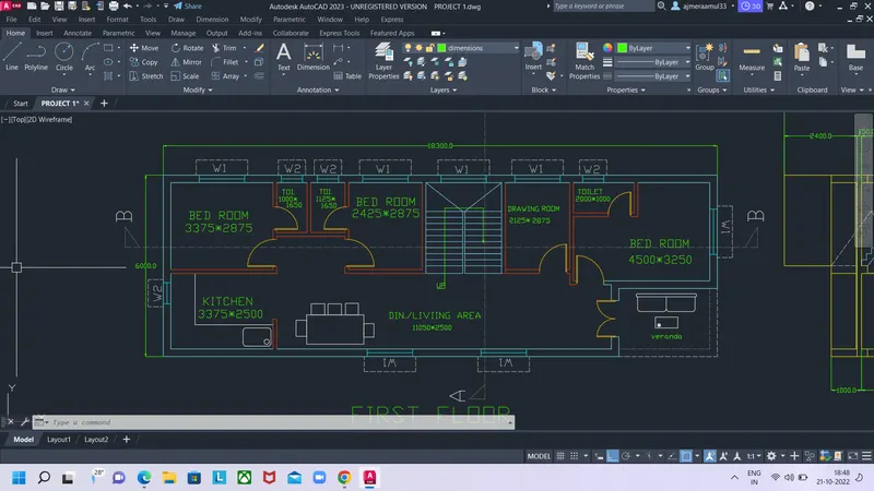
Now for first floor drawing copy the ground floor
In first floor the foyer area is turned as veranda
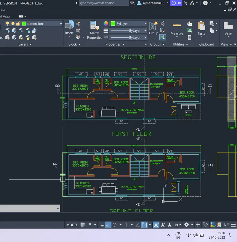
Relust:-
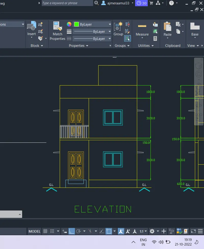
Procedure for drawing Elevation:-
For elevation take a front view of building
By using the XLINE tool project the front view of a plan what we can see in the front view in the plan
First draw a plinth with a thickness of 600 by using the offset tool
Give a height of 3100 of ground floor by offset tool
And give a sajja of thickness 150 which is connected
And give a first floor height of 3100
The height of parapet wall is given as 1000
And the awning like structure is provided to the staircase area on the top of the building
The door is drawn two side open door
The windows are also drawn
Result:-
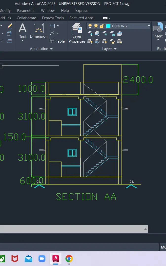
Section AA
By using the XLINE tool the lines are projected from the cutting section
In section we see the beam,slab, c/s of the staircase
The staircase is provided with a
Tread - 200
Riser - 163.158
The depth of the beam is taken as 350
The width of the beams taken as 400
The kitchen is view is visible
The window is shown in the kitchen
Height of ground floor 3100 from the plinth level
Height of first floor is also 3100
The parapet wall height is 1000
These all drawn by using the tool line
The fillet tool is used to set the corners of the rooms
The unwanted lines rae deleted by the tool trim
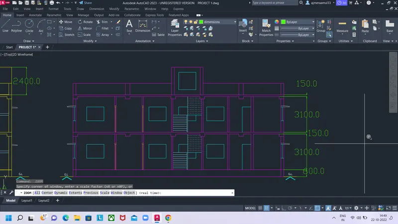
Section BB:
By using the XLINE tool the lines are projected from the cutting section
Same as the section AA the section BB is also drawn
By using fillet tool,line tool,rectangle tool,trim tool the total section is drawn
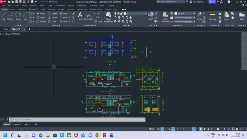
Result :
Plan of residential building G+1,sections over AA,BB and elevation of a building
Structural drawing (Columns,Beams,Footing plan)
1.
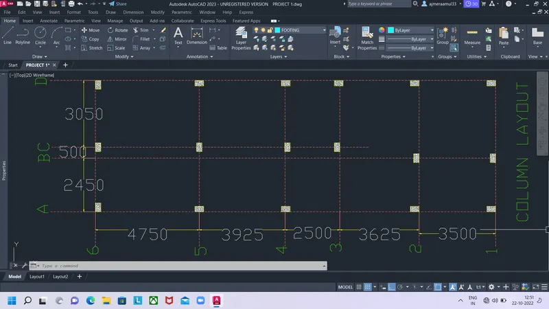
Procedure for columns position layout
Use line tool and draw a rectangle with a length of 18300
And with a breadth of 6000
Select the line type dash llinetype those lines
Give a offsets to a line 6000 length with a distance of 3500,3625,2500,3925,4750
And extend the line at a some distance to indicate the line with a numbers 1,2,3,4,5,6
Now give a offsets to a line 18300 length with a distance of 2450,500,3050
And extend the line at a some distance to indicate the line with a alphabets A,B,C,D
Now draw a columns with a size of 250*400 by using rectangle tool at points A1,A2,A4,A5,A6,B1,B2,C3,C4,C5,C6,D1,D2,D3,D4,D5,D6
And hatch the column in concrete pattern
Now by using DIMLIN command and DIMCONTINUE command give the dimensions between those lines
Result:
2.
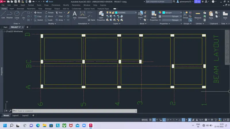
Procedure for beam layout drawing:
Copy the column layout drawing
And draw te beams by following the columns position in the drawing by using line tool
The beam width is given as 400
Draw a continues beam from point A1 to A6 and D1 to D6
Draw a beams from point A6 to D6,A5 to D5,A4 to D4,C3 to D3,A2 to D2,A1 to D1
Next beams are drawn from B1 to B2,C3 to C6 points
Result:-
3.
Procedure for footing plan drawing
Now copy the column layout drawing
Give the offset of 900 for columns positions at A1,A2,A3,A4,A5,A6,D1,D2,D3,D4,D5,D6
Give offset of 700 for interior columns position at B1,B2,C3,C4,C5,C6
Specify the suitable colour to those footings
Result:
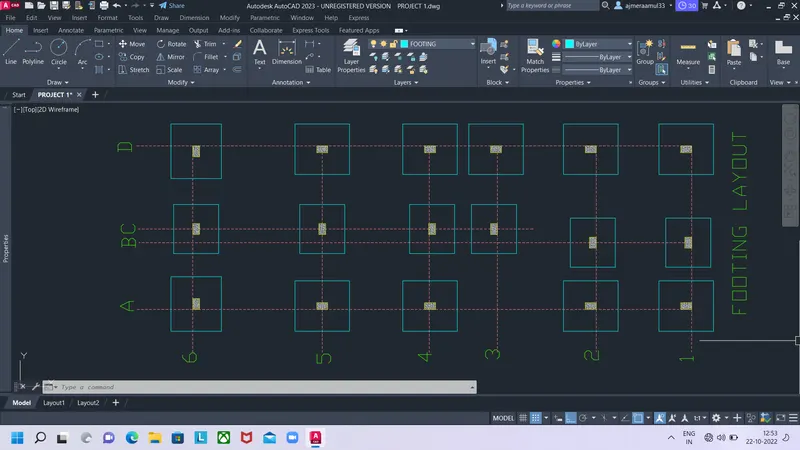
Overall result for architectural drawing and structural drawing for residential building of G+1 floor drawn by using AutoCad