Creating Architectural and Structural model with 3D rendering using REVIT
AIM : Creating Architectural and Structural model with 3D rendering using REVIT
Introduction:
Revit is a one of Building Information Modelling software for architects, landscape architects, structural engineeers, mechanical, electrical and plummbing(MEP) engineers, designers and contractors. Revit supports a multidiscipline design process for collaborative design. it used to make a coceptual design & visualization of the building or a project. Its powerful tools lets us to use the intelligent model-based process to plan, design, construct and manage buildings and infrastructure.
The software was developed by Charles River Software, founded in 1997, renamed Revit technology corporation in 2000, and acquired by Autodesk in 2002. The software allows todesign a building and structure and its components in 3D, aannotate the model ith 2D drafting elements, and access building inforation from the building model's database.
Revit is 4D building infortion modelling capable with tools to plan and track variousstages in the building's lifecycle, from concept to construction and later maintenance and / or demolition.
Question 1) Select the type of structure you want to build from one of the three below:
a. Multi-Unit Residential Apartment
b. Office Buildings
c. School
Ans : i want to build an office building , it is located in Nellore,near the highway.
Question 2) Assume reasonable assumptions for geographic and location details for your project modeling. Based on assumptions and type of structure selected identify the modeling requirements from NBC
Ans :
The geographical and location details for my project modelling,assuming the reasonablr assumptions based on selected identify the modelling requirements from NBC.
- the building comes under the business building ( Group-F) category and it could be located in end of the city.
- The project is located in the highway nearest.
- The road width of this project is 21 meters ,that is hoghway of three line road.
- The height, area limitation and safety measure are followed by the NBC.2005.
- This project height is 10 m, the height of the building should not exceed 1.5 times the width of the road.
- In case of building height is not exceed, so it is suitable for construction.
Question 3) Using the structural model, include the following components based on the type of structure selected
a. Foundation – Isolated / Wall/Matt Foundation
b. Columns
c. Beams Connected to Columns
d. Roof Framing/ Truss
e. Floor / Decks
f. Floor Openings for Elevators and Stairs
Ans :
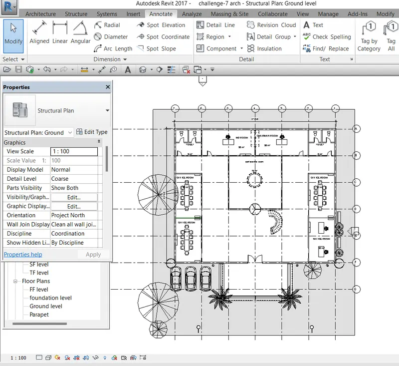
the above mentioned components are drawn in the structural model.
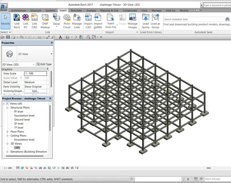
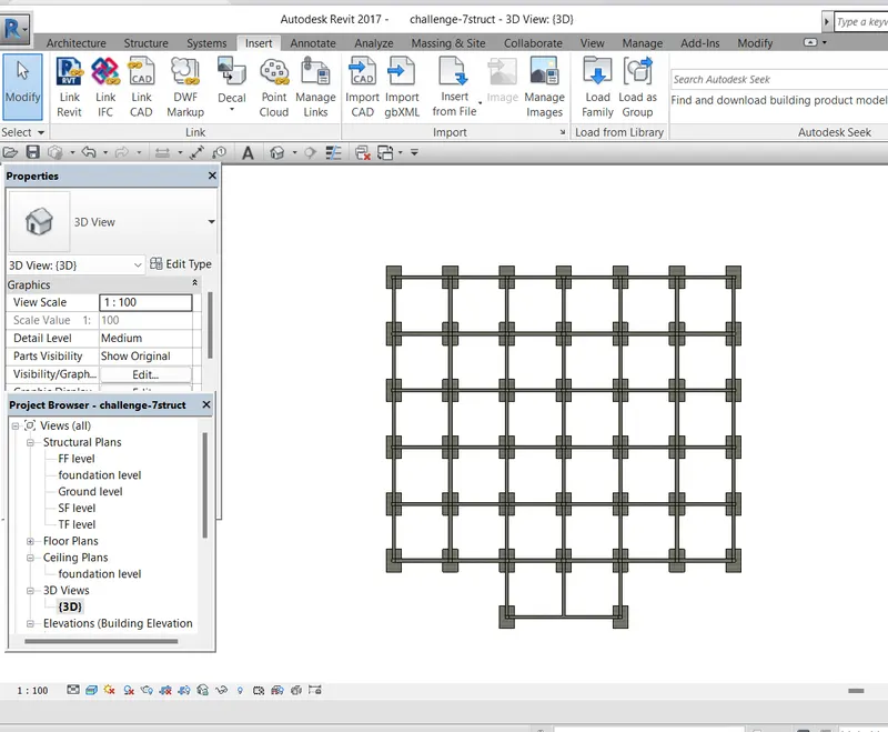
Question 4) Using the architectural model, include the following components based on the type of structure selected
a. Wall Layout with appropriate material and finishing
b. Exterior façade with fancy finish
c. Interior partition walls to size rooms
d. Components to add details to a room ( Desk, Chair, Lighting, Plumbing fixtures)
e. Add components such as stairs Elevators
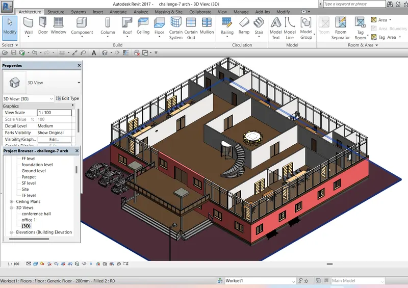
f. Have at-least one side of the building with curtain walls and glass panels
g. Include interior and exterior lighting fixtures
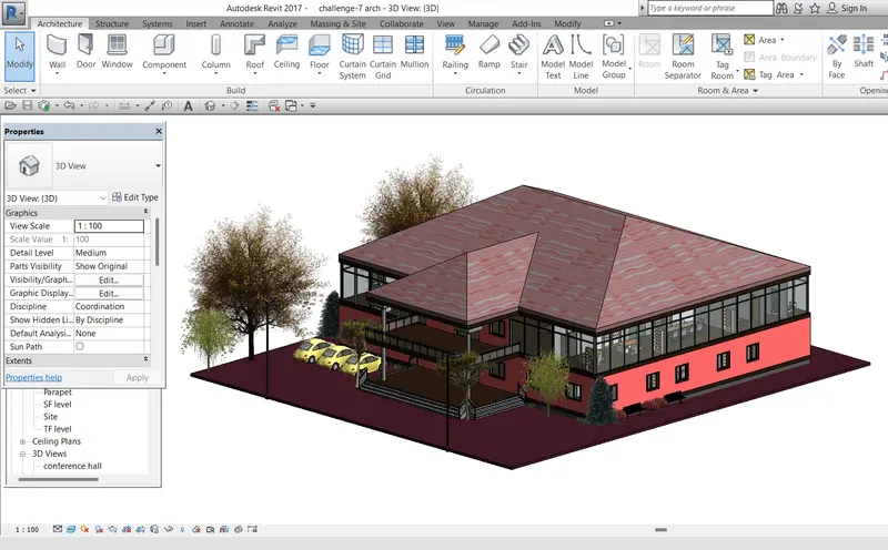
h. Place proper topographic components from outside ( Trees, Parking, Plants) to add details to the model
Ans :
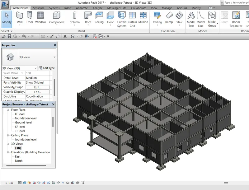
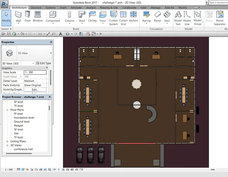
the above mentioned components are drawn in the architectural model.
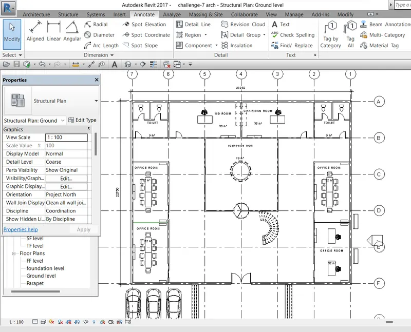
Questione 5) Provide a set of drawings in an architectural and structural model to list the following details with categories and appropriate sheet templates included
a. Floor Plans with Annotations
b. Elevations
c. Sections
Ans :
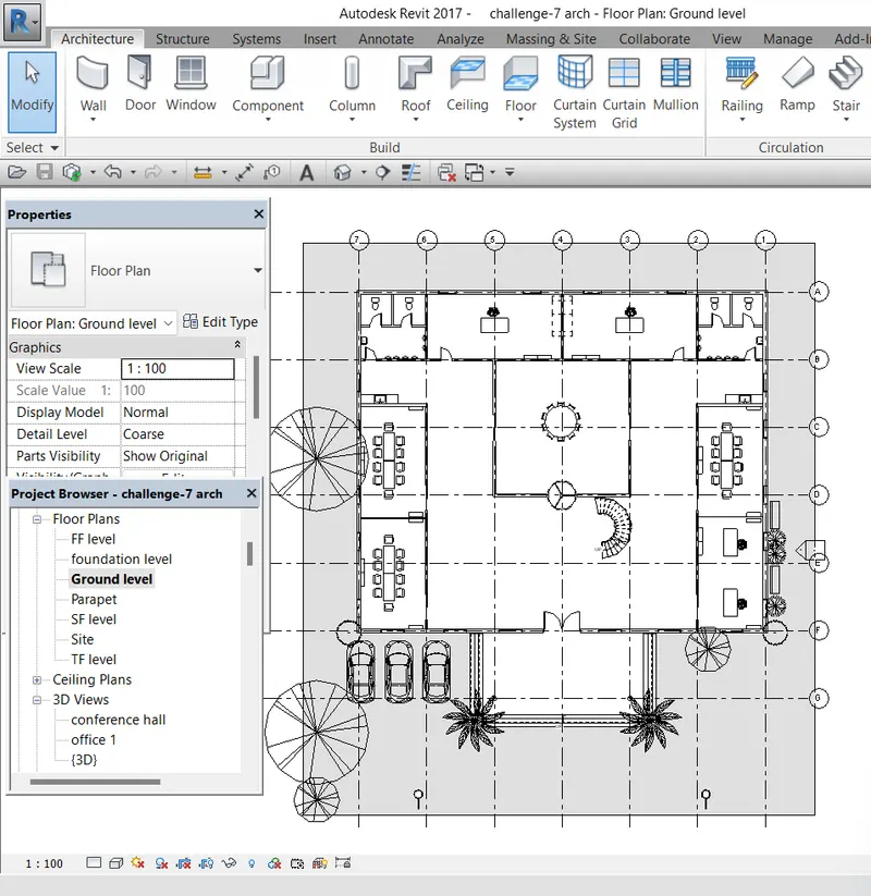
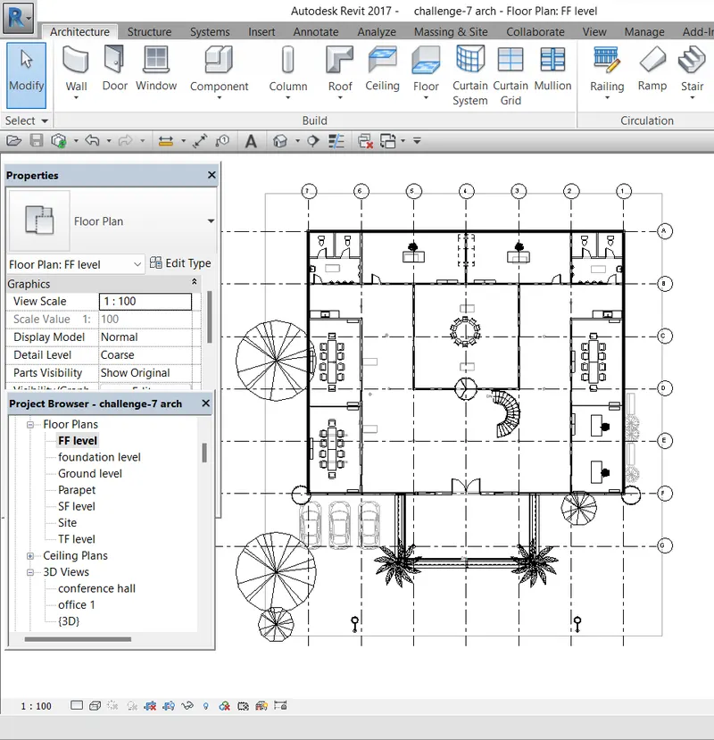
FLOOR PLAN :
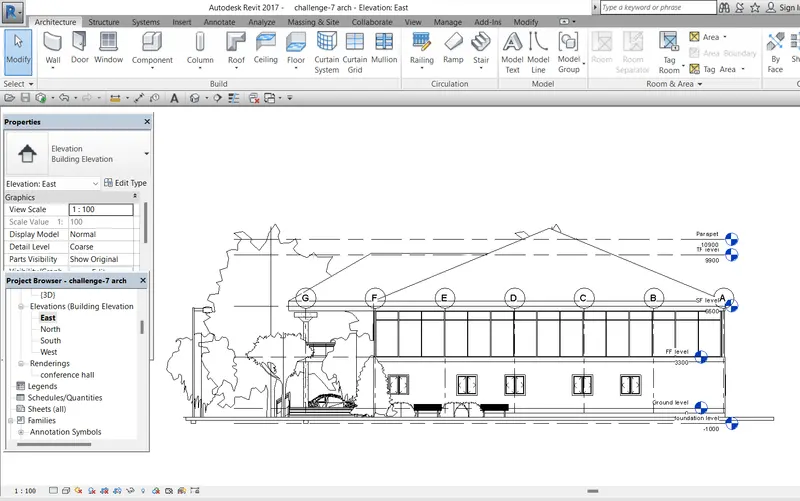
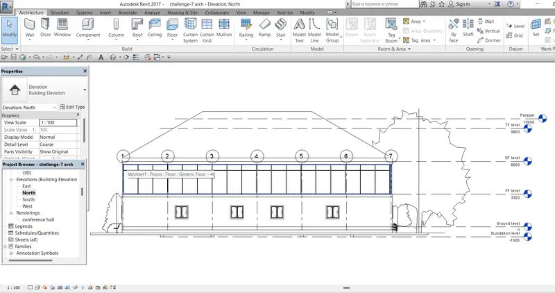
ELEVATIONS :
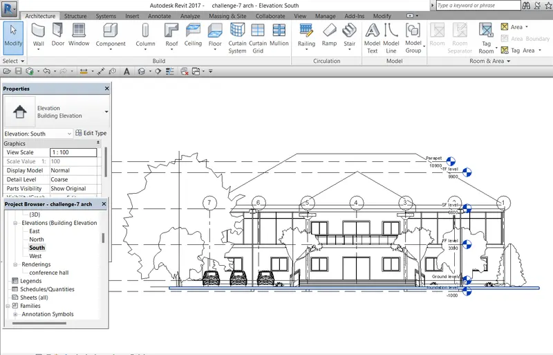
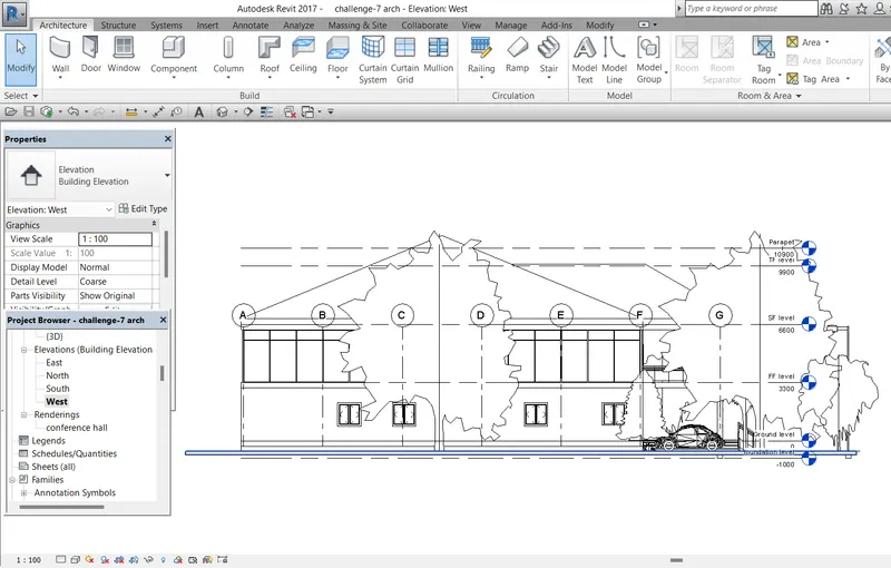
Sections :
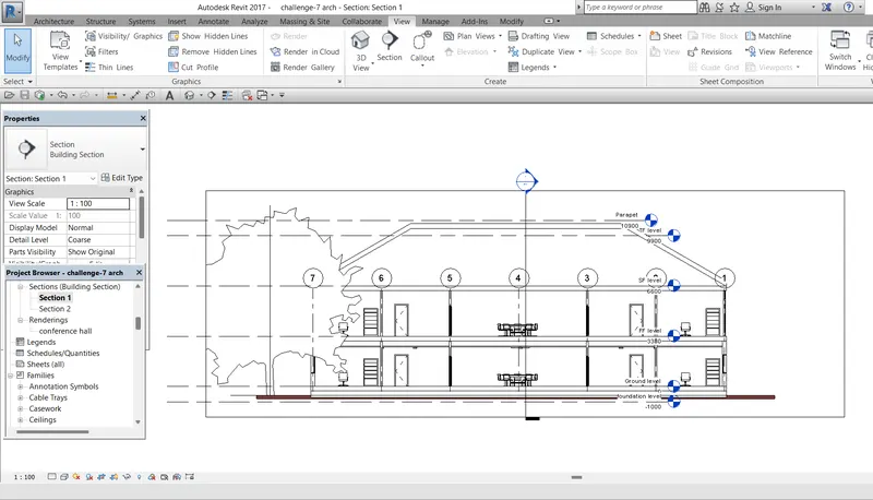
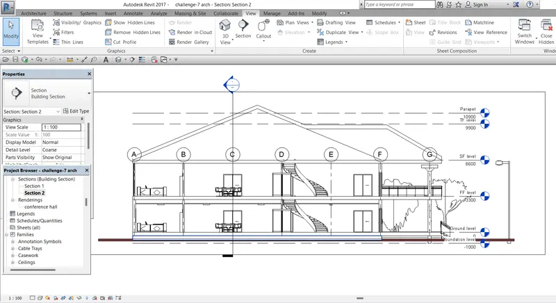
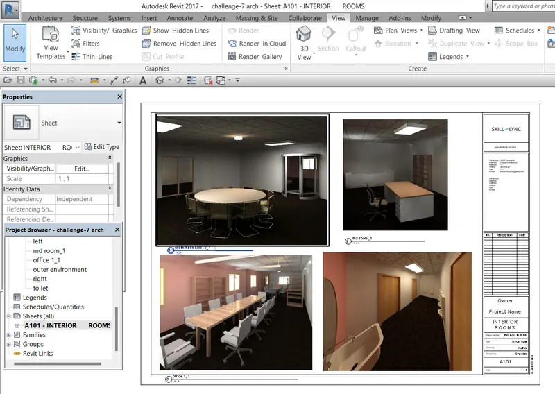
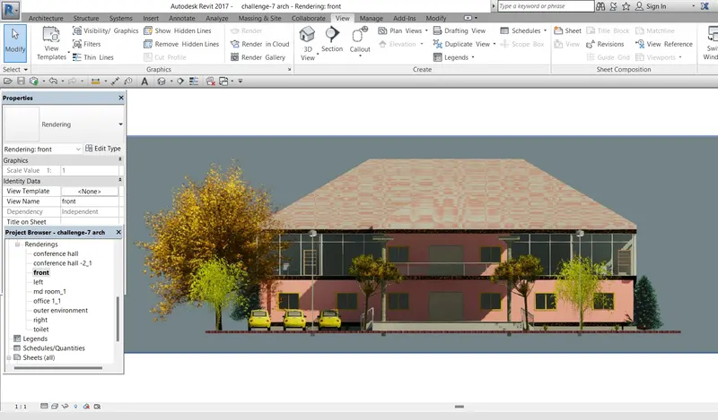
Question 6) Using the Rendering settings, Render images of the 3D model produced and include the rendered images to the drawing sheets
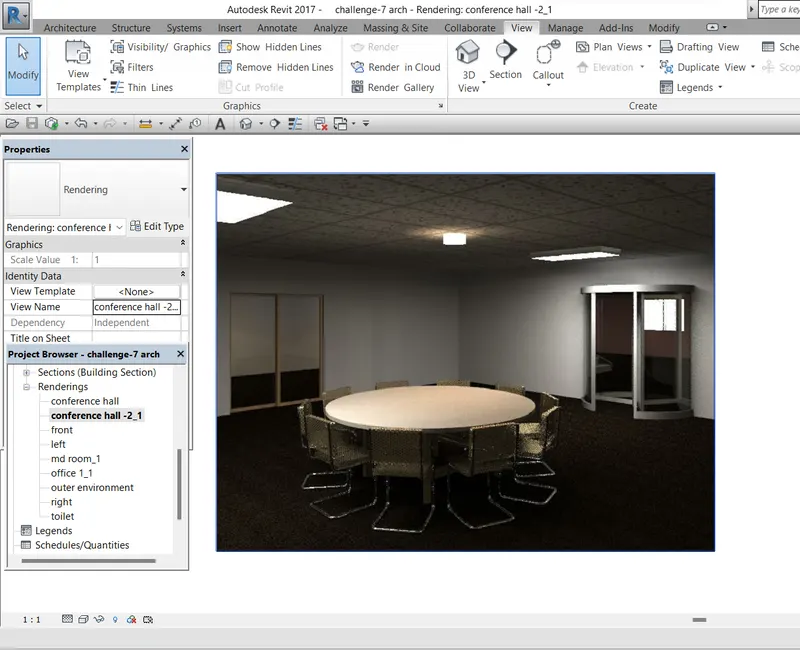
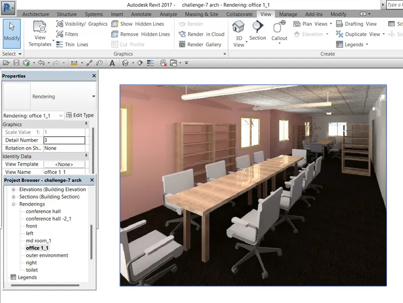
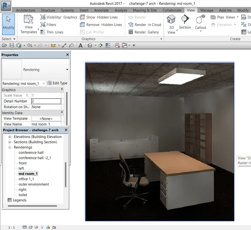
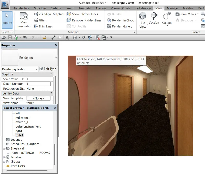
a. Rendering from interior rooms
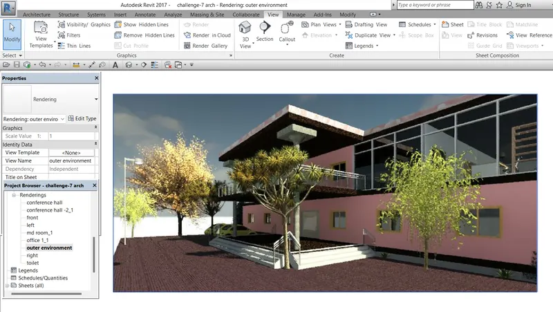
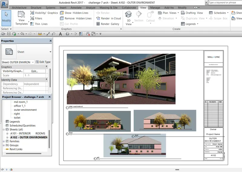
b. Rendering from out showing topographic features
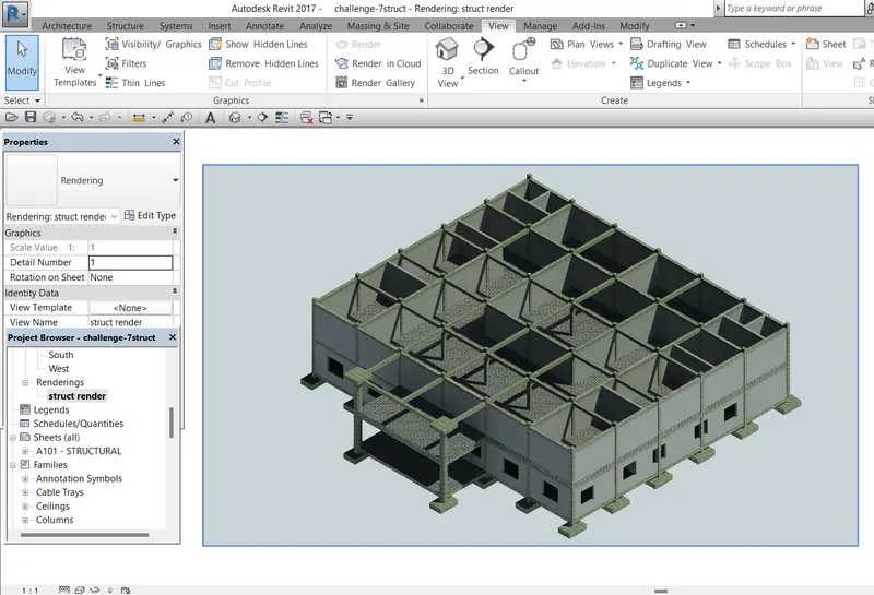
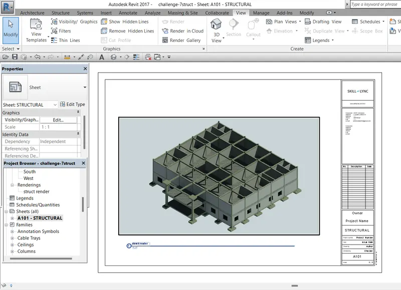
c. Rendering through structural framing
Ans :
- open the revit architecture template then goto view tab.
- click on camera create a view of a room .
- then again go to view tab select the render option, then save the render image to the project.
a. Rendering from interior rooms :
b. Rendering from out showing topographic features :
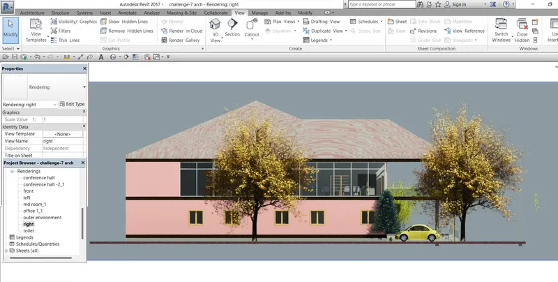
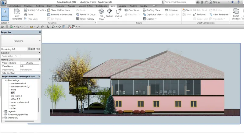
c. Rendering through structural framing :
Question 7) Print the set of drawing sheets created and submit the drawings from the architecture and structure model.
Ans :
- print the drawing sheets by using print option and save the templete.
Result :
- The above Taken project were completed and the answers and set of drawings are uploaded above with the specified ,related images.