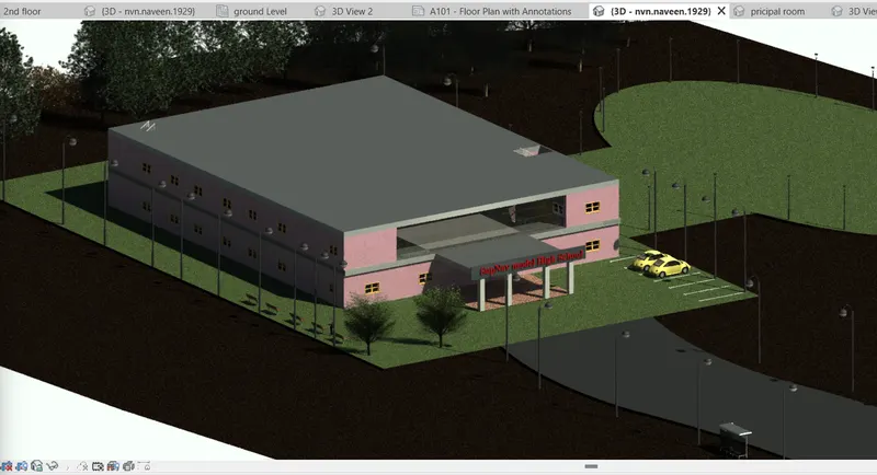
Creating Architectural and Structural model with 3D rendering using REVIT
REVIT PROJECT
Creating Architectural and Structural model with 3D rendering using REVIT
AIM: To Creating Architectural and Structural model with 3D rendering using REVIT
1Q) Select the type of structure you want to build from one of the three below:
a. Multi-Unit Residential Apartment
b. Office Buildings
c. School
The above follwing I select the school building to model
Introduction :
School building means a building housing classrooms, laboratories, dormitories, athletic facilities, or related facilities operated in connection with a school. School building means a school or program identified by its Basic Educational Data System (BEDS) code, as determined by the commissioner.
2Q) Assume reasonable assumptions for geographic and location details for your project modeling. Based on assumptions and type of structure selected identify the modeling requirements from NBC.
Answer:
The National Building the assumptions taken are:
PART 3 DEVELOPMENT CONTROL RULES AND GENERAL BUILDING REQUIRMENTS page 25
Assume Primary schooll(class 1 to 5) for every 5000 population
Strength of the school 500 students
Area per school 0.40 ha
School building area 0.30 ha 3000m2
Play field area 0.10 ha-1000m2 (with a minimum of 18 m 36 m to be ensured for effective play)(which is inclusive of the limited parking requirement for functional uses)
NOTE: The schools should be inclusive providing education to all children including those with disabilities. However it may be required to have exclusive schools in case of certain disabilities, such is speech hearing, sight and multiple disabilities.
PART 3 DEVELOPMENT CONTROL RULES AND GENERAL BUILDING REQUIRMENTS page 46
12 REQUIREMENTS OF PARTS OF BUILDINGS
Plinth:
Main Buildings:
The plinth or any part of a building or outhouse shall be so located with respect to the surrounding ground level that adequate drainage of the site is assured. The height of the plinth shall be not less than 450 mm from the surrounding ground level.
Interior Courtyards and Covered Parking Every interior courtyard shall be raised at least 150 mm above the determining ground level and shall be satisfactorily drained.
Habitable Rooms:
Height:
The height of all rooms for human habitation shall not be less than 2.75 m measure the surface of the floor to the lowest point of the ceiling (bottom of slab). In the case of pitched roof, the average height of rooms shall not be less than 2.75 m. The minimum clear head room under a beam, folded plates or eaves shall be 2.4 m. In the case of air conditioned rooms, a height of not less than 2.4 m measured from the surface of the floor to the lowest point of air conditioning duct or the false ceiling shall be provided.
Size:
The area of habitable room shall not be less than 9.5 m2,where there is only one room with a minimum width of 2.4 m.
Kitchen:
Height:
The height of a kitchen measured from the surface of the floor to the lowest point in the ceiling (bottom slab) shall not be less than 2.75 m. except for the portion to accommodate floor trap of the upper floor.
Size:
The area of a kitchen where separate dining area is provided, shall be not less than 5.0 m2 with a minimum width of 1.8 m. Where there is a separate store, the area of the kitchen may be reduced to 4.5 m2
A kitchen which is intended for use as a dining area also, shall have a floor area of not less than 75 m2 with a minimumn width of 2.1 m
Other Requirements:
Every room to be used as kitchen shall have
unless separately provided in a pantry means for the washing of kitchen utensils which shall fead directly or through a sink to a grated and
trapped connection to the waste pipe
an impermeable floor:
a flue, if found necessary
a window or ventilator or opening
Bathrooms and Water-Closets:
Height:
The height of a bathroom or water-closet measured from the surface of the floor to the lowest point in the ceiling (bottom of slab) shall not be less than 2.1 m.
Size:
The area of a bathroom shall not be less than 1.8 m2 with a minimum width of 1.2 m. The floor area of watercloset shall be 1.1 m2 with a
minimum width of 0.9 m.
If bath and water-closet are combined, its floor area shall not be less than 2.8 m2 with a minimum width of 1,2 m
Other Requirements:
Every bathroom or water-closet shall be so situated that at least one of its walls shall open to external air
not be directly over or under any room otherthan another water-closet, washing place, bath or terrace, unless it has a water-tight floor.
have the platform or seat made of water-tight
non-absorbent material,
be enclosed by walls or partitions and the surface of every such wall or partition shall be finished with a smooth impervious material to a height of not less than 1 m above the floor of such a room:
be provided with an impervious floor covering sloping towards the drain with a suitable grade and not towards Verandah or any other room. have a window or ventilator, opening to a shaftor open space of area not less than 0.3 m2 with side not less than 0.3 m
No room containing water-closets shall be used for any purpose except as a lavatory and no such toom shall open directly into any kitchen or cooking space by a door, window or other opening Every room containing water-closet shall have a door completely closing the entrance to it
For educational the followingminimum requirements suply Educational Ceiling height 3.6 m for buildings all regions
Boundary Wall
Educational buildings like schools, colleges, including hostels, and other uses of public utility undertakings and strategically sensitive buildings, a height up to 2.4m may be permitted by the Authority
PART 3 DEVELOPMENT CONTROL RULES AND GENERAL BUILDING REQUIRMENTS page 56
Table 8 Minimum Accessibility Provisions in Different Building Occupancies (Clause 13.5)
Educational buildings
Schools, colleges, classrooms, libraries, assembly points, halls, staff rooms, laboratories, play grounds
All teaching/administrative and common areas frequented by staff/students.
In libraries all open book stacks. Few enclosed rooms in library for those with hearing and vision impairments who may need assistance while reading
PART 4 FIRE AND LIFE SAFETY page 59
Life Safety:
A building, which will have only the first floor and is accessible to not more than 20 pupils at any time, may be used for school purposes with the following exceptions:
Exterior walls or parts of walls which are less than 900 mm from adjacent property lines shall have no openings therein.
Classrooms may have only one exit not less than 900 mm wide.
PART 6 STRUCTURAL DESIGN SECTION 8 GLASS AND GLAZING page 53
SAFETY RELATED TO HUMAN IMPACT:
Critical Location
Where any glazing is within 1.5 m above the floor level of a building, it is considered likely to be subjected to hurnan impact and hence, shall comply with the human impact safety requirements of this Section Safety glazing should also be used
where there is danger of falling infill glass material(s) from overhead glazing the danger of falling due to a change in floor level and in case of balustrades, stairs and floors
3) Using the structural model, include the following components based on the type of structure selected
a. Foundation – Isolated / Wall/Matt Foundation
b. Columns
c. Beams Connected to Columns
d. Roof Framing/ Truss
e. Floor / Decks
f. Floor Openings for Elevators and Stairs
AIM: To Model the structural elemets
Procedure :
- First open the revit software
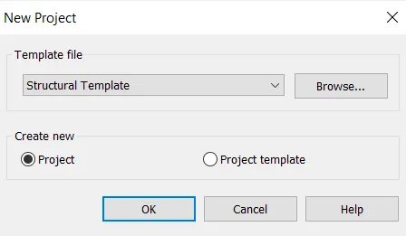
- Click on structural template.
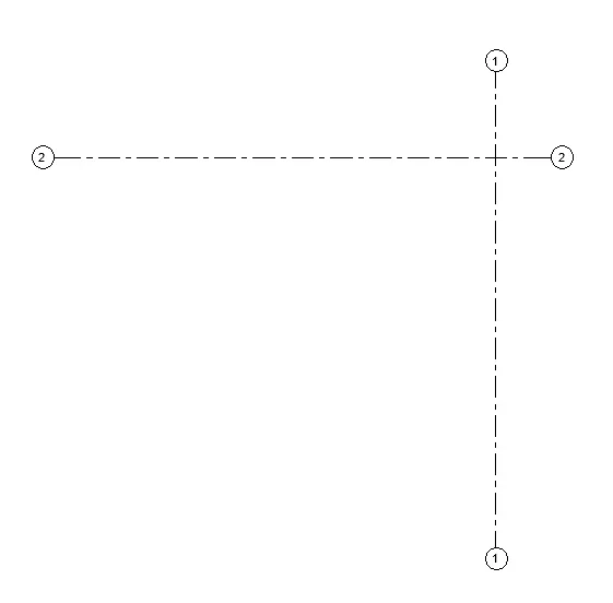
- Again draw the grips
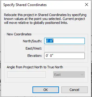
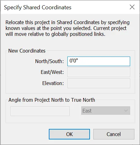
- Go to manage tab>project coordinates>shared coordinates.
- In the north/south type 0'0".
- In east/west type 0'0".
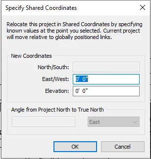
To create project base points:
- Now click VG command
- Then the VG dialog will popup
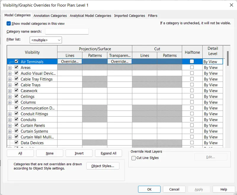
- Scroll down then select the site option
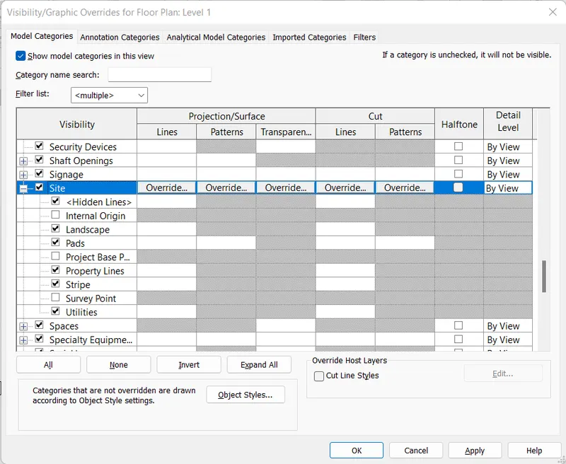
- Then click on the Project base points Then we will get symbol in project
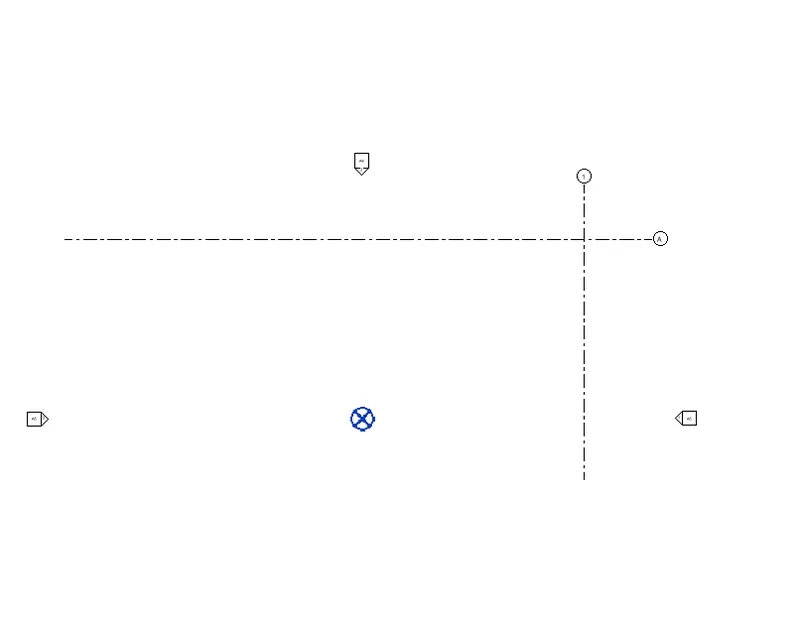
- Now create more grips as our plan
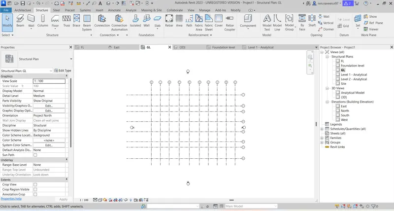
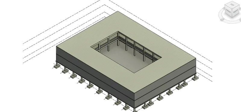
- Now change the level to foundation level and then click on the structure tab in That select the isolated option and select the footing sizes we need then paste at required location
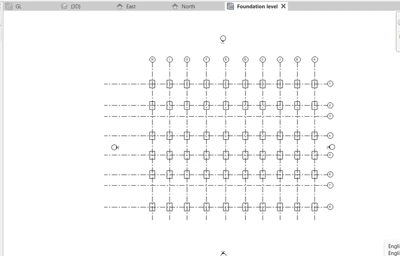
- From the north direction it will visible like
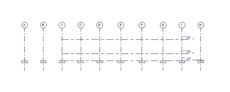
- Now select the column option in the structure tab then paste on the footings
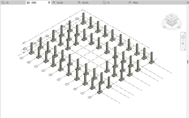
- Now clcik on the beam option then select the sizes and locate at required possition
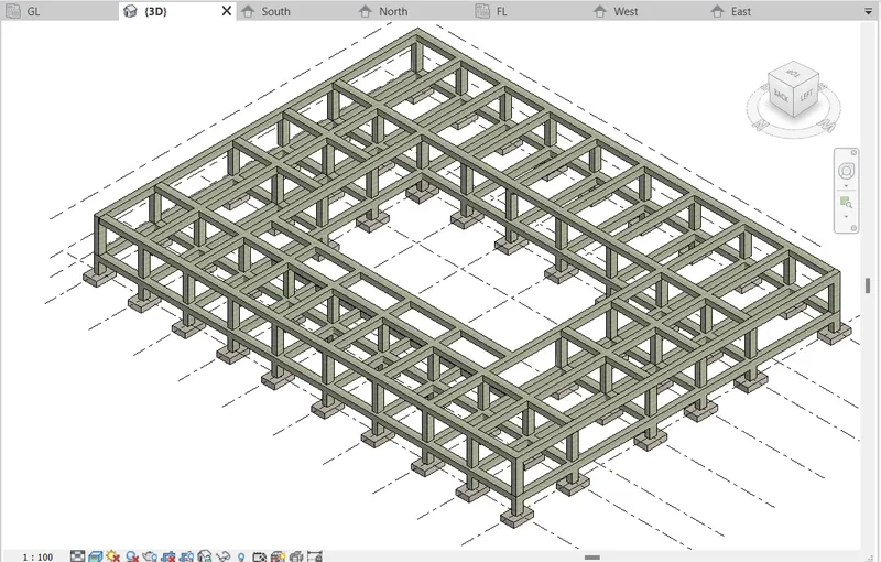
- Now select the structure tab and select flooring option then assign floor
- And select the columns and beams then copy and paste at 2nd floor
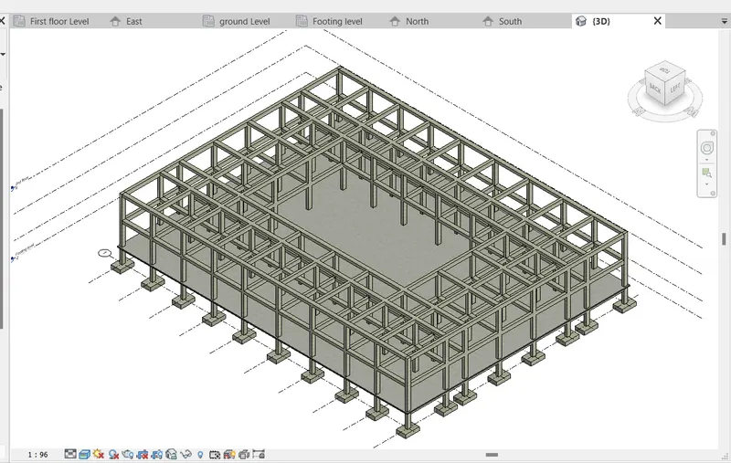
- Now create slabs in the structure tab and in openings tab select shaft option then create boundary click on ok
- Then the shaft opening will be created.
- In the stair case position also we have to create shaft opening
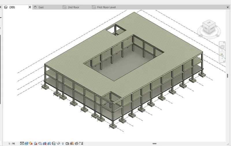
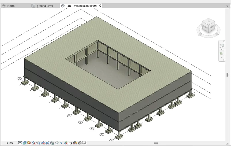
- Now create walls by walls option
4) Using the architectural model, include the following components based on the type of structure selected
a. Wall Layout with appropriate material and finishing
b. Exterior façade with fancy finish
c. Interior partition walls to size rooms
d. Components to add details to a room ( Desk, Chair, Lighting, Plumbing fixtures)
e. Add components such as stairs Elevators
f. Have at-least one side of the building with curtain walls and glass panels
g. Include interior and exterior lighting fixtures
h. Place proper topographic components from outside ( Trees, Parking, Plants) to add details to the model
ANS:
- Open a architectural template in revit software and save it as residential building-arch001.
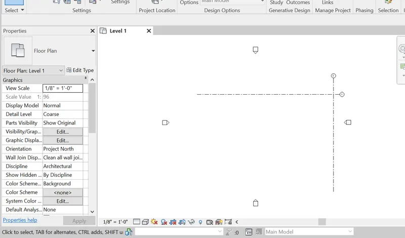
- Then draw the grid lines and specify coordinates as 0'0" for both horizontal and verital grids lines.
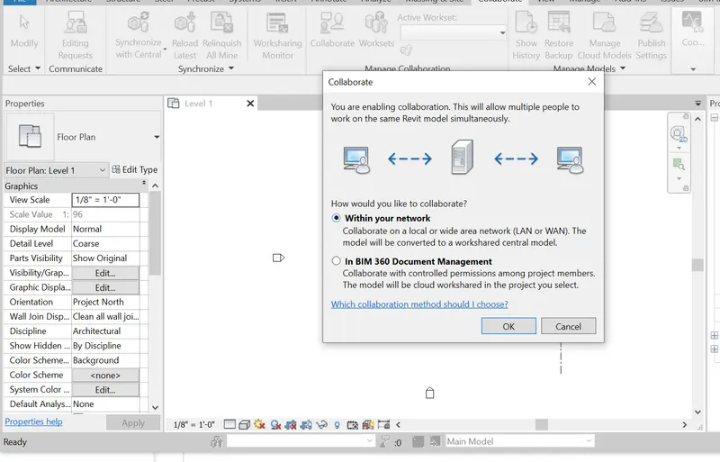
- Click the collaborate and save the project.
-
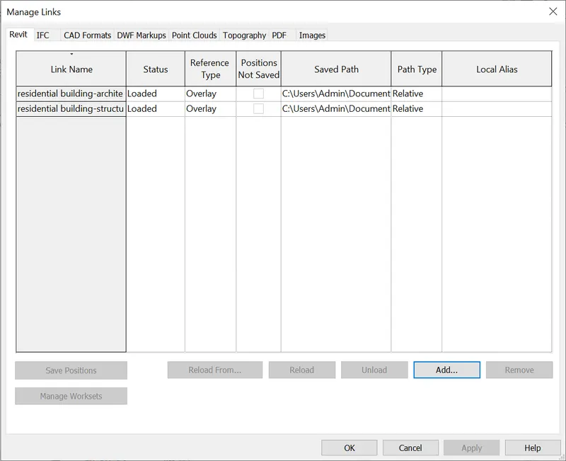
- Select the acquired coordinates and set the links to the current coordinates.
- Now create the grips and level reffering as previously linked structural template.
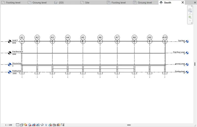
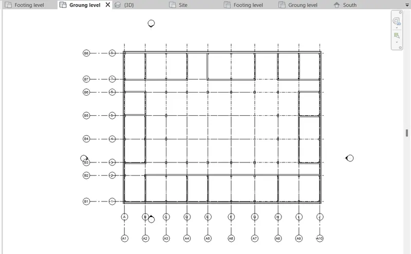
- Now go to the manage tab select the manage link option then unlink the structure template
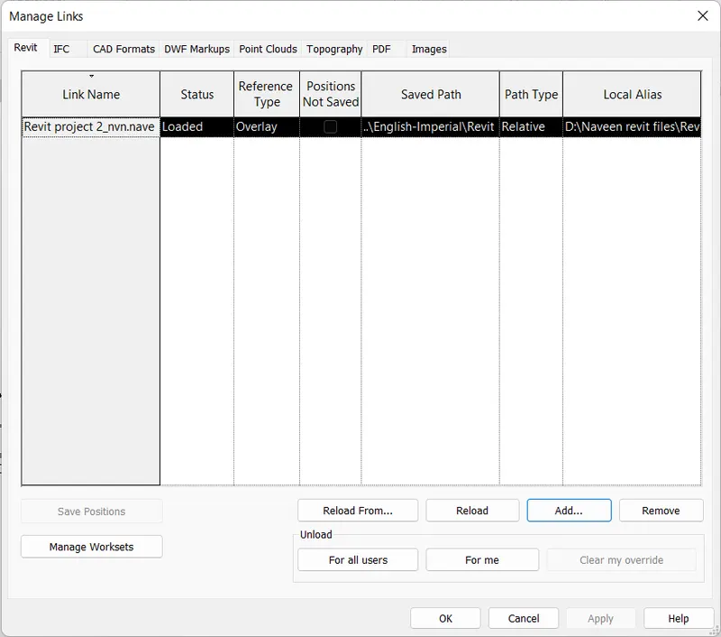
- Now the grips and levels are created in the architecture tab
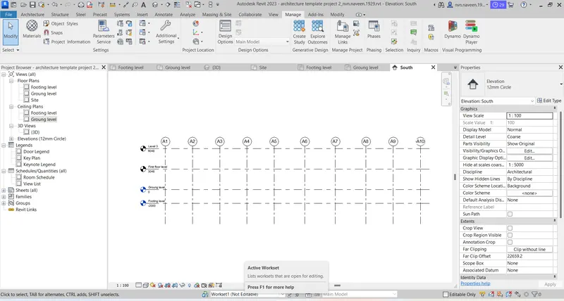
- Now go to the ground floor plan
- select the wall and modify the material that for finisher
- asign to grips as per plan
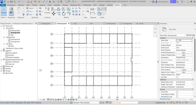
- And select the floor option create a floor and also asign the doors and windows
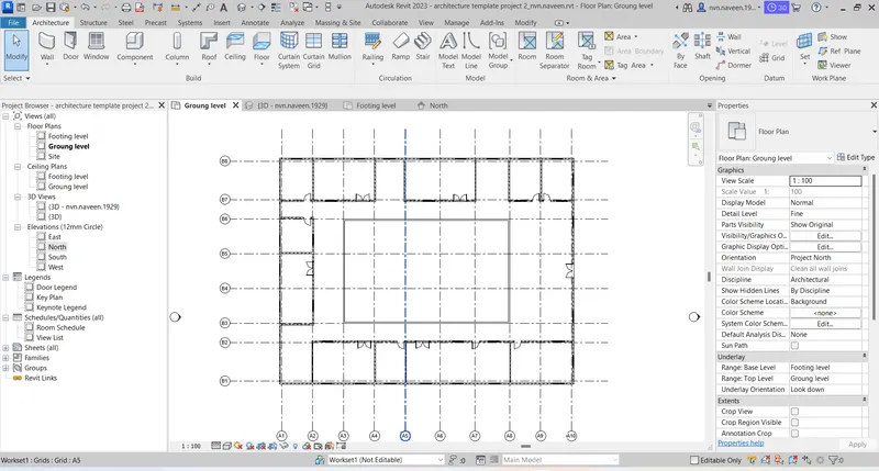
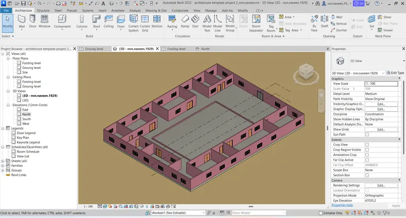
- Go to the component option load families
- The asign the tables and chair in the class rooms
- Add furniture in the office room
- In the balcony the architechture columns created
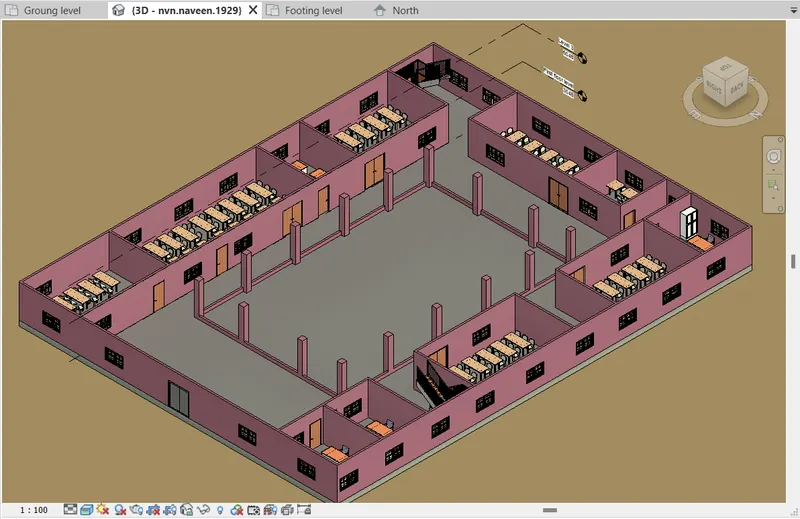
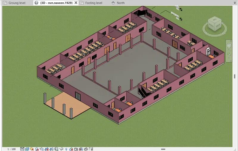
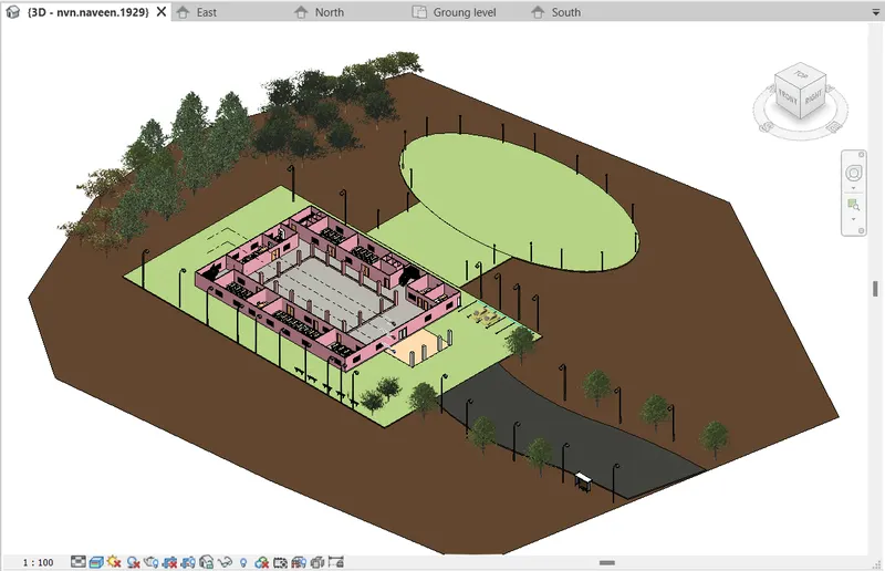
- Now go to massing & Site Tab and select Toposurface option and create the toposuface
- And also select the site comoponents option to create the trees and benches, cars etc..
- Then select the parking components option to create the parking bays
- And aslo create the play ground by using floor option.
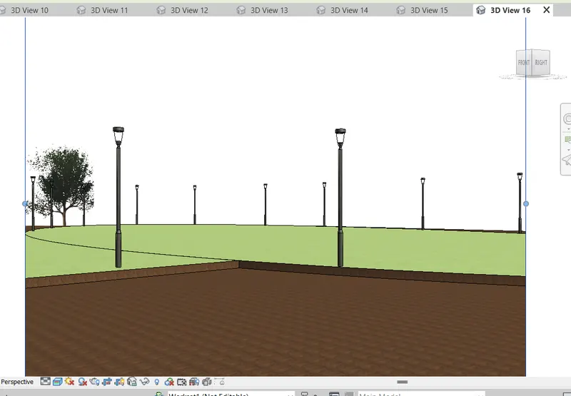
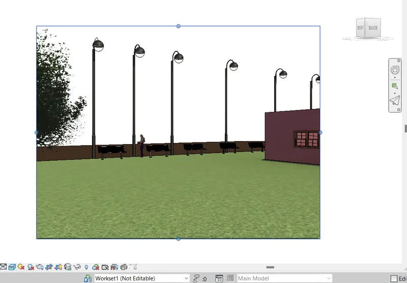
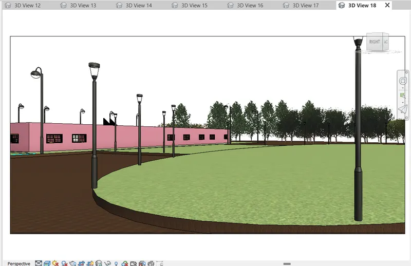
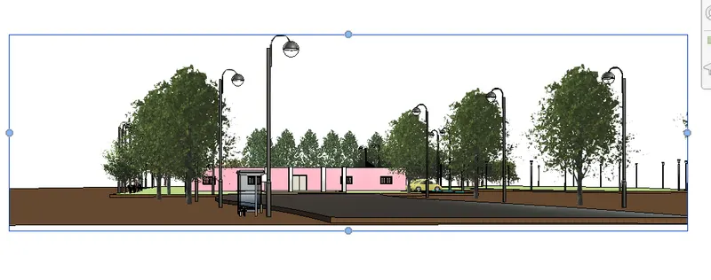
- Create the lighting components
5) Provide a set of drawings in an architectural and structural model to list the following details with categories and appropriate sheet templates included
a. Floor Plans with Annotations
b. Elevations
c. Sections
Ans :
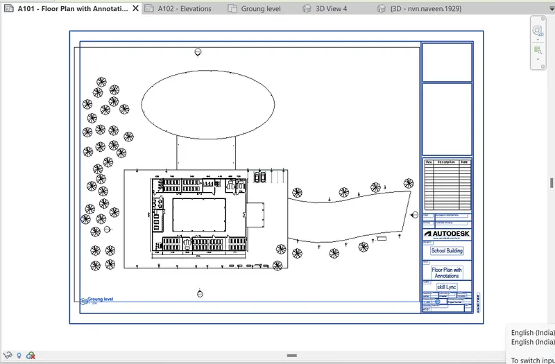
a). Floor Plans with Annotations
- Go to the annotate tab then give the annotation to the floor plan
- Then go to the view tab then select the sheet option
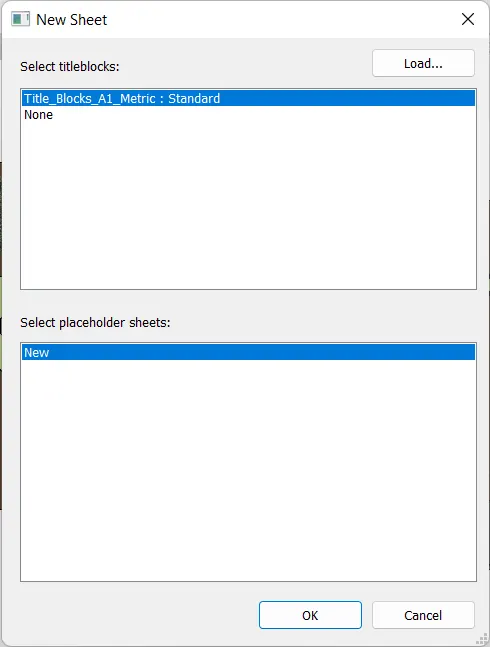
- Create thea a new sheet
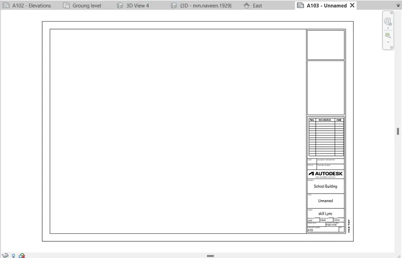
- Rename and provide details to the sheet
- In the view tab select the plan views option then select the ground floor plan
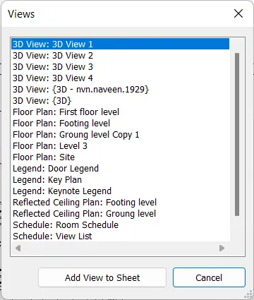
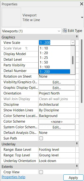
- Scale the selected view then asign in the sheet
b). Elevations
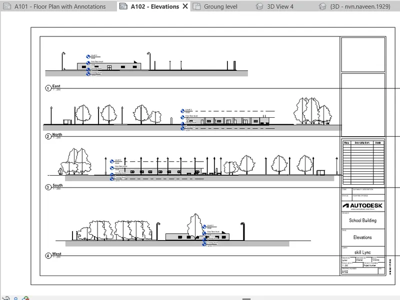
- Now again select sheet then create a new sheet and rename it
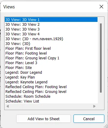
- Then go to the views option select the the elevations and scale it and then fit in the sheet
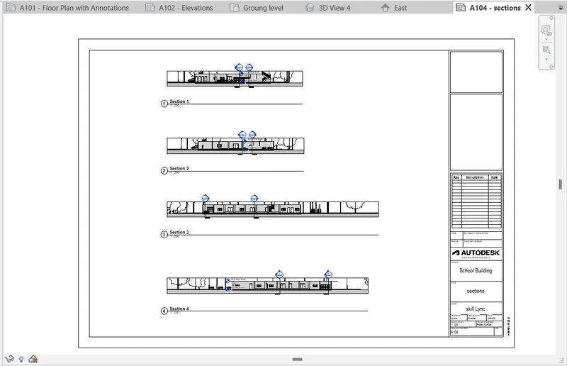
C. Sections :
- Now go to the view tab and select sheet option then create a new sheet and rename it
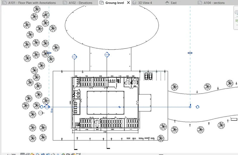
- Select the ground floor plan and click on the view tab
- In that select the section option then create a sections
- Select the previous sheet
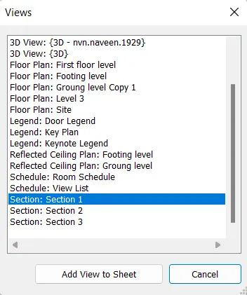
- Now go to the view tab then select the view option then select the section and then asign to the sheet
6) Using the Rendering settings, Render images of the 3D model produced and include the rendered images to the drawing sheets
a. Rendering from interior rooms
b. Rendering from out showing topographic features
c. Rendering through structural framing
Ans :
a). Rendering from interior rooms
- Go to the ground level plan then go to the view tab select the 3d View option drop down it ans select the camara option
- provide the camera at every room
- Pricipal room
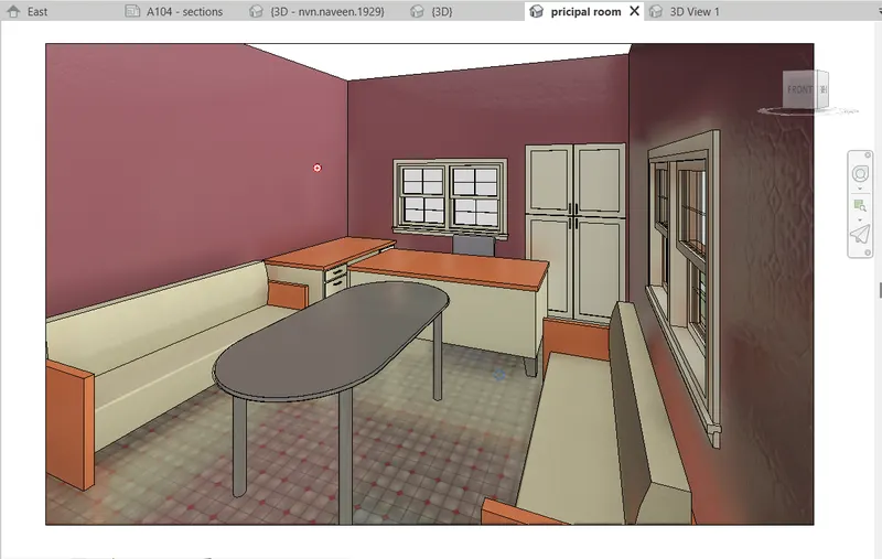
- Staff room
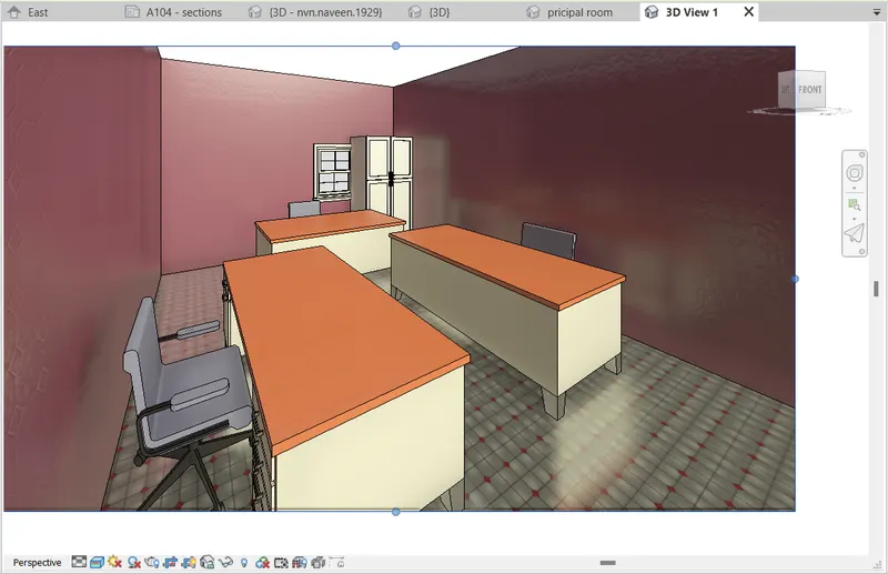
- stair case
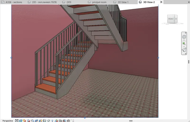
- Toilet room 1
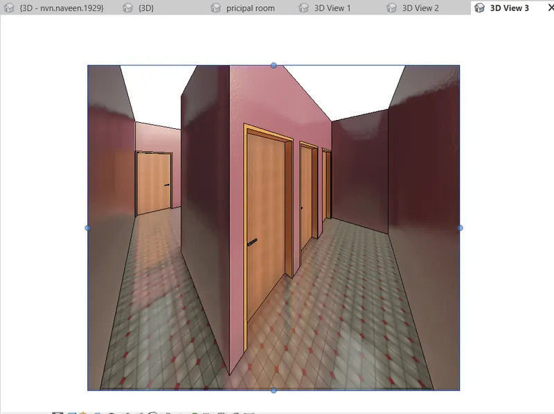
- Class room 1
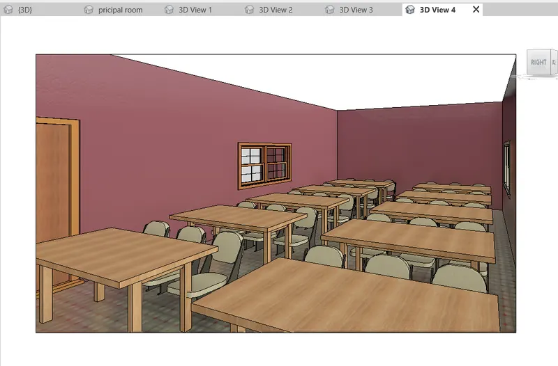
- Class room 2
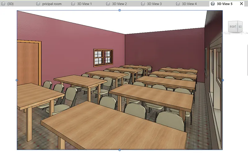
- Toilet room 2
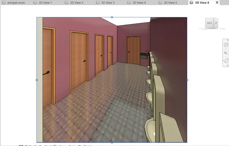
- Lab room
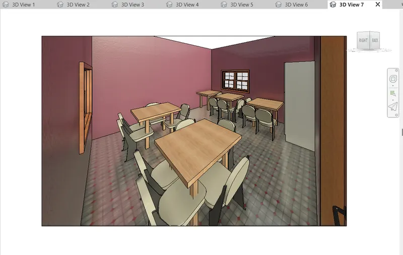
- Library
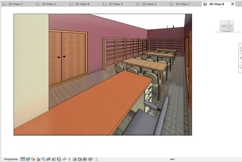
- Class room 3
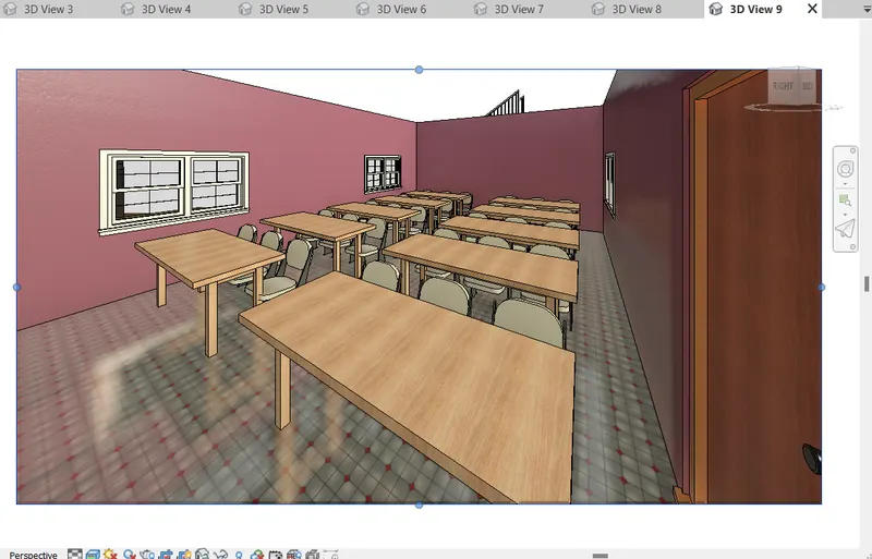
- Staff room 2
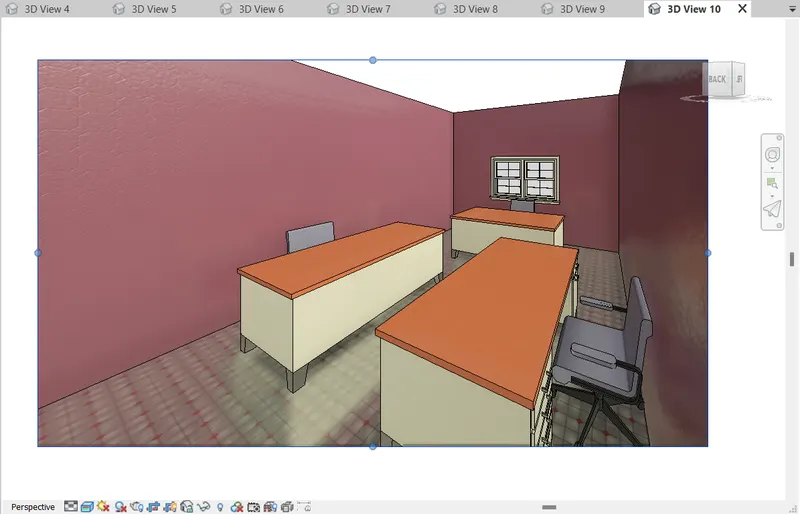
- Class room 4
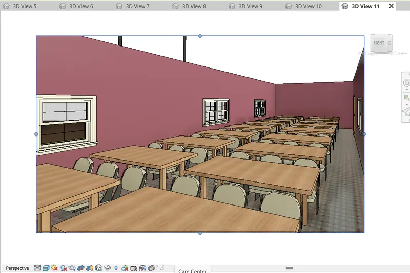
- Class room 5
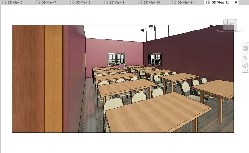
- Balcony
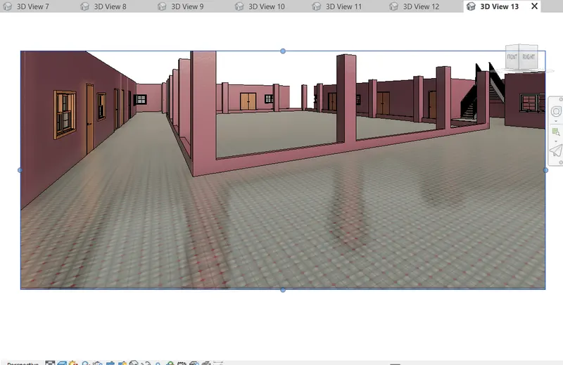
- Front elevation
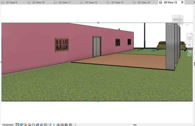
b. Rendering from out showing topographic features
- Ground
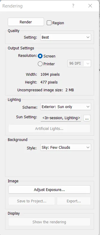
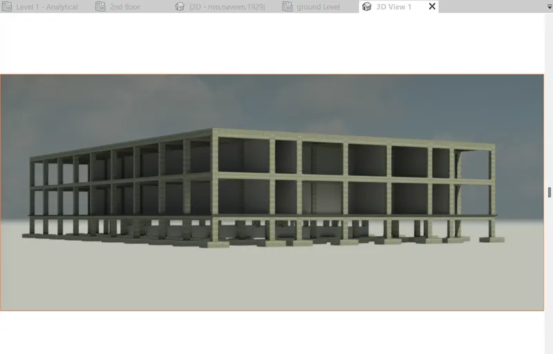
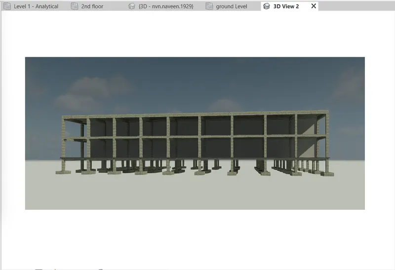
c). Rendering through structural framing
- Open the structure modeling
- Go to the view option the create a camera view
- Then in the render option click on render
7) Print the set of drawing sheets created and submit the drawings from the architecture and structure model
Ans :
- In the tool bar there is a print option
- First open the perticular plan or view to print then click on print option
- The print dialog will open
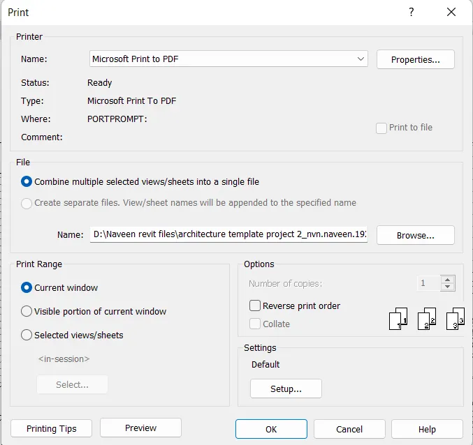
- Now apply all properties as we required then check The print preview
- The print will be done as hard or soft copy.
- Do all views and plans and section and elevations and summit to the copys for architecture and structural engineers
Result: Architectural and Structural model with 3D rendering created by using REVIT