Creating Architectural and Structural model with 3D rendering using REVIT
1) Select the type of structure you want to build from one of the three below:
a. Multi-Unit Residential Apartment
b. Office Buildings
c. School
Aim: To draw a office building as per the NBC guidelines in Revit by combining both Architectural and Structural model and to use collaborate and make the files central and to also use copy/monitor, synchronize options.
2) Assume reasonable assumptions for geographic and location details for your project modeling. Based on assumptions and type of structure selected identify the modeling requirements from NBC
Height of my office building is around 18m i.e., as it is beyond 15 m height it is being governed by provisions laid down in the code
According to NBC 2016, Annexure C clause C-2.3 the area occupied by building in my model is greater than 40 sq.m and plot area of my model is 50 m x 60 m i.e., 3000 sq.m and individual floor area is 30 m x 50 m ie., 1500.
FAR = (1500*4)/3000 = 2
As per table 5 of NBC guidelines for business FAR should be less than 2.9. Hence it follows NBC guidelines.
According to NBC 2016, Annexure C clause C-3.5,
The minimum height of rooms/spaces shall be as follows:
1. Habitable room : 2.6 m
2. Kitchen : 2.6 m
3. Bath/water-closet : 2.1 m
4. Corridor :2.1 m
In my model the room sizing and height of the walls is as per the NBC guidelies
3) Using the structural model, include the following components based on the type of structure selected
a. Foundation – Isolated / Wall/Matt Foundation
b. Columns
c. Beams Connected to Columns
d. Roof Framing/ Truss
e. Floor / Decks
f. Floor Openings for Elevators and Stairs
Aim & Introduction: To include components like foundation, beams, columns, roof trusses, floors, floor openings if any for elevators and stairs in the structural model
Procedure:
1. Open the structural template in revit model
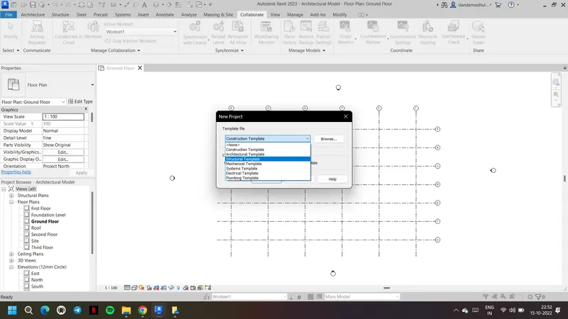
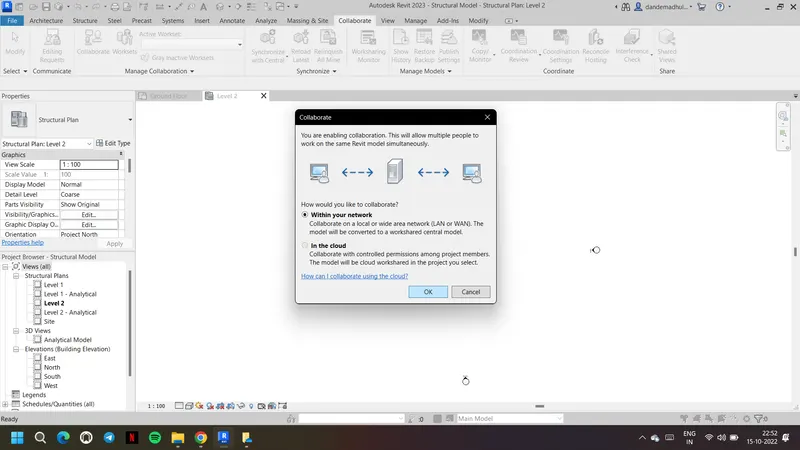
2. Save it as structural model, collaborate it and save it as central model. Also synchronize it
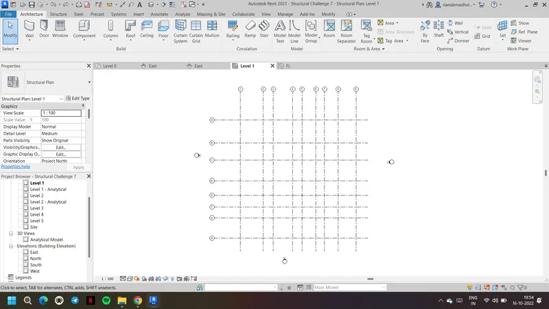
3. Create the grids in the model according to the plan wiht respective offsets
4. Choose grid option and create longitudinal and transverse grids as shown below
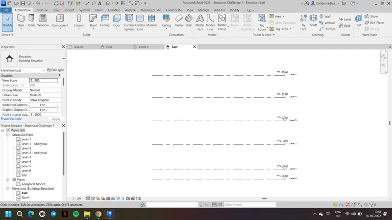
5. Now open the elevation view and create the levels
6. Create foundation level at -1.5m, first level at 4m, second, third and fourth levels at 3.7m and for roof provide 2.5m
7. Now open the foundation level, choose isolated foundation from structure toolbar
8. Place the foundation at respective grids wherevr required as per the office plan
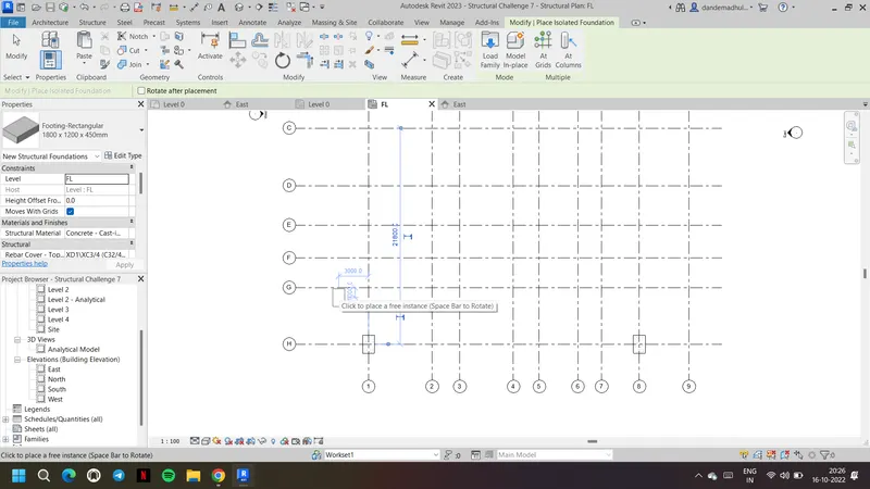
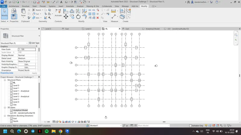
9. Now choose columns and place them on foundation
10. Choose top constraint of the columns as fourth level
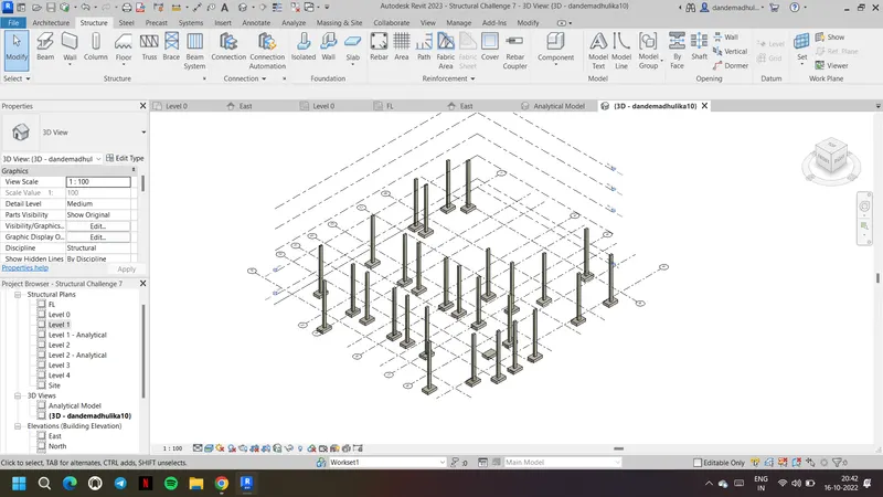
11. Choose the beams and place the beams such that to connect the inserted columns
12. If needed edit the dimensions of the beams and place accordingly with respect to the dimensions of columns
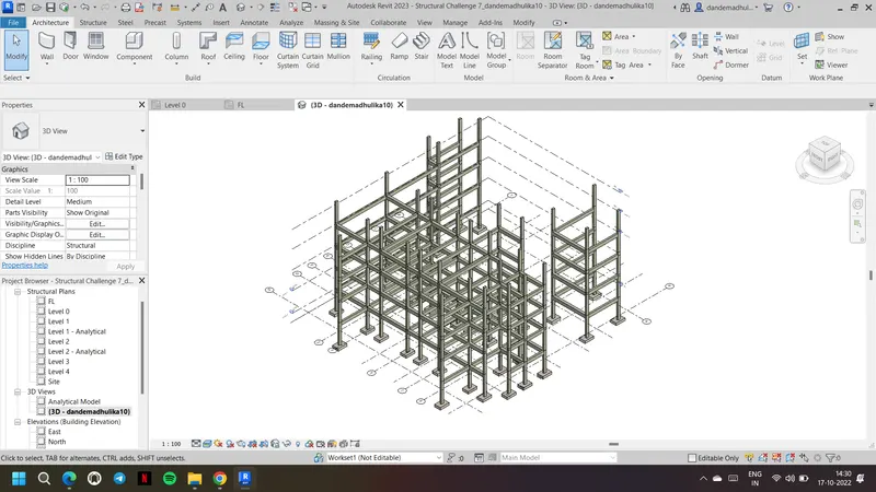
13. Now copy the created beams of ground level and place them in first, second third and fourth levels
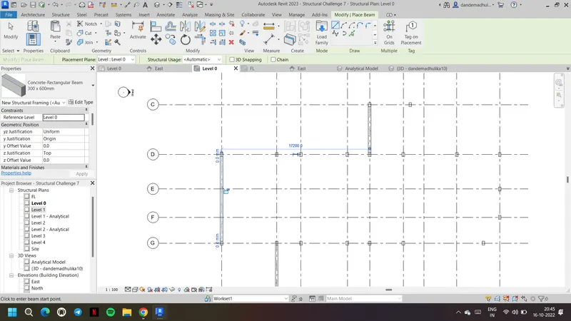
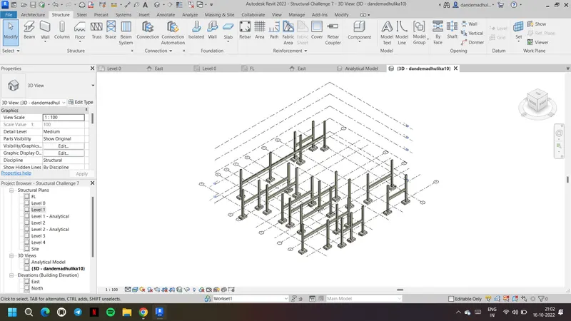
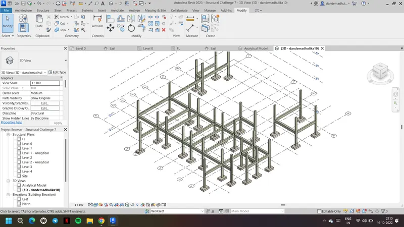
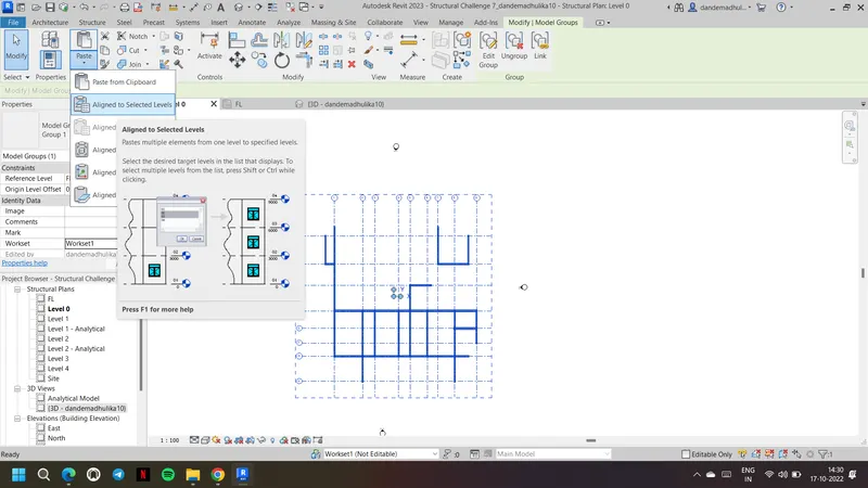
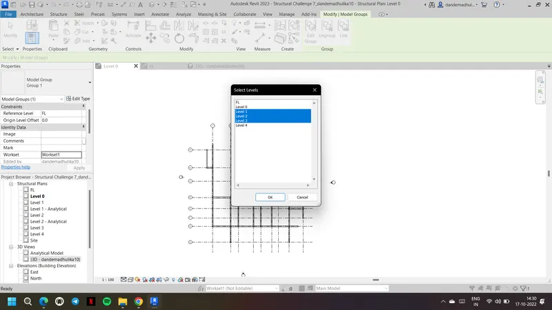
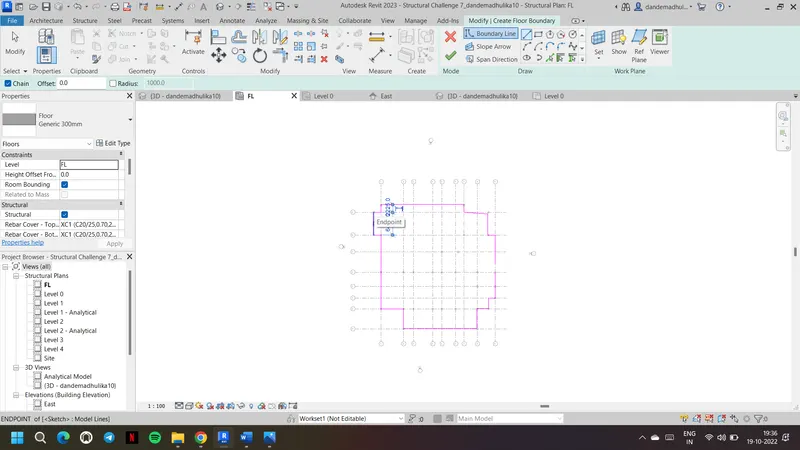
14. Choose the floor from structure toolbar and choosing the pick up line create the floor as shown
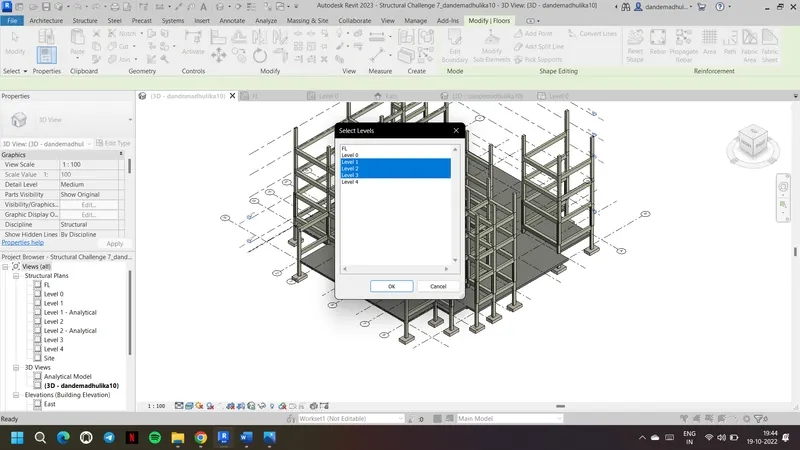
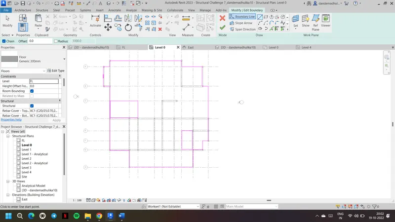
15. Use edit bpundary option and create openings in floor as shown wherever stairs and elevators are inserted
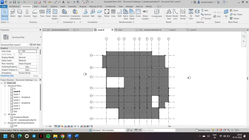
16. Copy the created floor and paste it in all levels using align to different levels option
17.Now choose the truss option and insert truss at roof level
18. Check the model in 3D to check th eopenings of floors, beams, columns and foundation
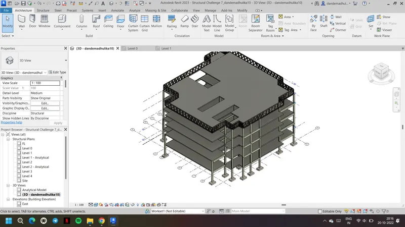
Result: Components like foundation, beams, columns, roof trusses, floors, floor openings if any for elevators and stairs are included in the structural model
4) Using the architectural model, include the following components based on the type of structure selected
a. Wall Layout with appropriate material and finishing
b. Exterior façade with fancy finish
c. Interior partition walls to size rooms
d. Components to add details to a room ( Desk, Chair, Lighting, Plumbing fixtures)
e. Add components such as stairs Elevators
f. Have at-least one side of the building with curtain walls and glass panels
g. Include interior and exterior lighting fixtures
h. Place proper topographic components from outside ( Trees, Parking, Plants) to add details to the model
Aim & Introduction: To include components like exterior, interior walls, components in rooms, partition walls, stairs, elevators, lighting fixures etc in the architectural model
Procedure:
1. Open the architecture template in revit model
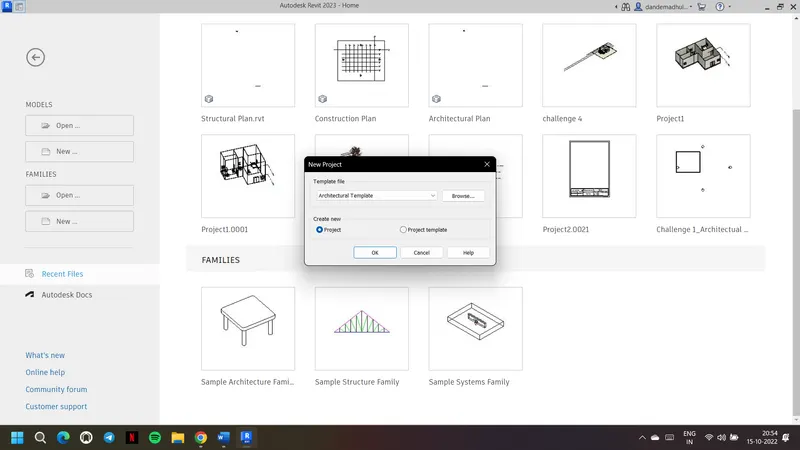
2. Save it as architecture model, collaborate it and save it as central model. Also synchronize it
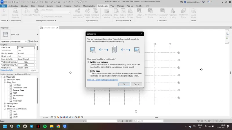
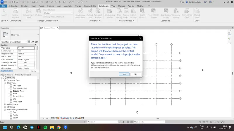
3. Create the grids in the model according to the plan with respective offsets
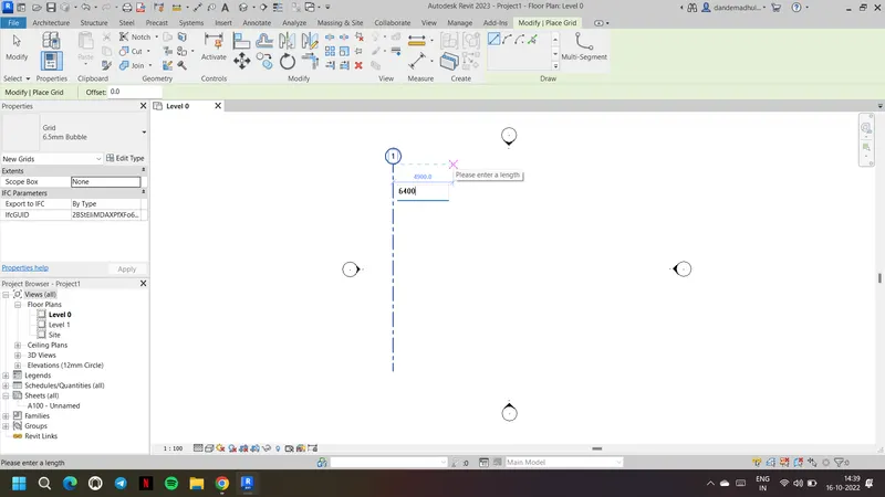
4. Choose grid option and create longitudinal and transverse grids as shown below
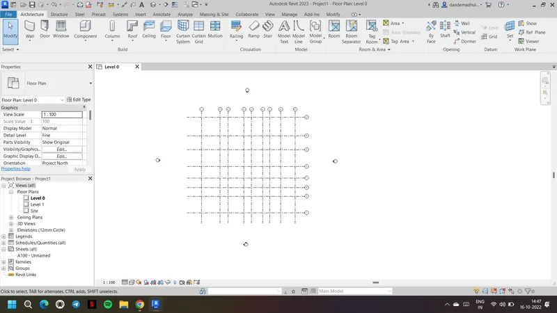
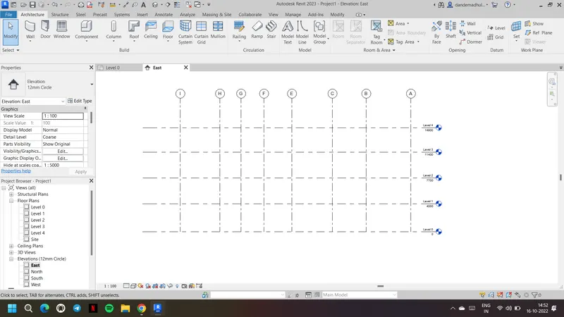
5. Now open the elevation view and create the levels
6. Create foundation level at -1.5m, first level at 4m, second, third and fourth levels at 3.7m and for roof provide 2.5m
7. Now open the ground level and choose wall from architecture toolbar
8. Choose exterior wall and edit it as required place it as per the plan
9. Choose interior walls and place them to provide partition and to form the rooms
10. Also edit and create another interior wall for partition choose them accordingly with respect to the rooms
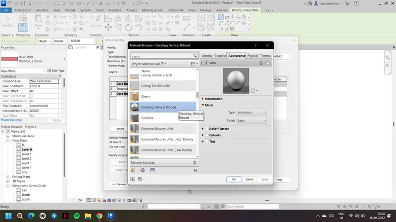
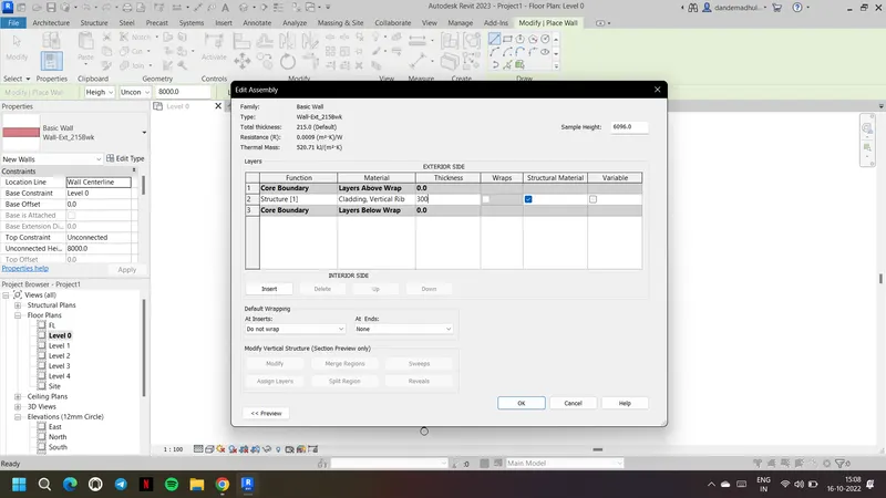
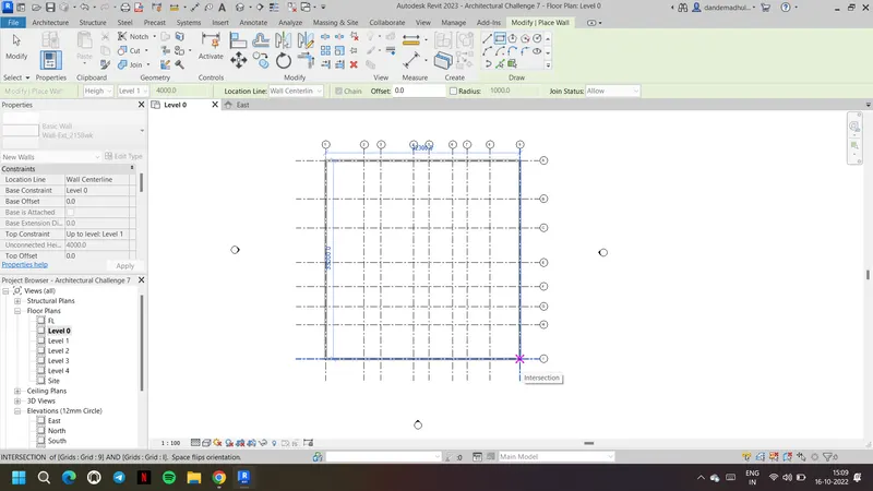
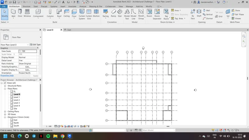
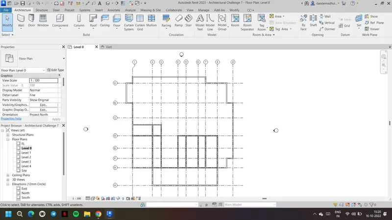
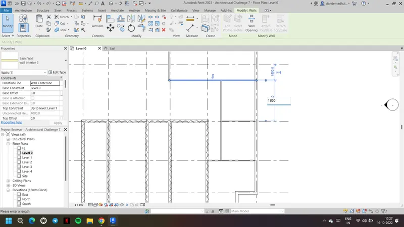
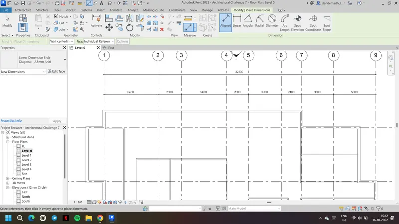
11. Now go to insert tab and form load family load all the basic components
12. Using place the component option, place tables, chairs, sofa, lighting accordingly in manager room, meeting rooms, break area, ideam room etc
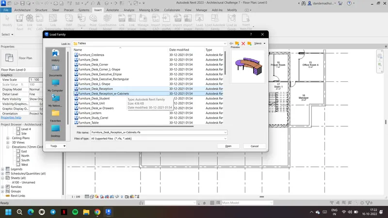
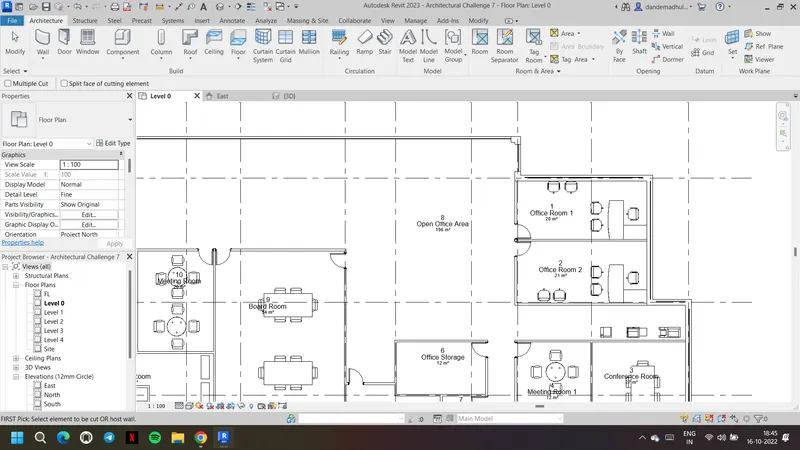
13. Choose stairs option and place them wherever required and using floor openeings connect them between the levels
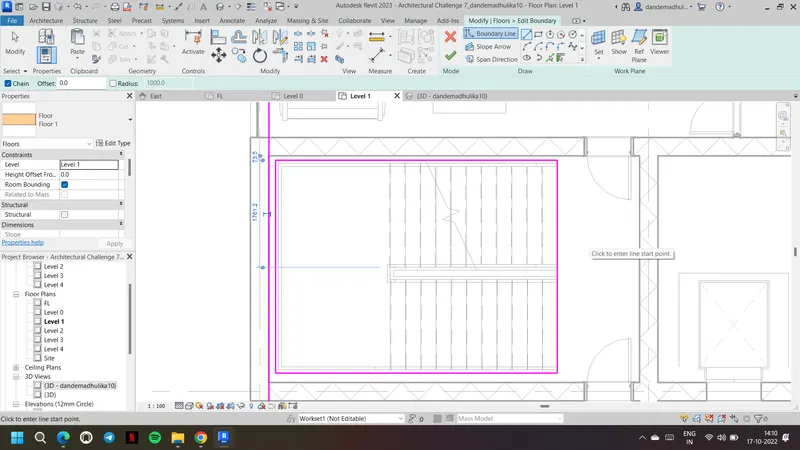
14. Also load the elevator form load family and place according to the plan
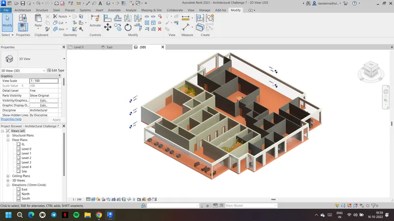
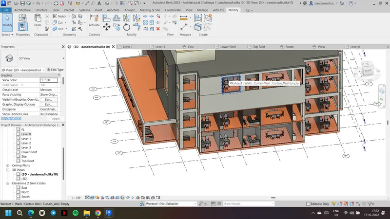
15. Create the outside floor/road and place a busstop and benches, dustbins as shown
16. Also place some planting, place the parking stands and parking areas for the vehicles
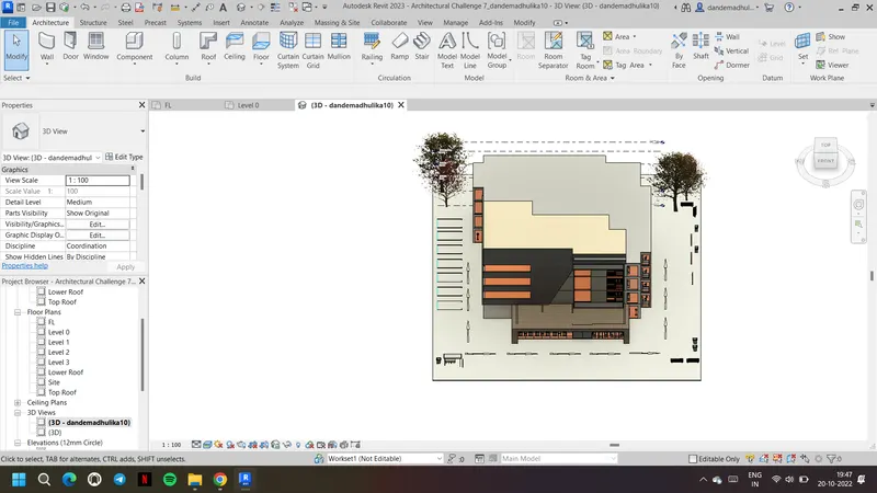
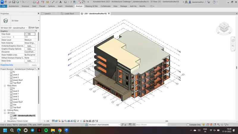
Result: Components like exterior, interior walls, components in rooms, partition walls, stairs, elevators, lighting fixures etc are included in the architectural model
5) Provide a set of drawings in an architectural and structural model to list the following details with categories and appropriate sheet templates included
a. Floor Plans with Annotations
b. Elevations
c. Sections
Aim & Introduction: To provide the sheet templates with set of drawings of architectural and structural model floor plans, elevations and sections
Procedure:
1. Open the revit and view toolbar. Select the sheets from it.
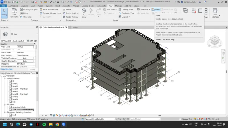
2. Select the titleblock as required, else load it from load family and choose the template
3. Change the annotations accordingly owner details, project name etc to be given and click apply
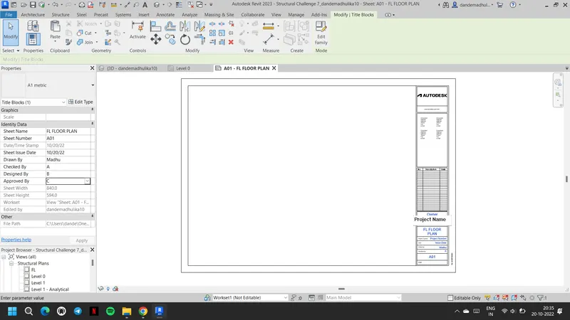
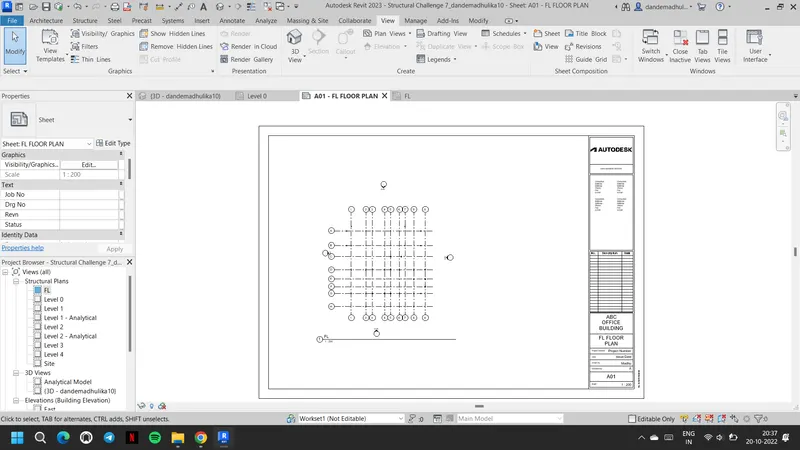
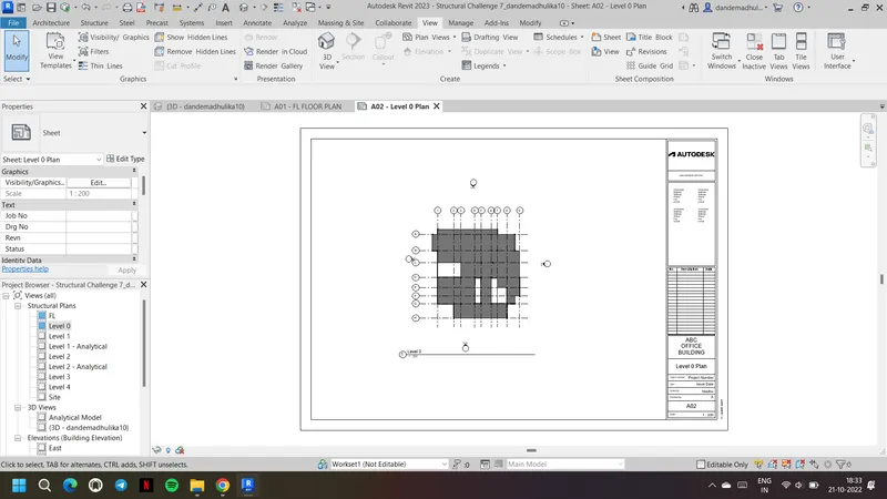
4. Now drag the required view and place it in the sheet. Foundation level floor plan is placed in the created sheet
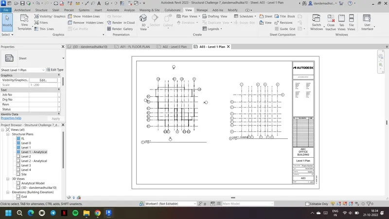
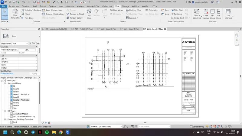
5. Similarly all other floor plans of architectural and structural model are placed in sheets
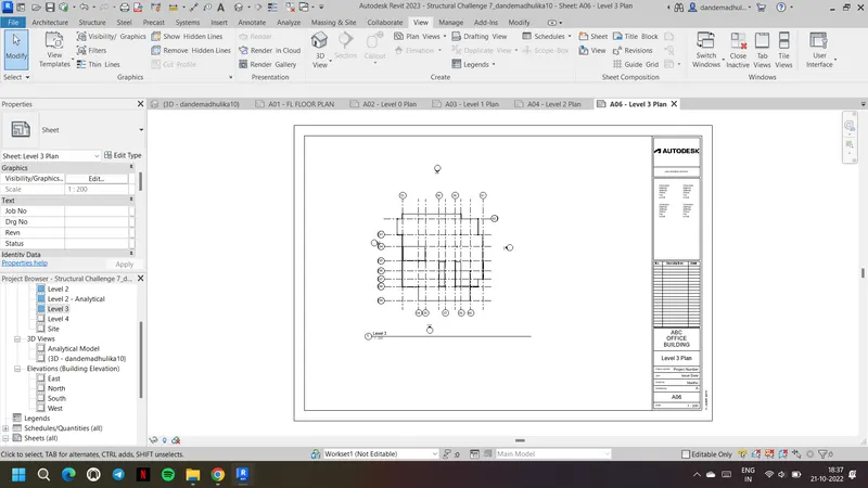
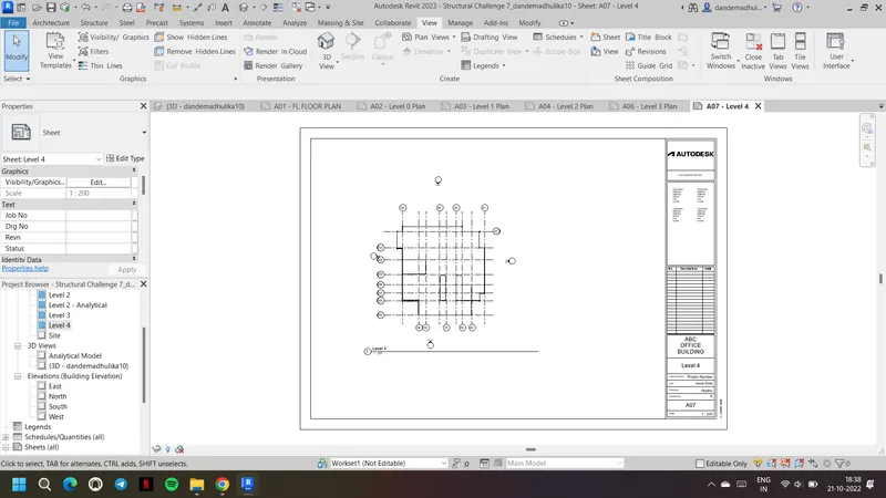
6. Now from view toolbar form east, south, west and north views and create sheet templates
7. Place the elevation views of both architectural and structural model in sheets
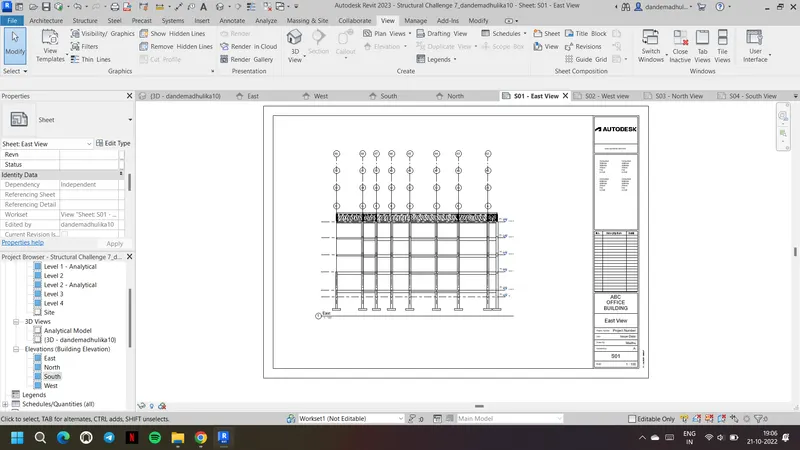
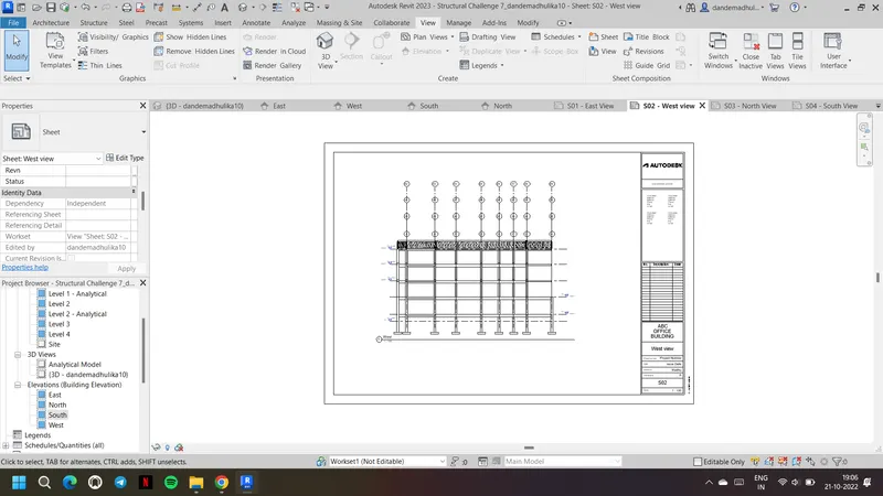
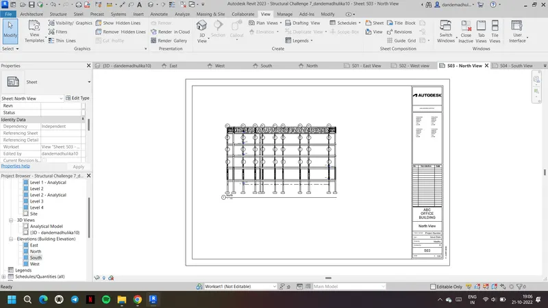
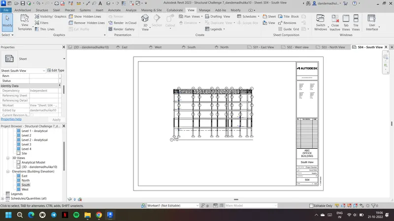
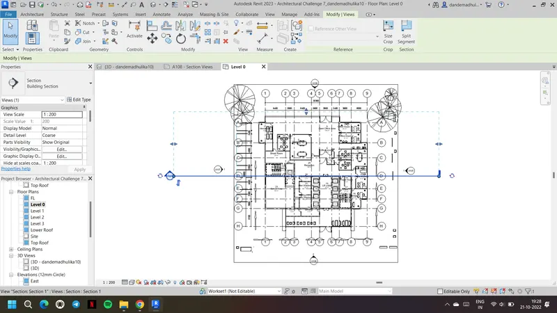
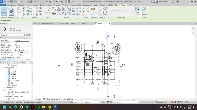
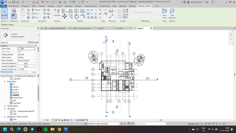
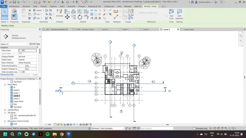
8. From view toolbar select section and draw the sections wherver the drawing is required in both models
9. Insert the section views in the sheet templates accordingly
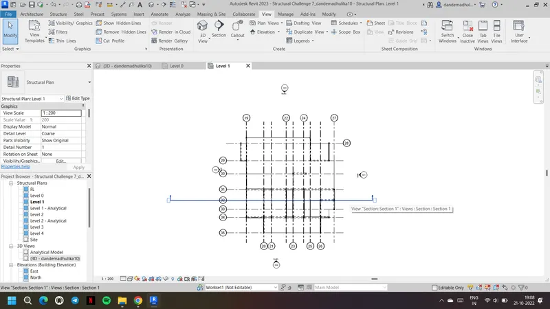
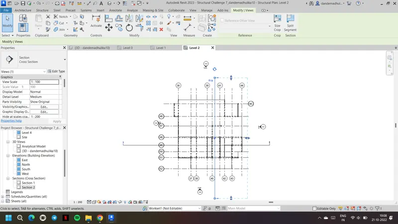
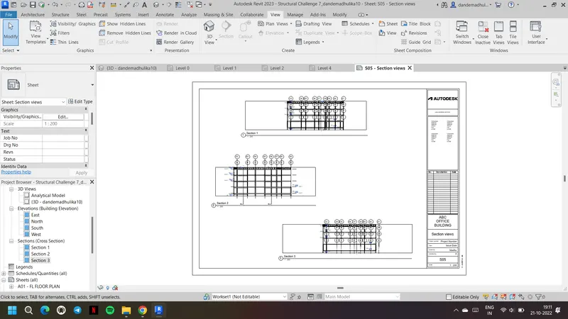
10. The following are for the architectural model
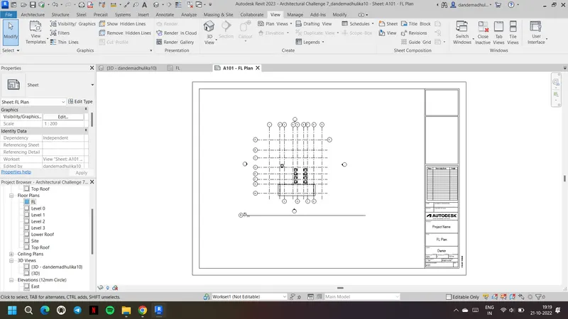
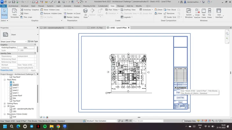
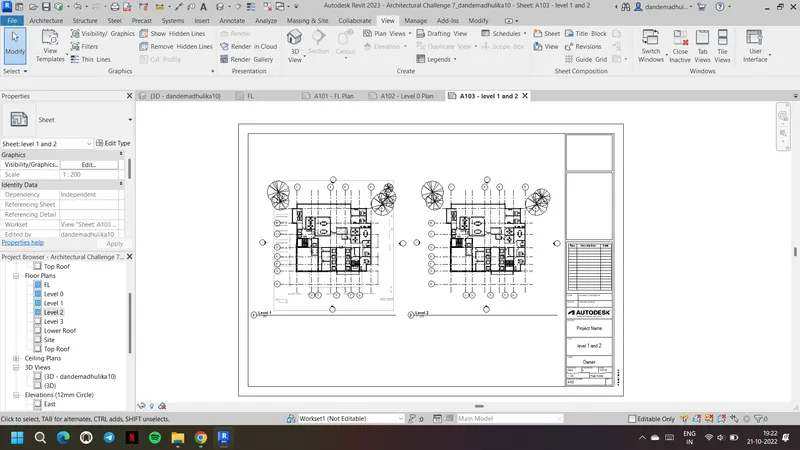
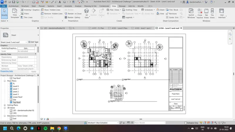
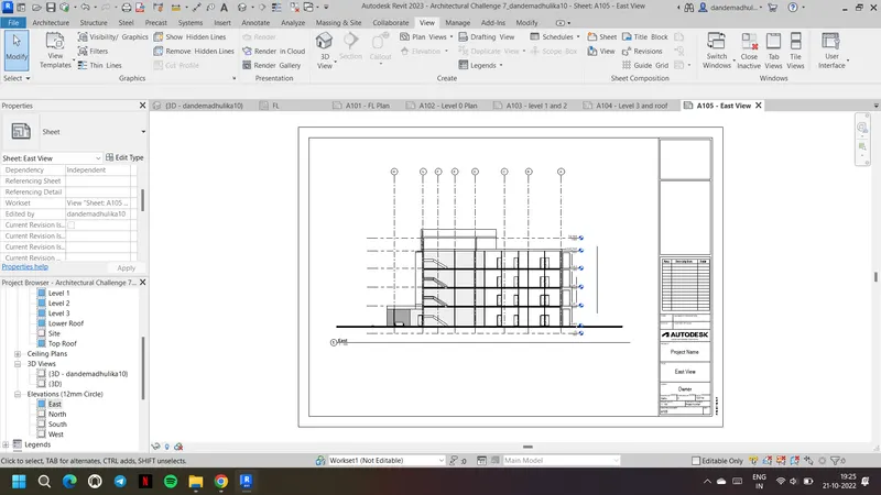
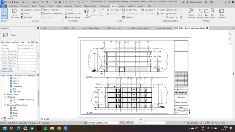
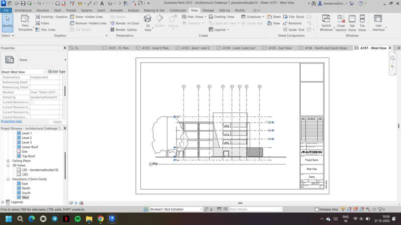
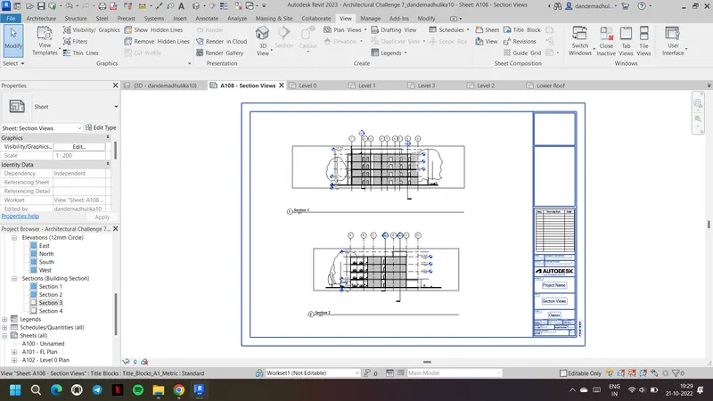
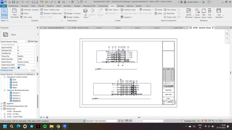
Result: The sheet templates are provided with set of drawings of architectural and structural model floor plans, elevations and sections
6) Using the Rendering settings, Render images of the 3D model produced and include the rendered images to the drawing sheets
a. Rendering from interior rooms
b. Rendering from out showing topographic features
c. Rendering through structural framing
Aim & Introduction: To provide the rendering images of the 3D model produced and to insert them in the drawing sheets
Procedure:
1. Open the revit and view toolbar. Select the sheets from it.
2. Select the titleblock as required, else load it from load family and choose the template
3. Change the annotations accordingly owner details, project name etc to be given and click apply
4. Give RR command and choose the settings of rendering and click on render
5. The rendering image of the selected view is formed accordingly
6. To get render view of particular room or view.
7. Go to view toolbar select camera and give camera in floor plan wherever view is required.
8. Create rendering images of interior rooms, out view and strutural framing
9. Insert these rendered images in the sheets
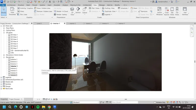
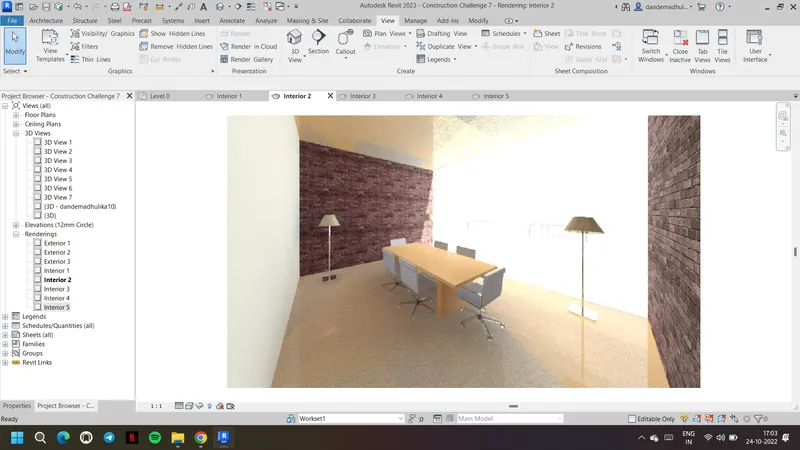
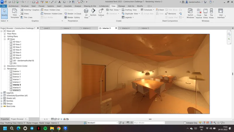
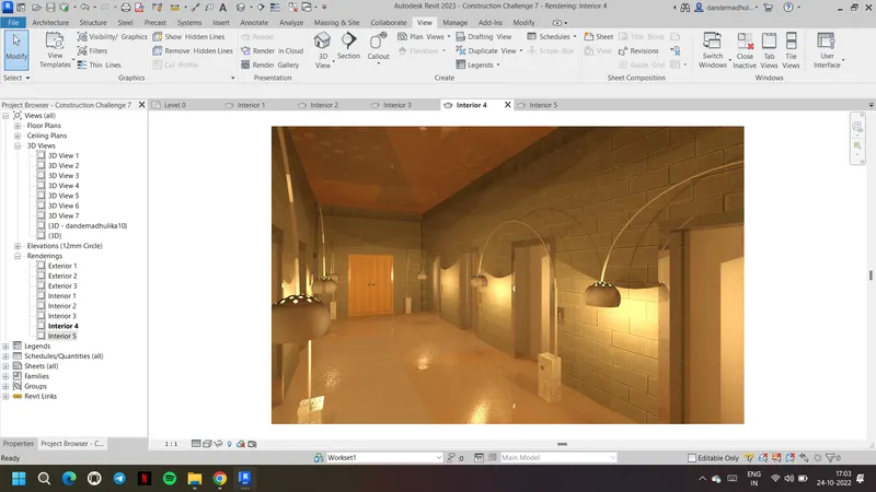
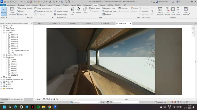
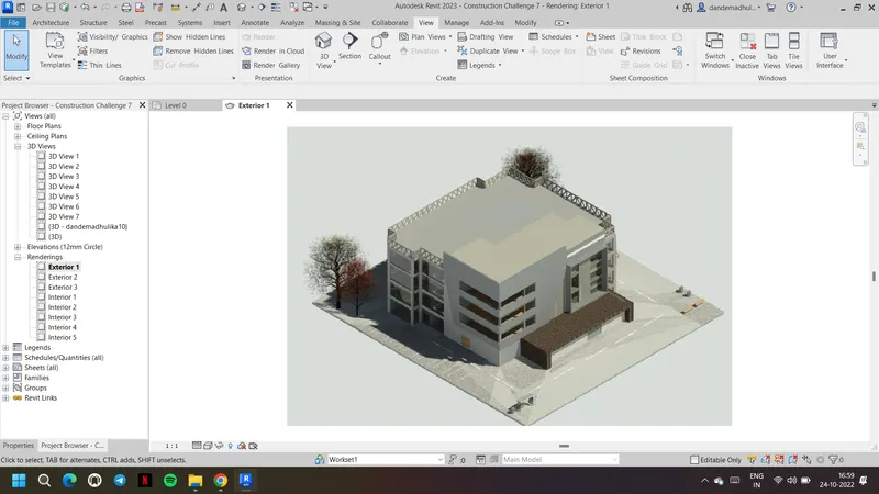
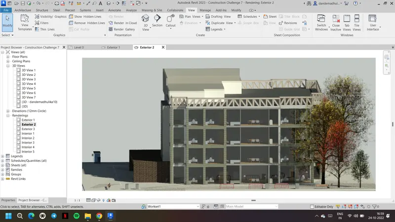
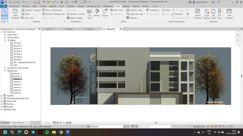
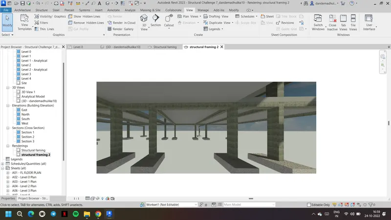
Result: The rendering images of the 3D model are produced and inserted them in the drawing sheets
7) Print the set of drawing sheets created and submit the drawings from the architecture and structure model
Have printed the set of drawings created from architectural and structure model and attached the drawing sheets in the challenge