Creating a Residence Layout, Seating plan, Toilet and Utility room plan using AutoCad
Aim & Introduction: To create a Residence Layout, Seating plan, Toilet and Utility room plan using AutoCad. Demonstration of how residence layout, seating plam, toilet and ulitity room is drawn using AutoCad. More about layers, blocks and arrays are discussed.
1. Creation of a given residence layout using AutoCad.
Procedure:
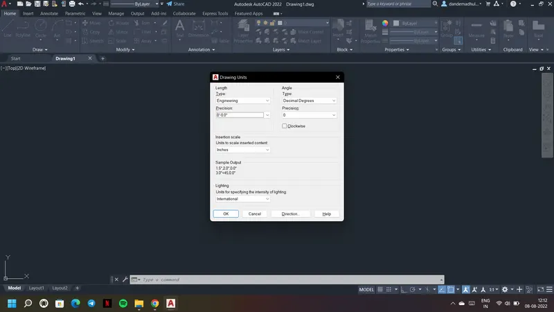
1. Open new drawing choose imperial system and go to units choose Engineering units.
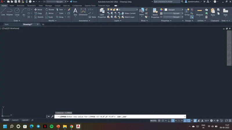
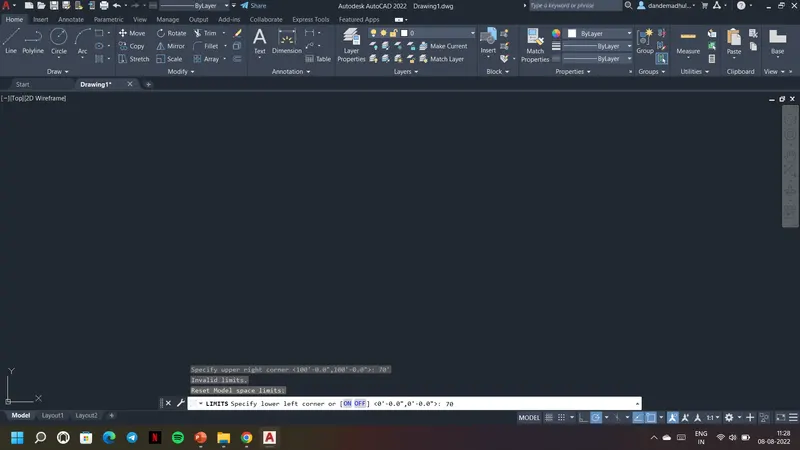
2. Go to Limmax command and limits command to give maximum and minimum boundaries for the Auto Cad sheet.
3. Give Zoom cammand and select all.
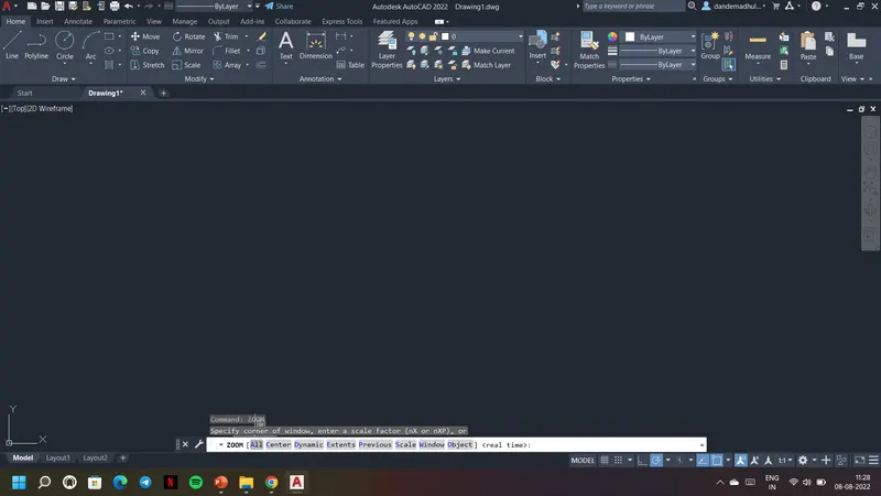
4. Give coomand Xline and draw horizontal and vertical line as shown below.
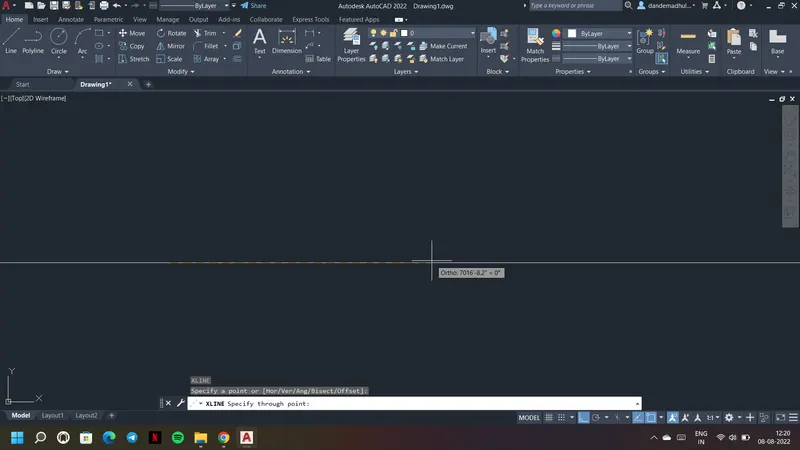
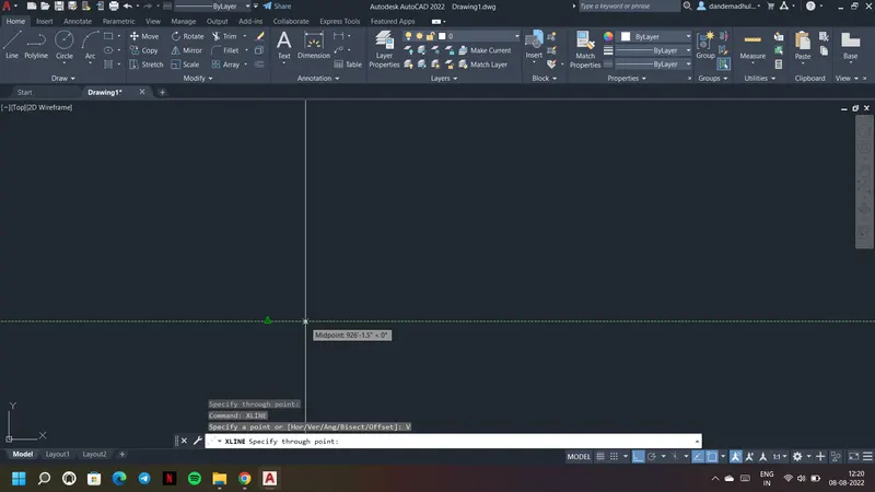
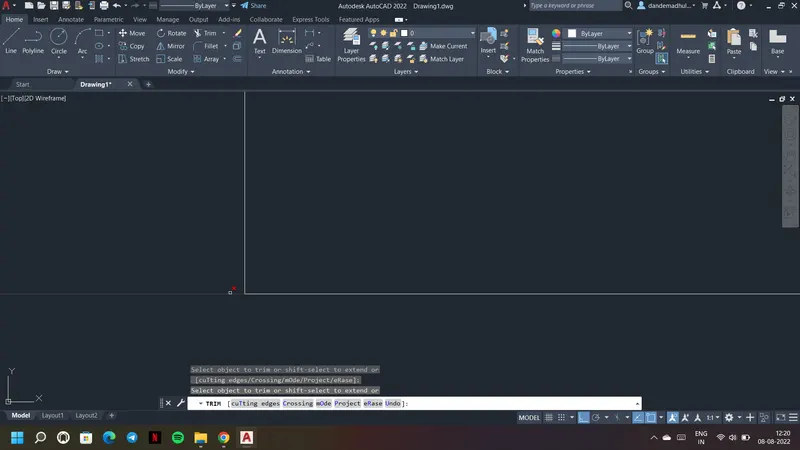
5. Choose Trim command and trim the extra parts to form vertex of the plan/building.
6. Choose line command and according to the plan mark 12'6" line in x-direction and 43'6.5" in y-direction
7. Trim the extra parts using trim command
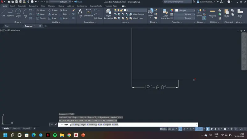
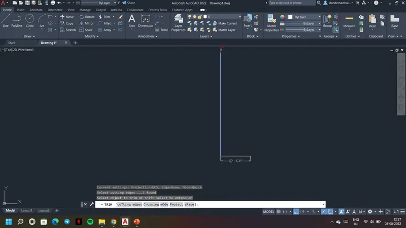
8. Use Dimstyle command to set the dimension style, units and pattern accordingly
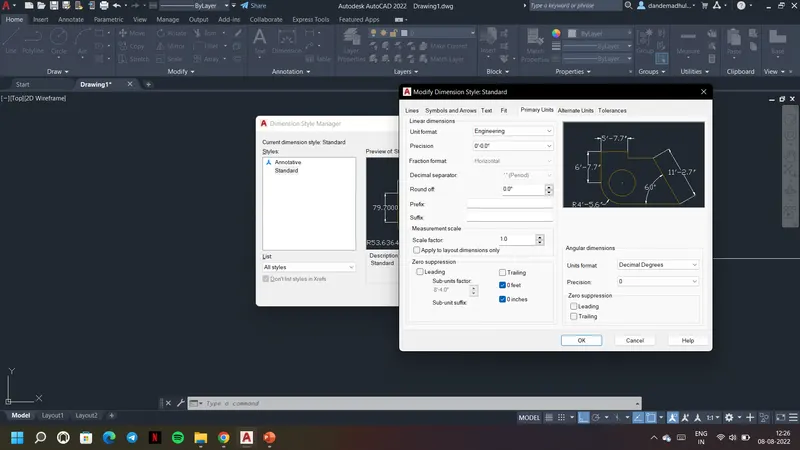
9. Edge of the given residence is formed
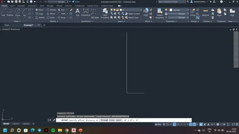
10. Use Offset command to draw the wall thickness. Give offset distance as 9" and direction of offset and enter.
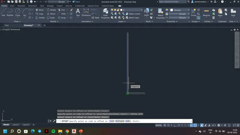
11. Trim the extra parts to form a perfect wall
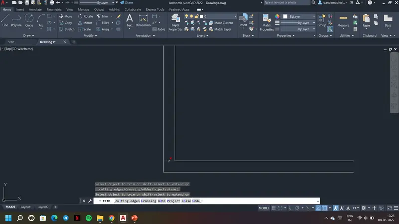
12. Now use the line command, ortho mode and distance mentioned in the plan and draw kitchen
13. Use offset distance as 4.5" as it is the interior wall
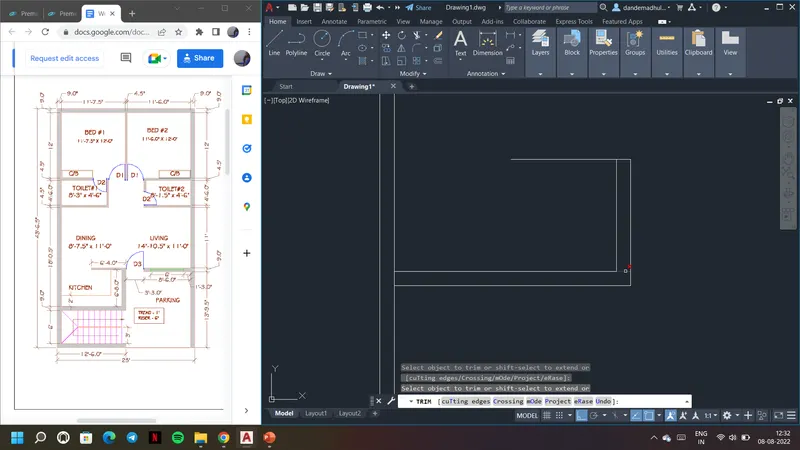
14. Now use the line command, ortho mode and distance mentioned in the plan and draw toilet
13. Use offset distance as 4.5" as it is the interior wall
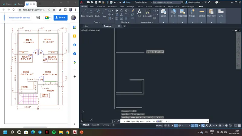
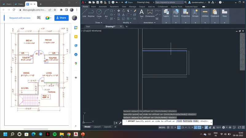
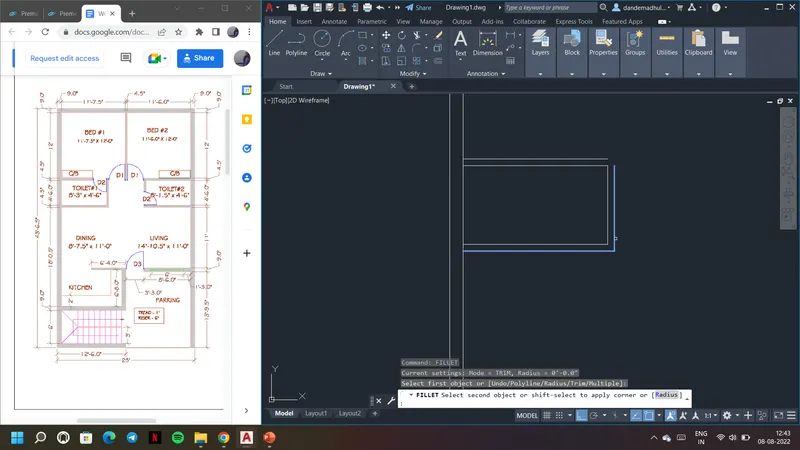
14. Use fillet option to join the ends and also leave the gap for the door as per the size of the door mentioned
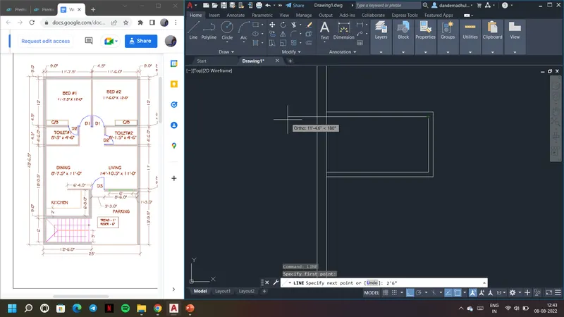
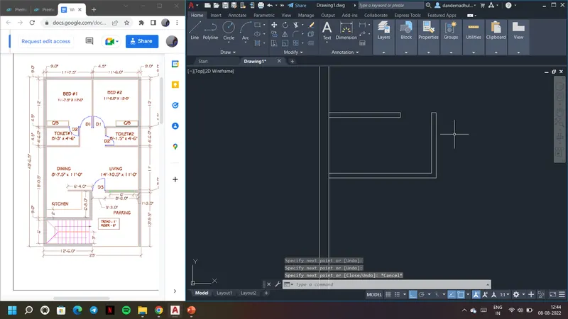
15. Now finish the outer wall. use the dimensions mentioned and draw the bed rooms
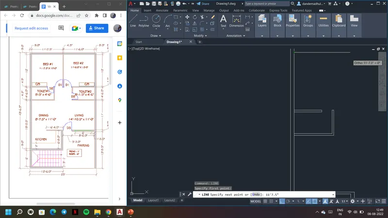
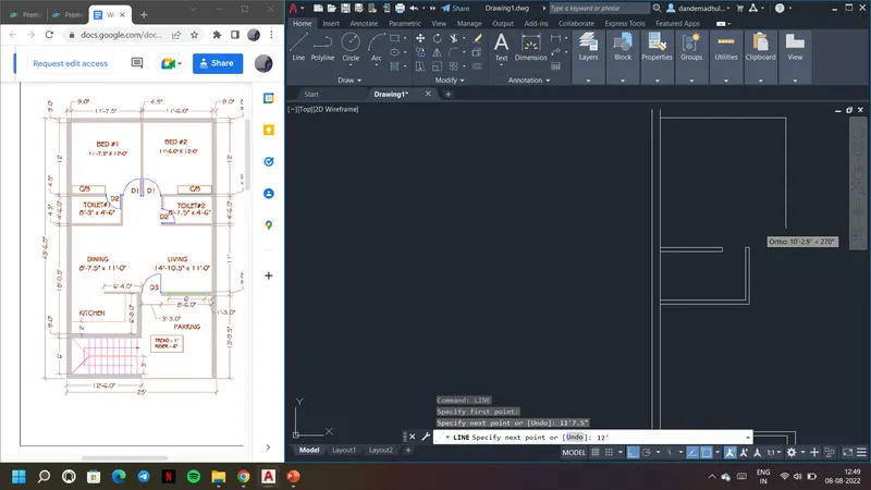
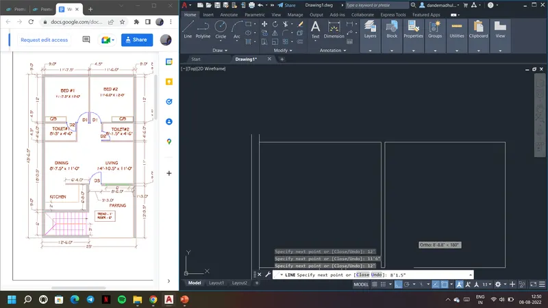
16. Use offset command. Offset distance as 9" and direction outside.
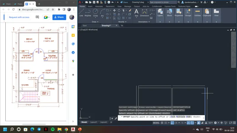
17. Use fillet option to join the ends of the walls
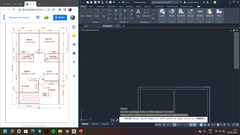
18. Similarly draw the right portion of the plan. Draw the toilet with given dimensions
19. Offset distance is taken as 4.5" as it is interior wall
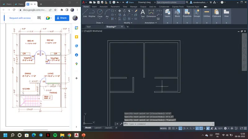
20. Leave the gap 2'6" for door as mentioned and draw the wall
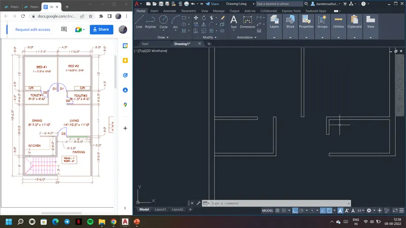
21. Exrend the drawing to living room and offset it to 4.5"
22. Offset distance for interior walls is 4.5" and for exterior wall is 9"
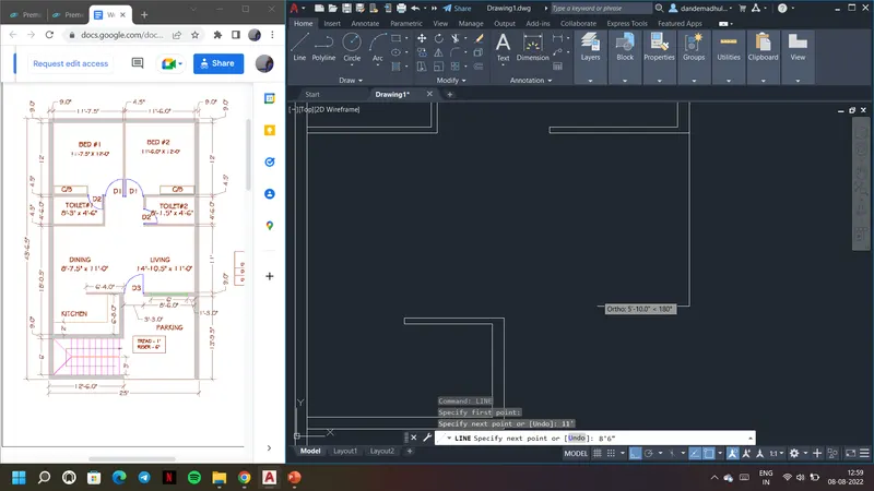
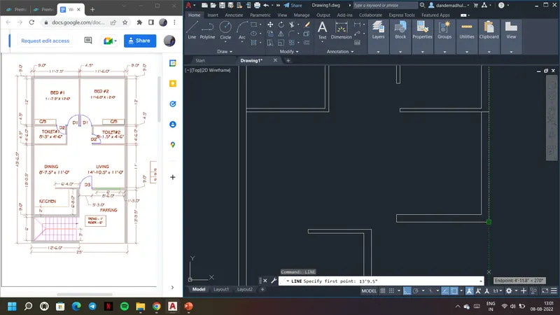
23. Draw line with 13'9.5" in 270 degree angle direction as shown
24. Use offset 9" and finish the exterior wall of the plan
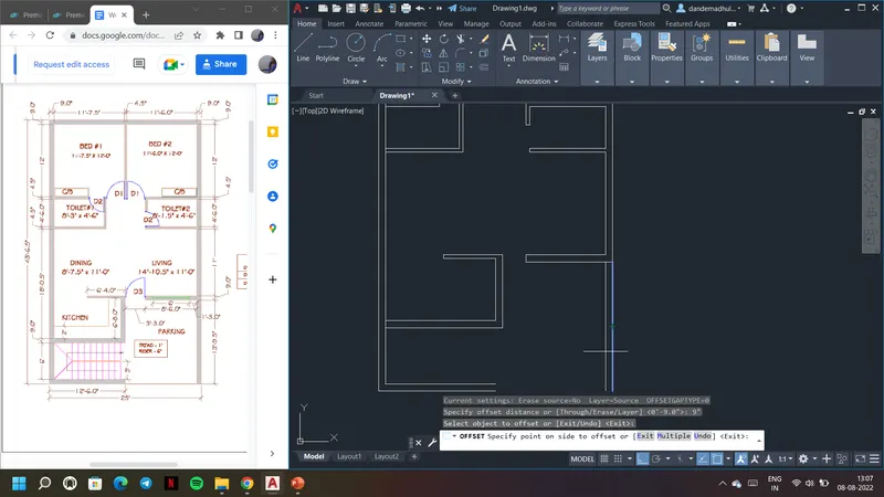
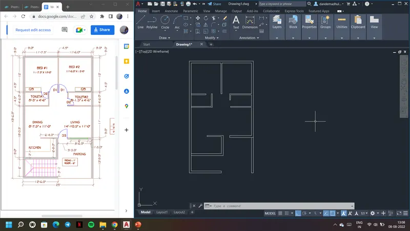
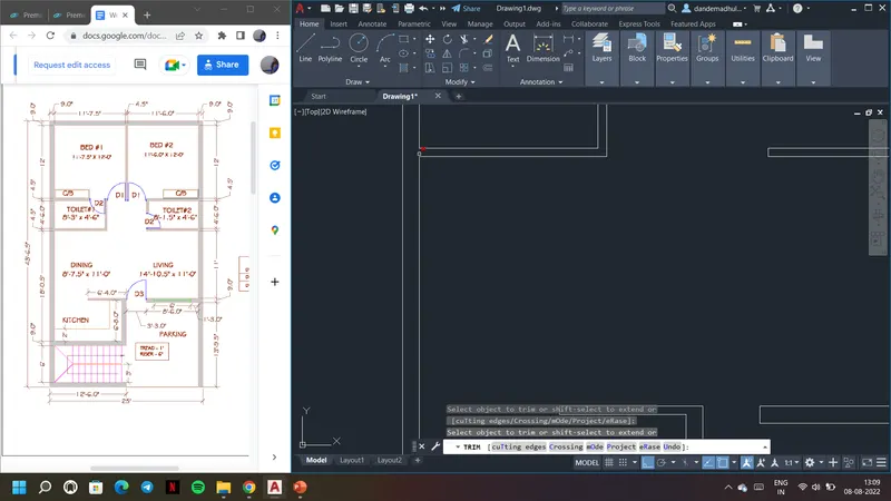
25. Remove the extra parts using Trim command to form the outer layer of the plan
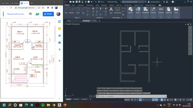
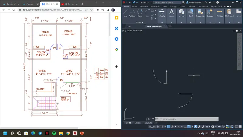
26. Now use blocks to draw doors
27. Draw a rectangle woth 1.5X3 dimensions and copy this rectangle and place it at 3' distance as width of the door 1 is given as 3'.
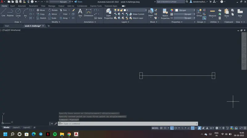
28. Drawthe hinge with0.1 units and line with panel thickness 0.15 units.
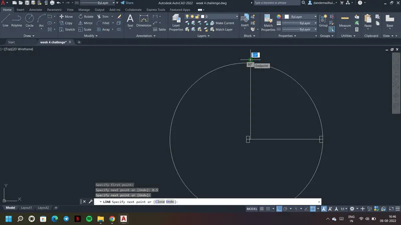
29. Now draw a circle with hinge edge as center and 3' distance rectangle as second point.
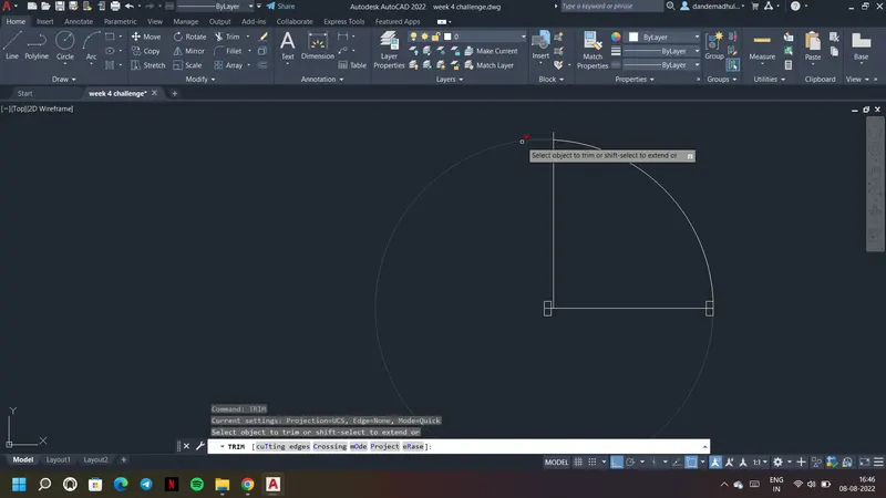
30. Trim the remaining part of circle to get door block
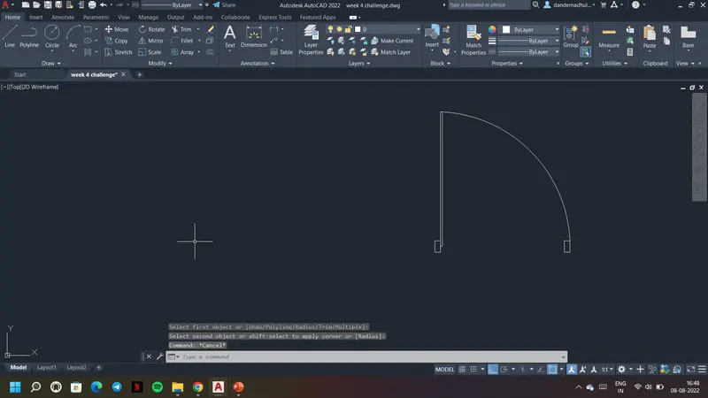
31. Give block command and select the door and pick point
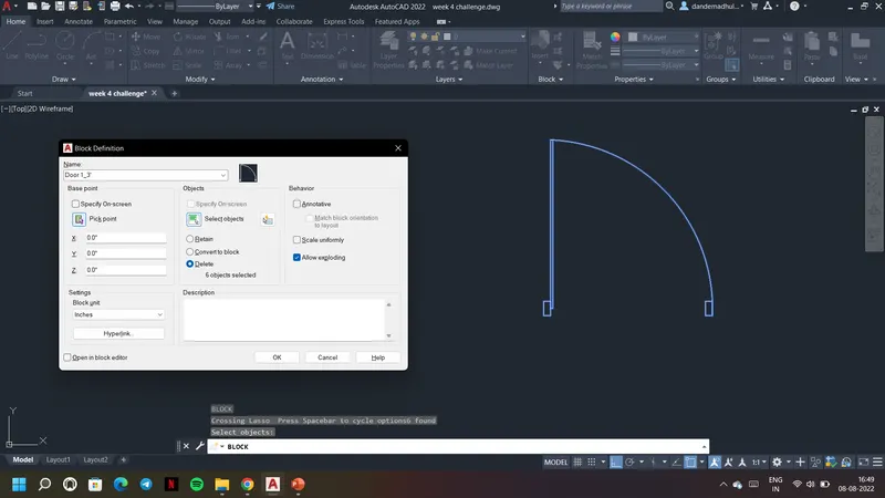
32. Similarly draw other two doors with 2'6" and 3'3" as door width.
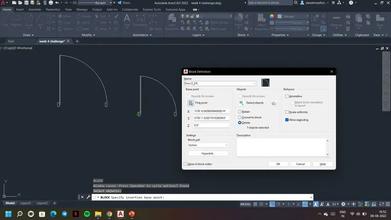
33. If block was drawn incorrectly then go to block edit definition and edit the block as shown
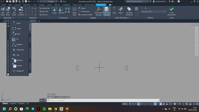
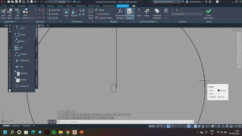
33. Save the changes and block get updated
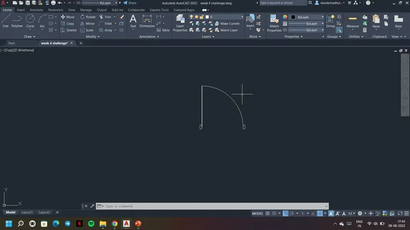
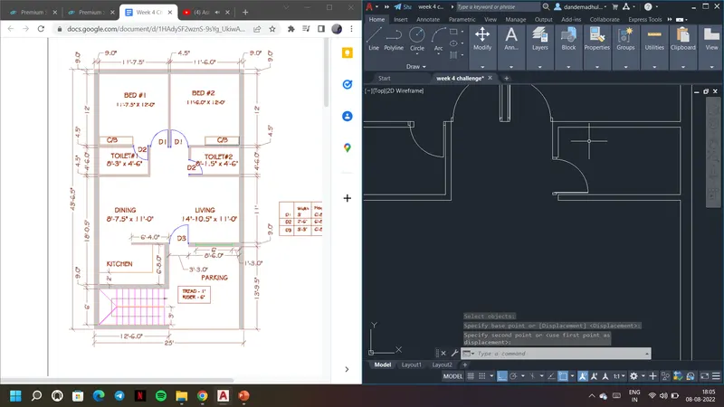
34. Use insert option and insert the blocks. There will be rotation option and scale option while inserting the block.
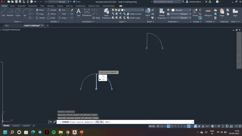
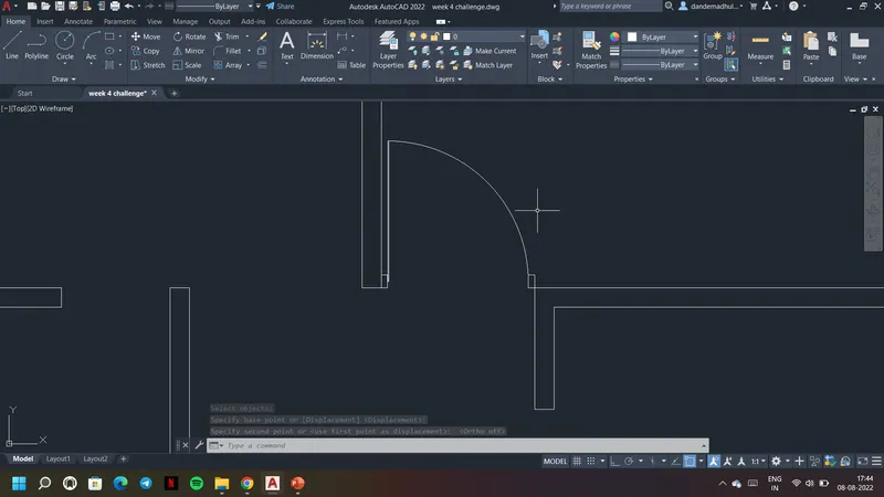
34. Insert doors repectively as given in figure
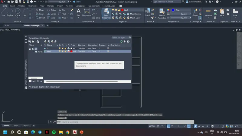
35. Now use layer command and assign layers to the draw walls and doors.
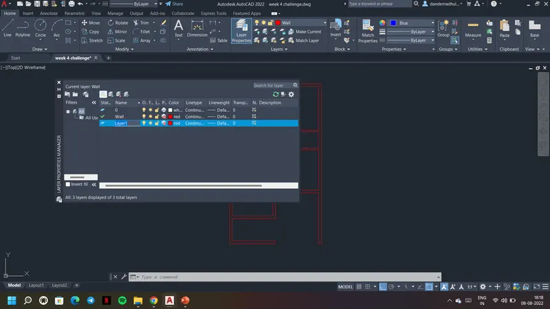
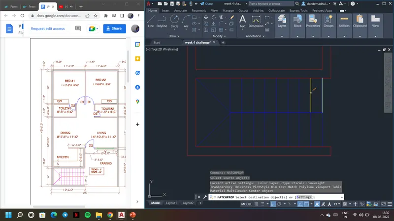
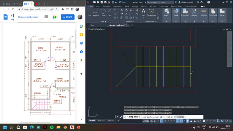
36. Use matchproperty command and match th elayer property for other doors
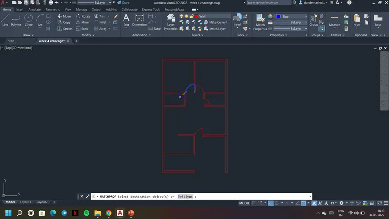
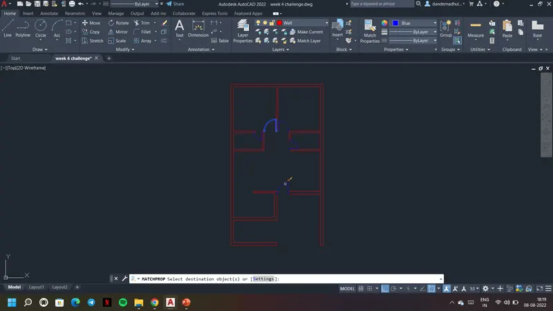
37. Draw 3' inch perpendicular line as shown to draw stairs. Use offset commanf and draw other rises with offset distance as 1'.
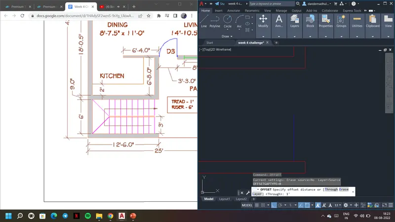
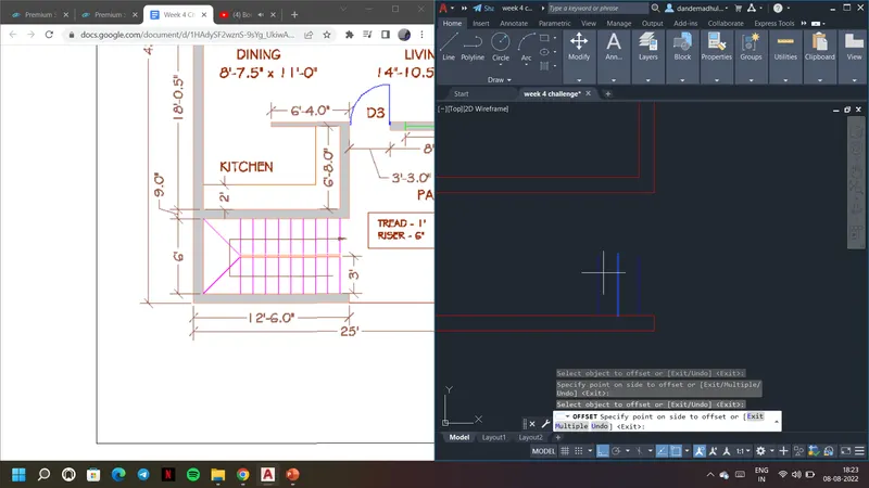
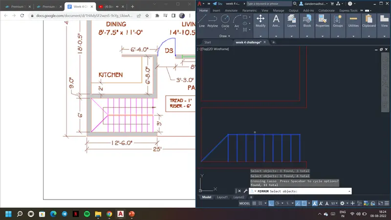
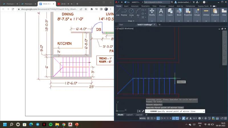
38. Draw th e inclined line as shown and use mirror comamnd to finish up the other side of stairs.
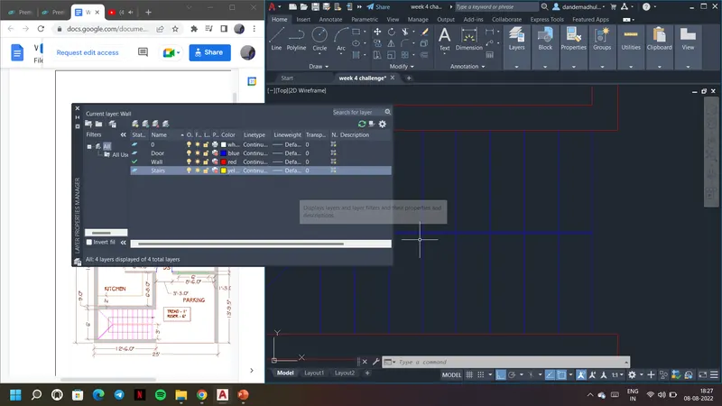
39. Create a stair layer and use match property as shown
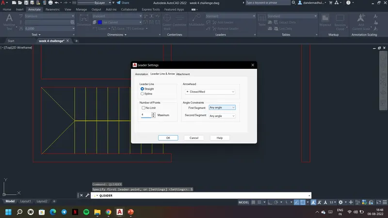
40. Use leader command and give number of points as four to set dimension leader as below
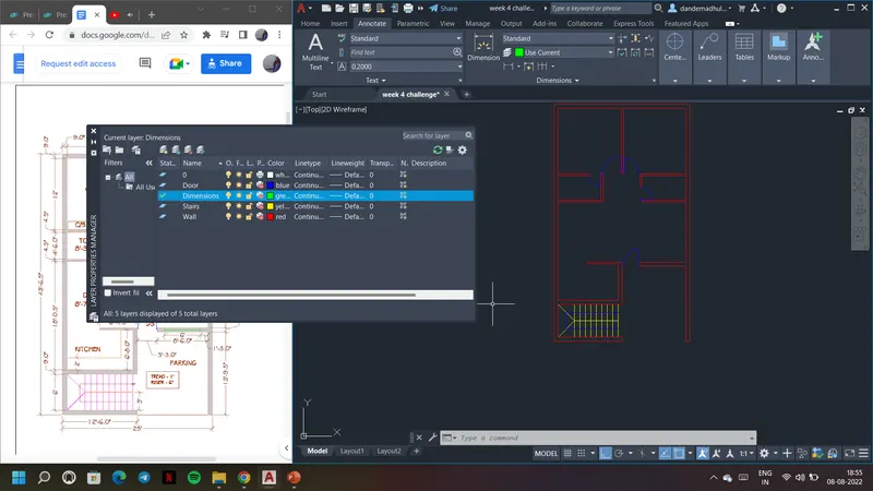
41. Create layers for dimensions and dimension text
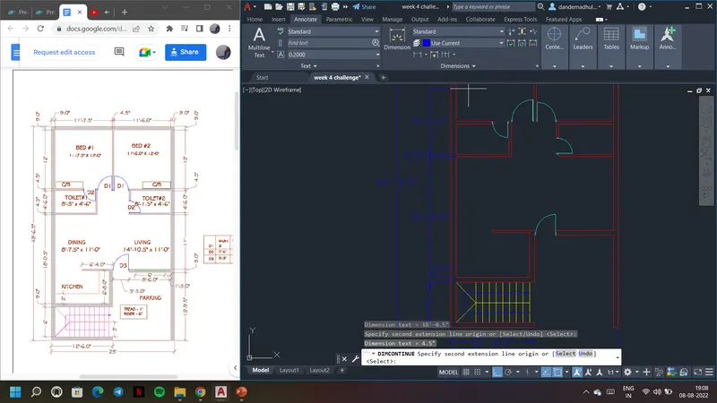
42. Give command dimlinear and dimcontinue to measure the dimensions
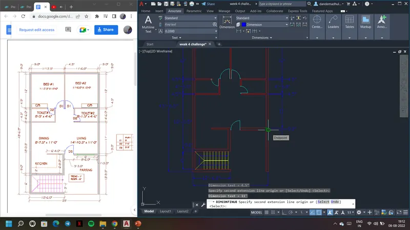
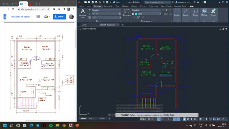
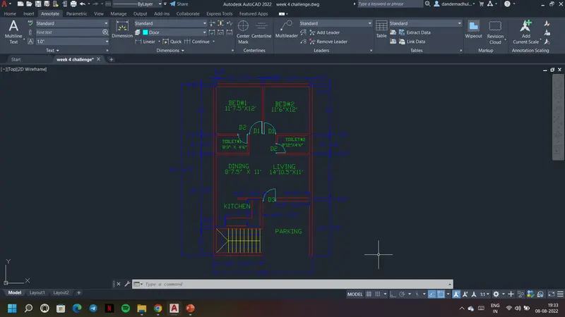
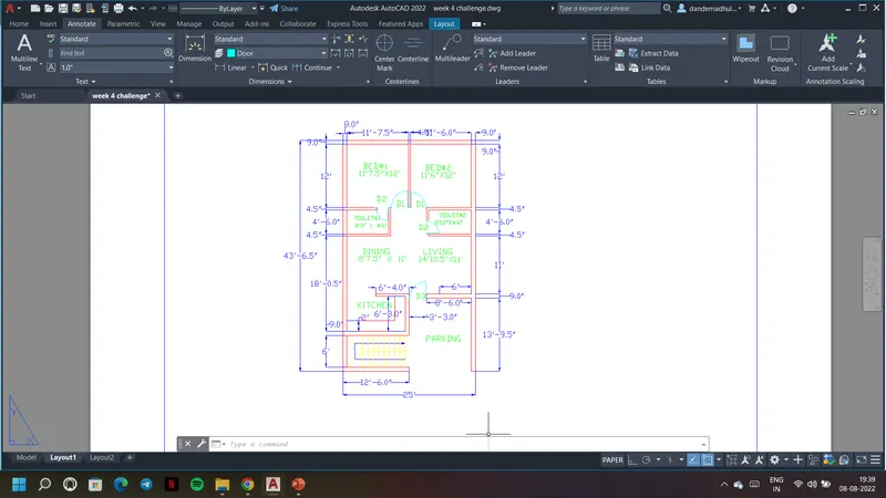
Result:
Layout of a residence plan
2. The seating plan for an outdoor canopy
Procedure:
1. Open new drawing choose imperial system and go to units choose Decimal Units.
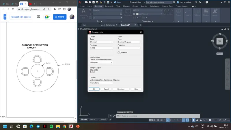
2. Go to Limmax command and limits command to give maximum and minimum boundaries for the Auto Cad sheet.
3. Give Zoom cammand and select all.
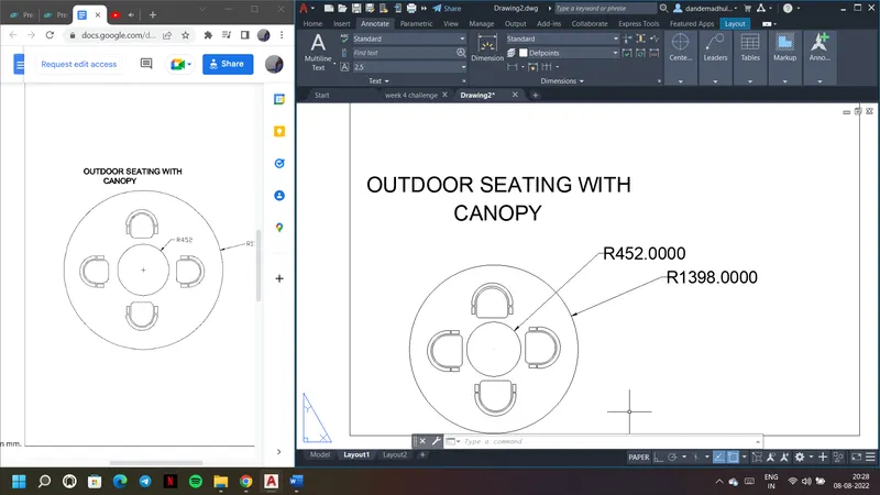
4. Give circle command and draw concentric circles with radius 452 and 1398 mm.
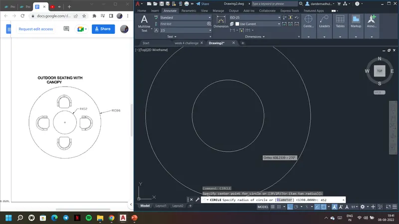
5. Draw a rectangle using rectangle command as shown.
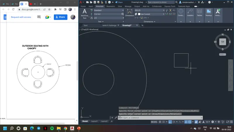
6. Draw arc at top of rectangle to form the chair and use fillet command to form a curve at ends as shown, give radius as 50 units
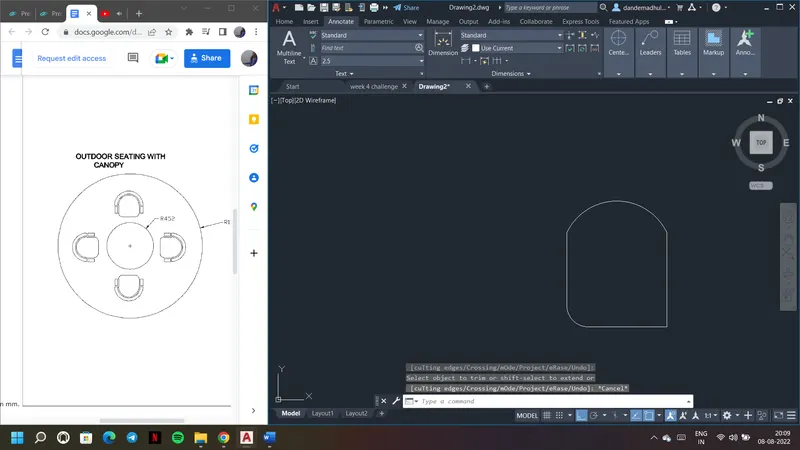
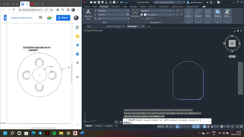
7. Draw rectangle at side as shown with rectangle comamnd for hand rest and use mirrror command.
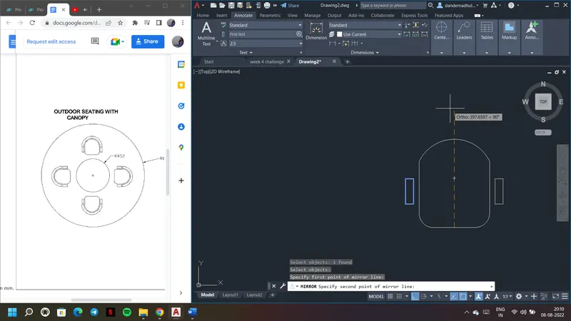
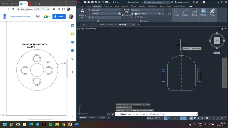
8. Give arc comamnd to form the top of the chair and use trim comamnd to trim extra parts.
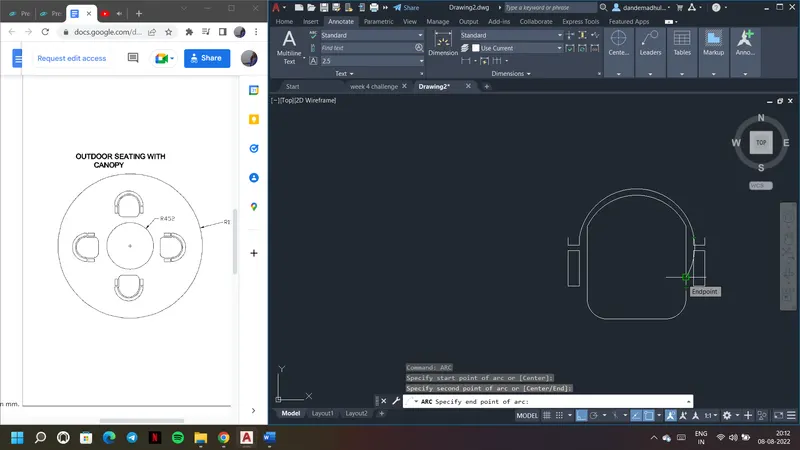
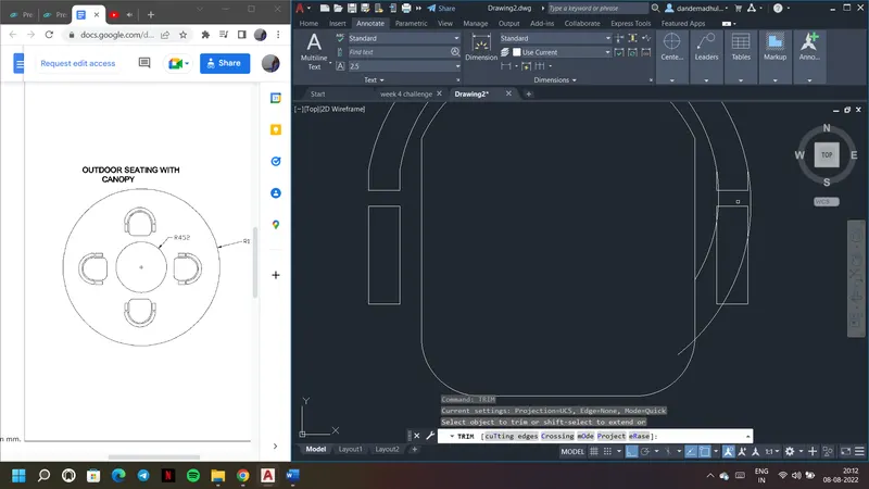
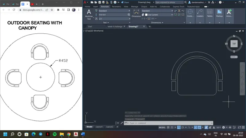
9. Go to block command. Select the chair object and a pick point.
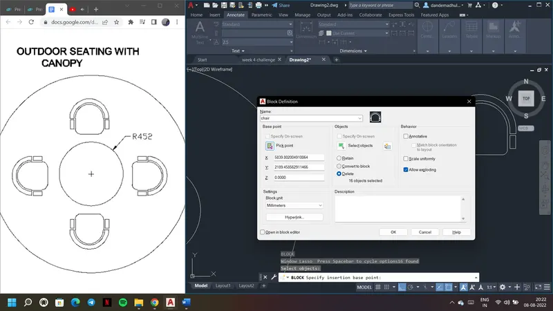
10. Use insert command and insert the block
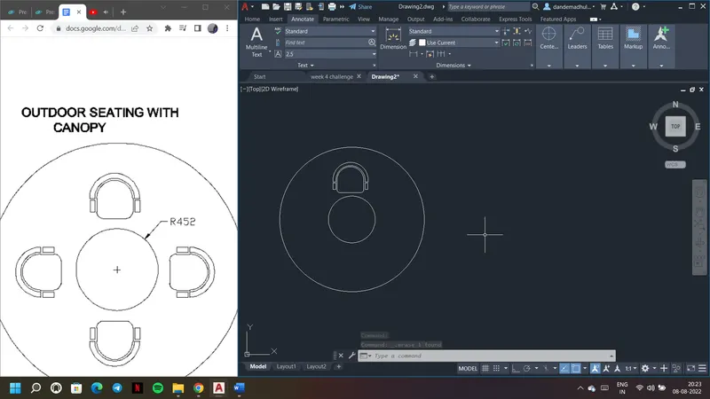
11. Use array command and polar array. Give number of items as four.
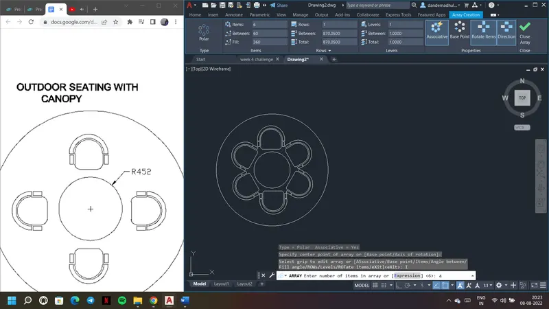
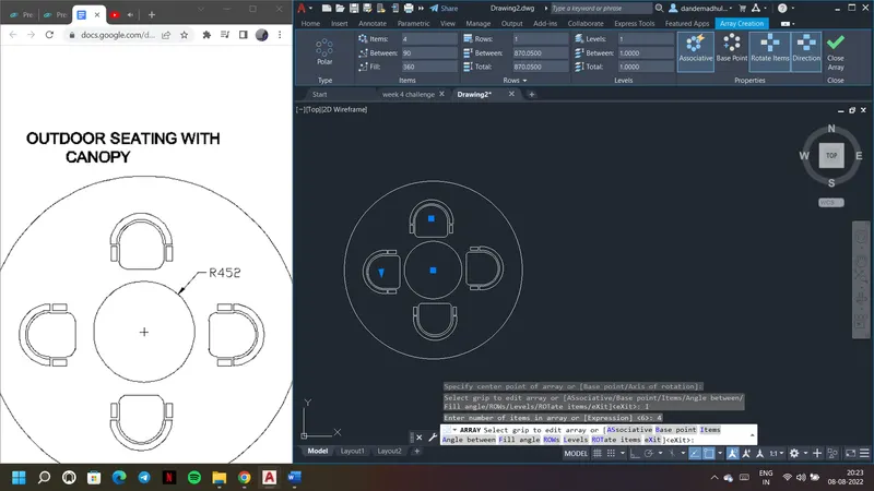
12. Use text comamnd and dimradius command to measure radius.
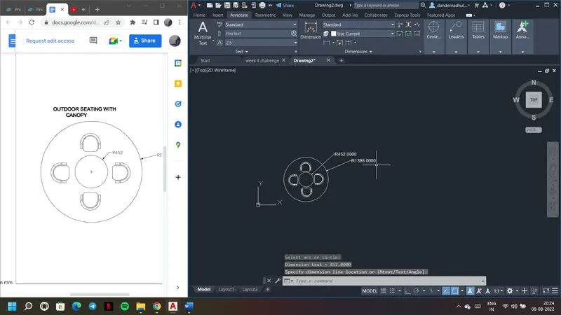
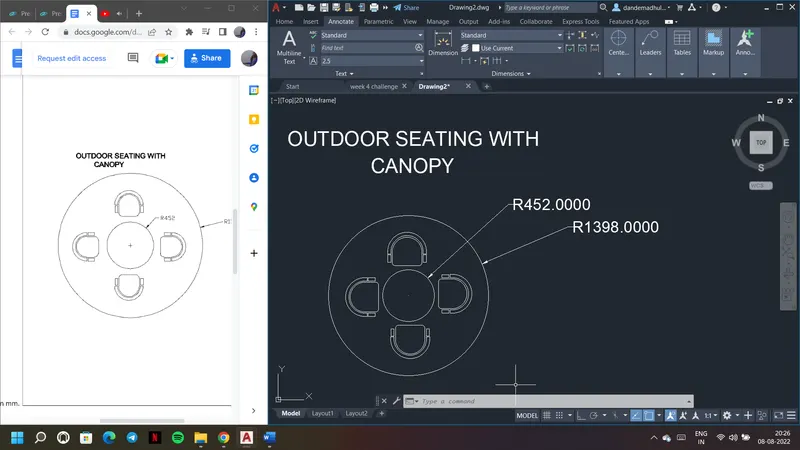
Result:
The seating plan for an outdoor canopy
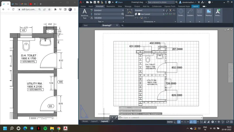
3. Part plan for the toilers and utilities room.
Procedure:
1. Open new drawing choose imperial system and go to units choose Decimal Units.
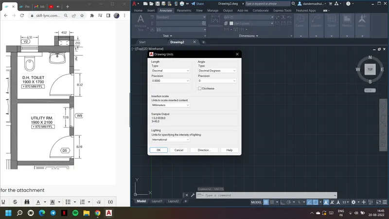
2. Go to Limmax command and limits command to give maximum and minimum boundaries for the Auto Cad sheet.
3. Give Zoom cammand and select all.
4. Draw utility room using line comamnd and ortho mode
5. Use offset comamnd and draw exterior wall with 300mm thickness and inner wall with 150mm thickness.
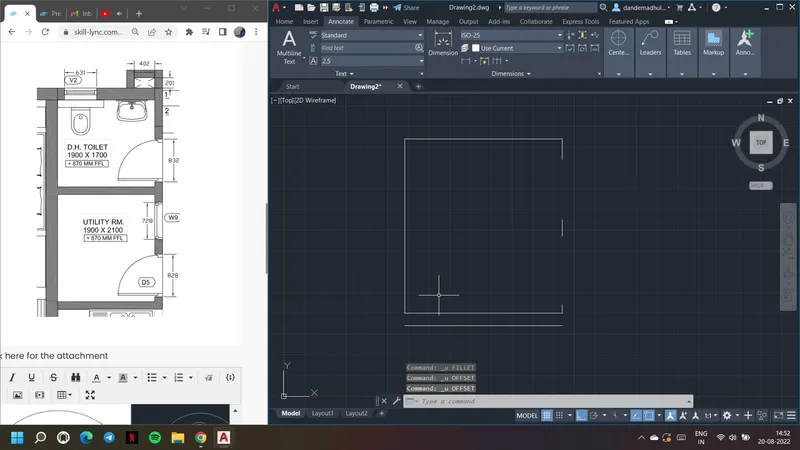
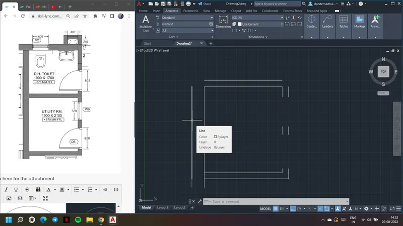
6. Draw toilet using the given dimensions using line command and ortho mode.
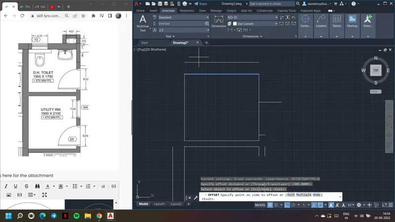
7. Draw the extra part with dimension 402 and 201 as given.
8. Use fillet command to join all the ends
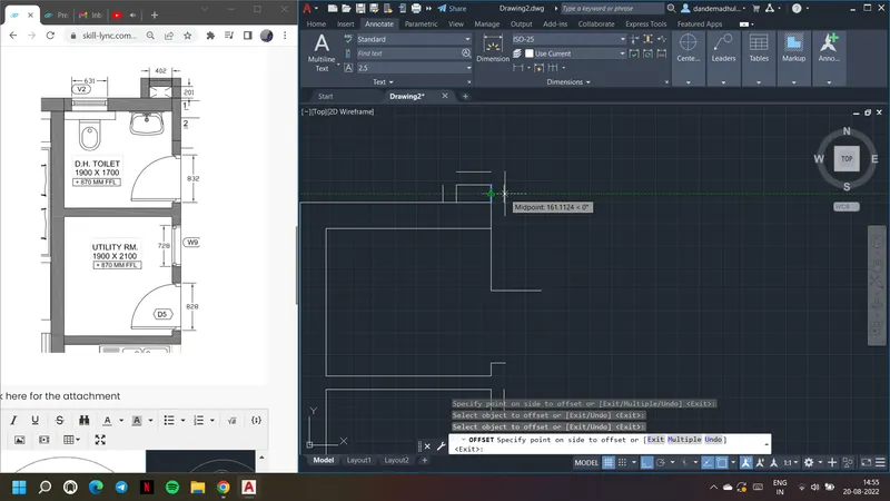
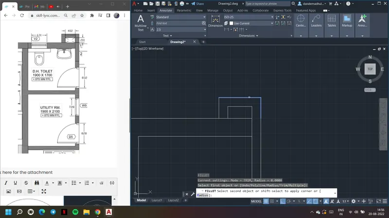
9. Draw window for utility room and toilet as shown below
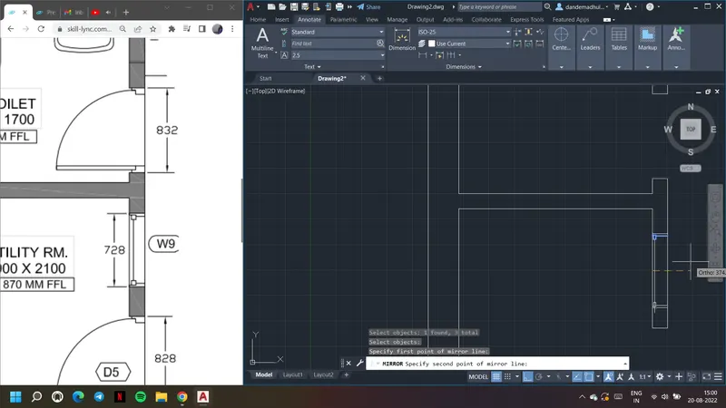
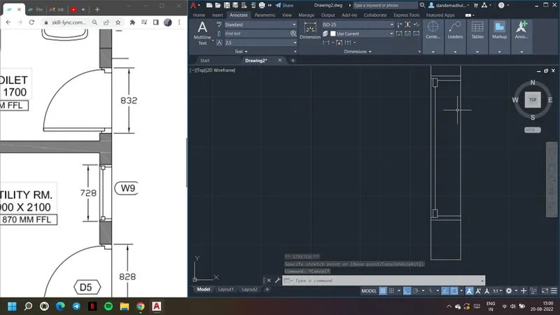
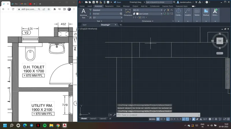
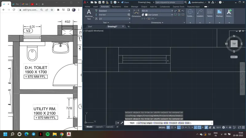
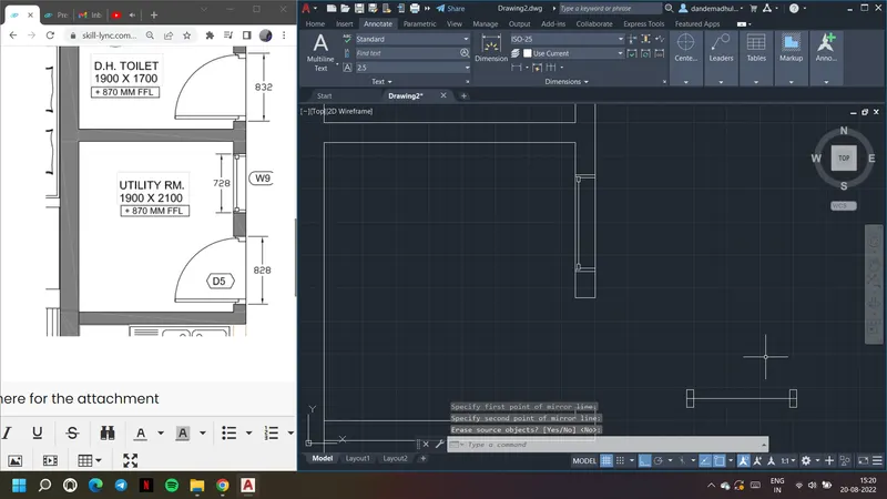
10. For drawing door, first draw a rectagnle and a line with length equal to width of the door i.e., 828 units.
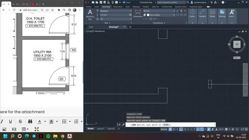
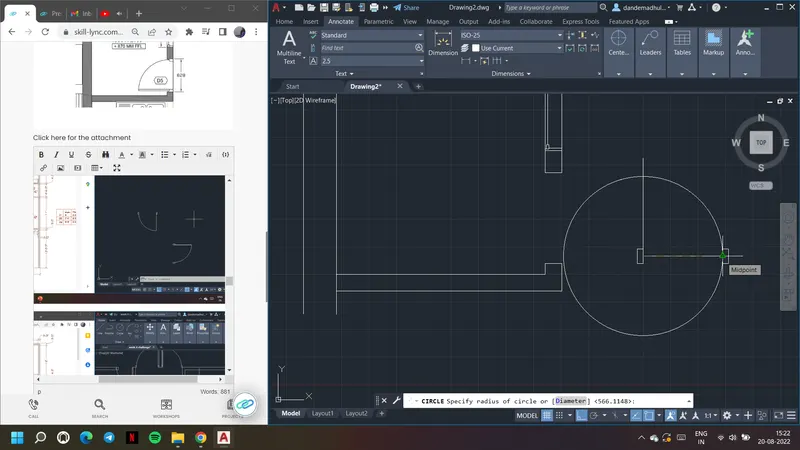
11. Draw hinge with 1 unit and a line with panel thickness 1.5 units. Use circle comamnd and draw circle with center and radius.
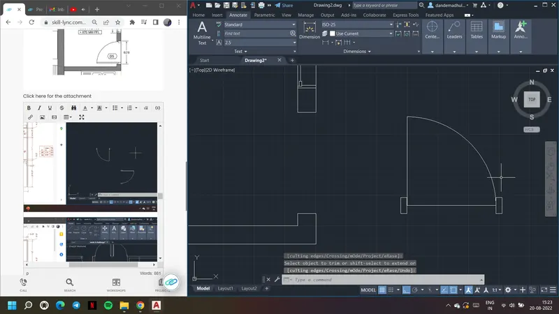
12. Trim the extra parts to form the door.
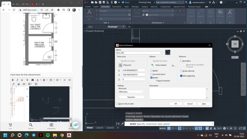
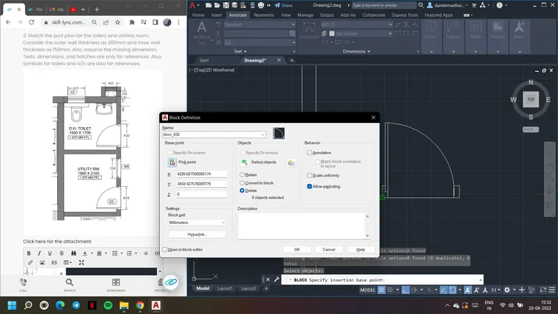
13. Create block, give block command, select object and pick point
14. Use Bedit command to edit the block as shown below.
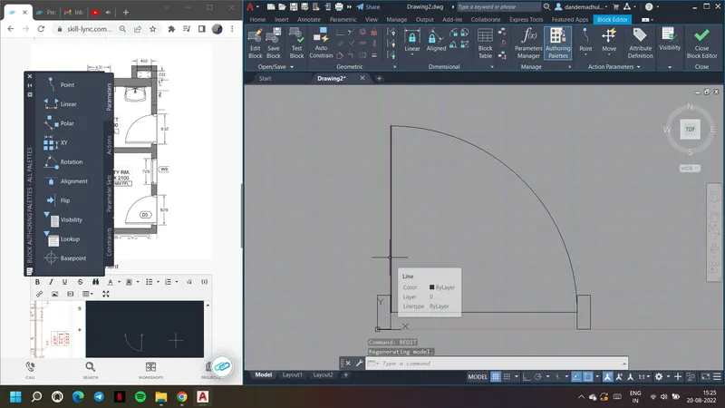
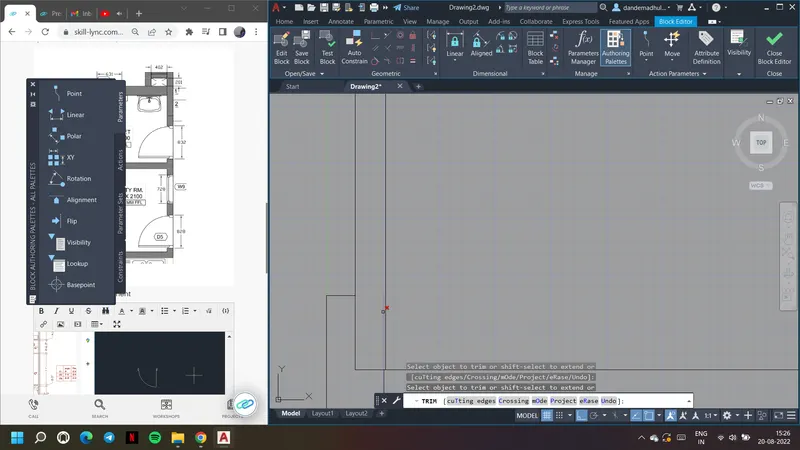
15. Save it to change the changes to the block.
16. Similarly create another door with 832 door width
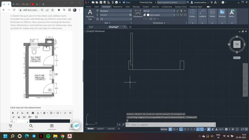
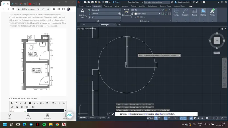
17. Use insert option to insert the created doors. Use rotate option while inserting to rotate the object as required.
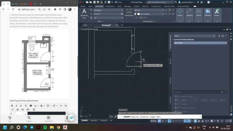
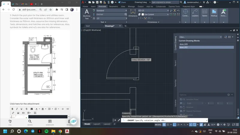
18. Insert doors at mentioned places
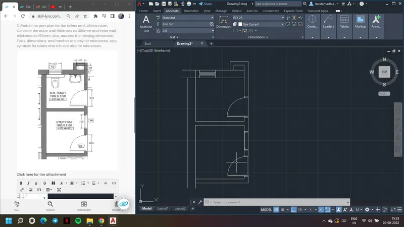
19. Draw toilet using rectangle command. Offset command and fillet command as shown below
20. First draw the rectangles as shown
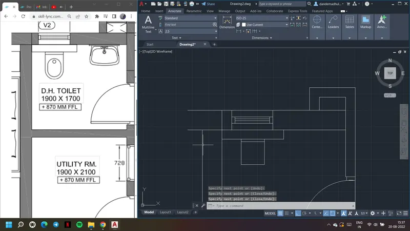
21. Use circle comamnd and trim it to form the arc at end of rectangle
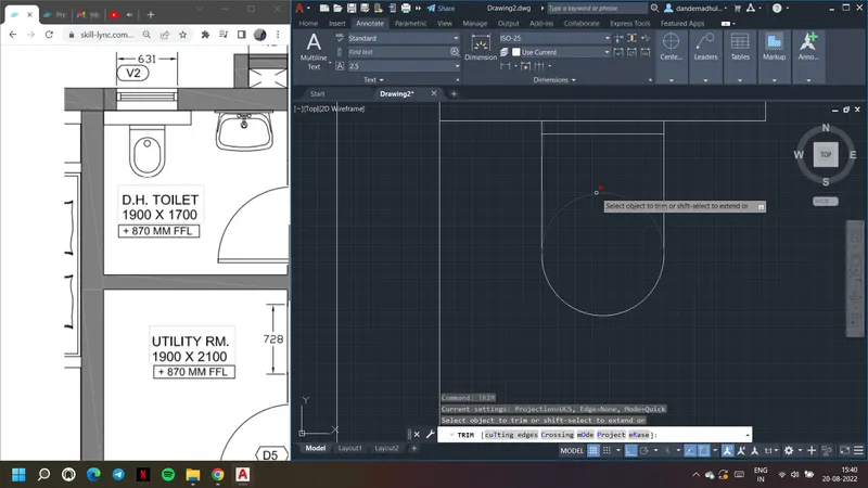
22. Use offset comamnd and offset distance as 50 units and draw the inside part as shown.
23. Use circle command and draw arc at other end
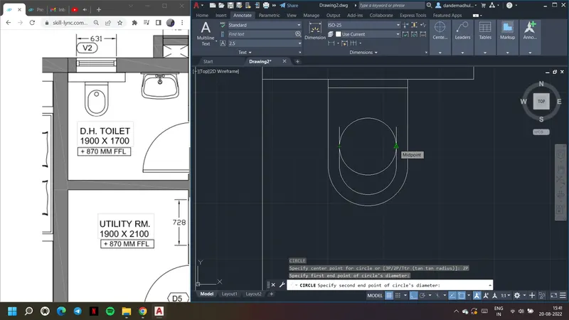
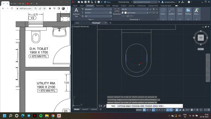
24. Trim the extra parts using trim command
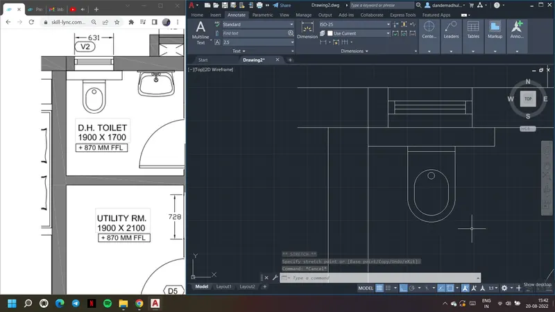
25. Draw a trapezium and use arc command to draw arcs at both ends of sink
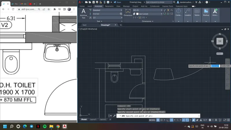
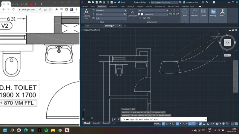
26. Trim the extra parts as shown and draw a line at both sides using line command
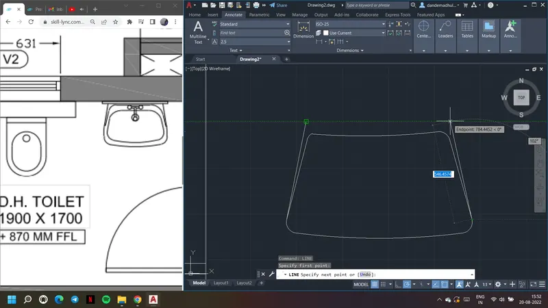
27. Use scale comamdn to decrease the size of the drawn sink
28. Select object and decrease the size as required
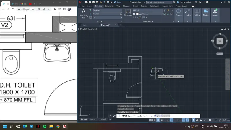
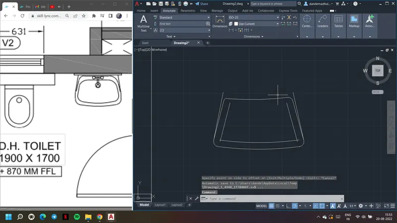
29. Use offset command and draw inside part of sink
30. Use fillet option and radius as 50 units to curvet the edges
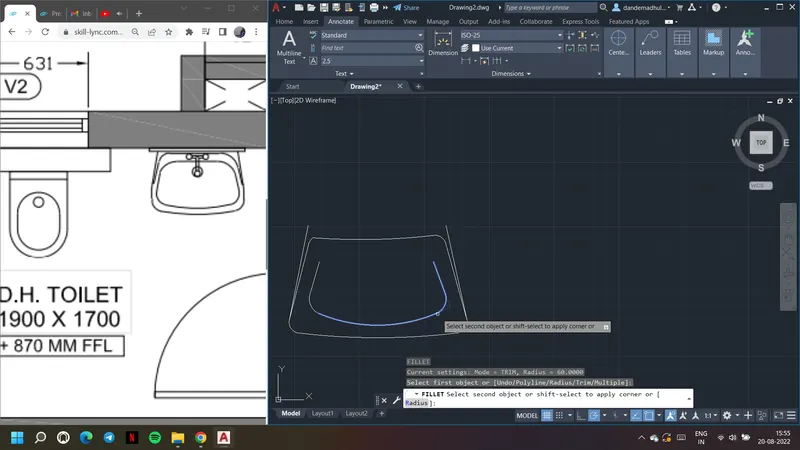
31. Use arc command and finish the inside part by drawing an arc and trimming it
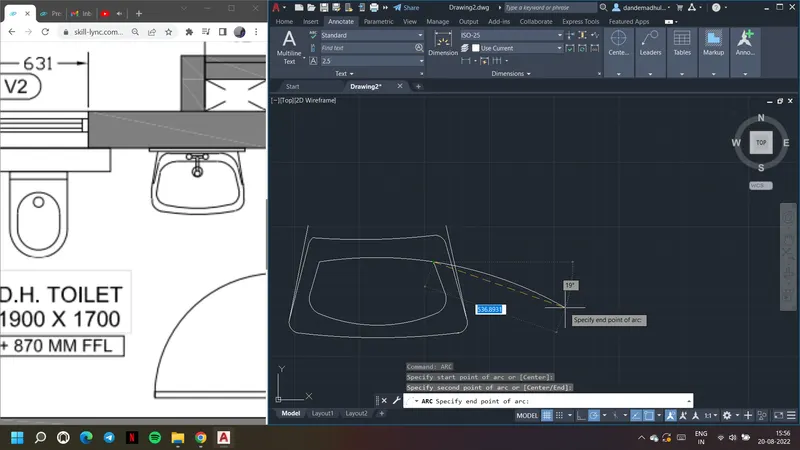
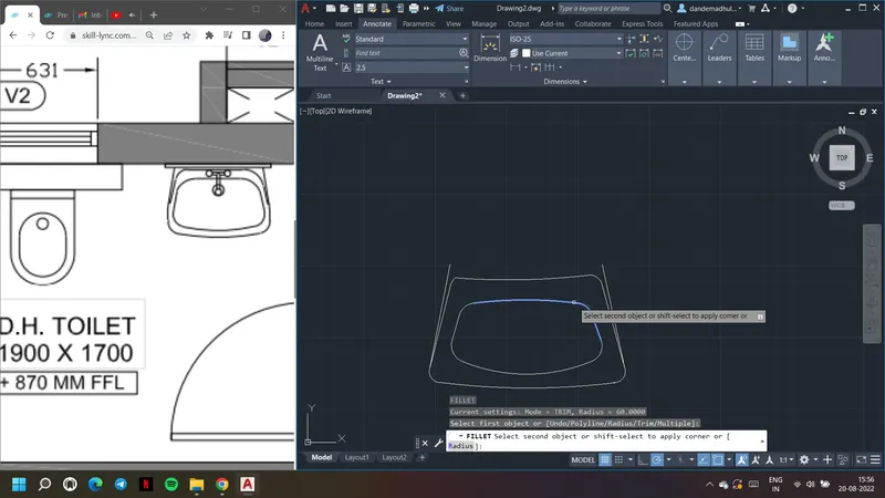
32. Use circle command and draw circles and lines to form shapes as taps
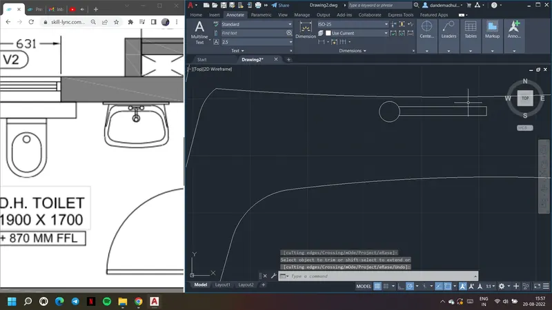
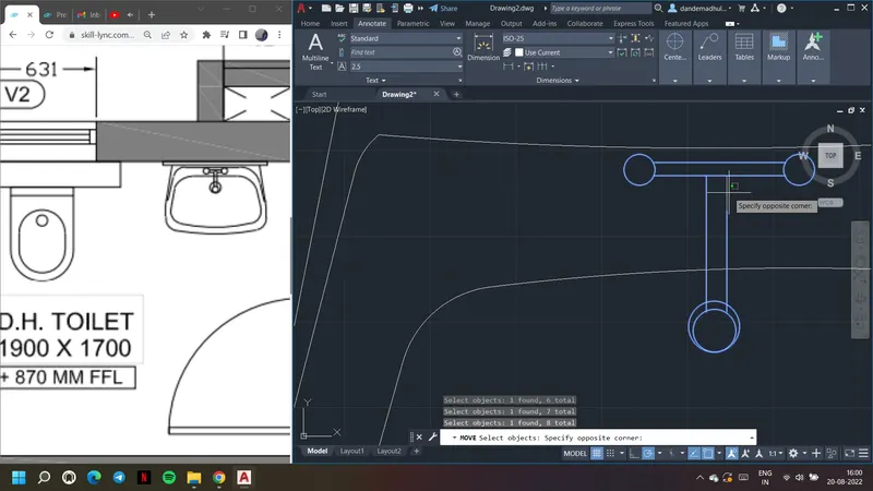
33. Move tthe sink to the toilet room using move command
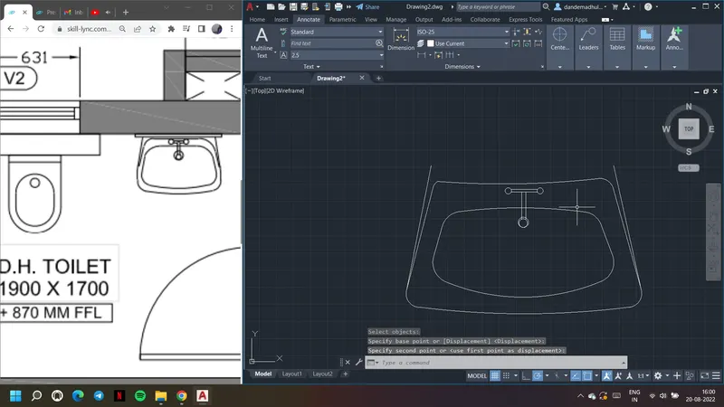
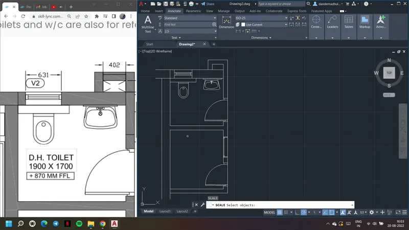
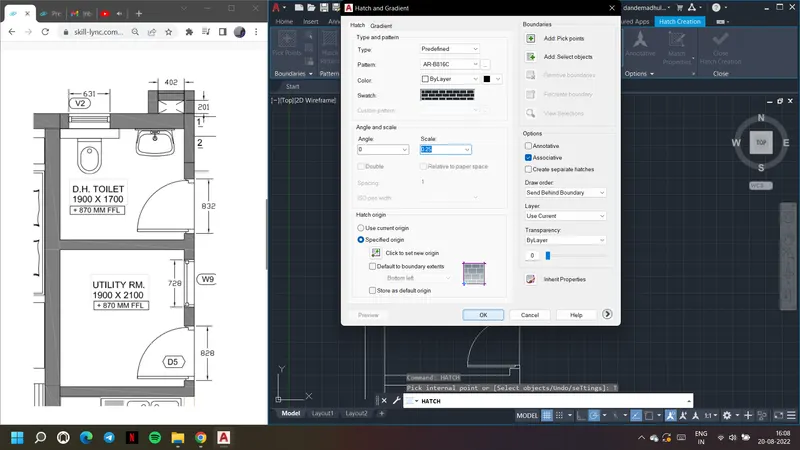
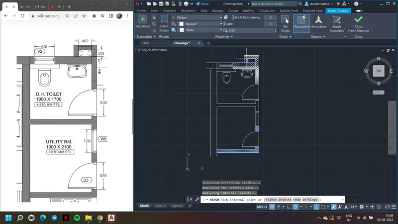
34. Use hatch option to hatch the walls. Use hatch settings if needed and set the scale as required
35. Use dimlinear and text command to measure the length and name the rooms
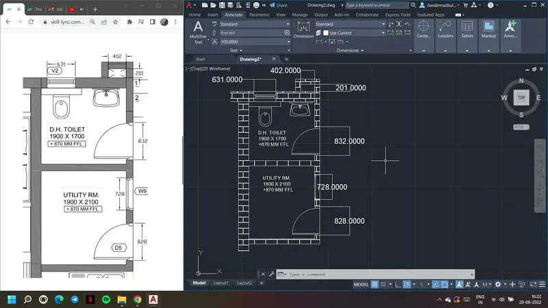
Result:
Part plan for the toilers and utilities room