Creating a Wardrobe detailed drawing, Floor Plan, Kitchen Layout and Column Detail using AutoCad
Aim & Introduction: To draw elevation and details of a wardrobe. To use layers command to provide dimensions and text to the drawing. To draw front view, cascasde view and side view of the wardrobe. Every detail of wadrobe is drawn for clear understanding of drawing as mentioned.
Procedure:
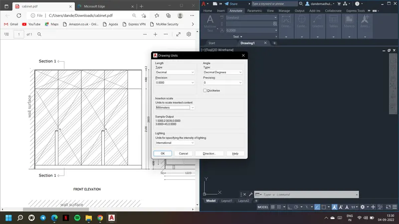
1. Open the AutoCAD drawing and give command units. Choose units as decimal and millimeters as shown.
2. First drawing the plan. We can also draw front elevation and from that we can draw the plan.
3. Draw a rectangle with the given dimensions. Use line command and ortho mode and given distances to form a rectangle.
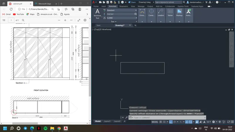
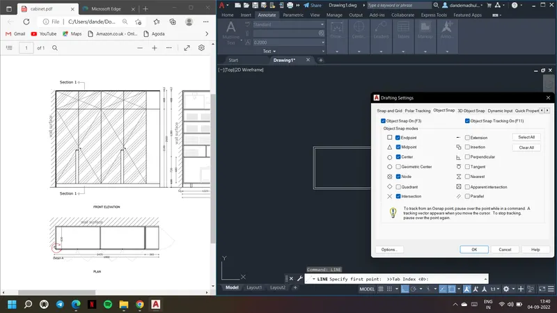
4. Go to object snap setting to set the required snap options. Use offset command and offset the drawn rectangle.
5. Use trim and line commands and change the drawn rectangle by making openings as shown whereever doors of wadrobes comes.
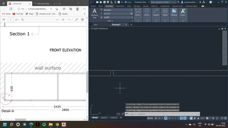
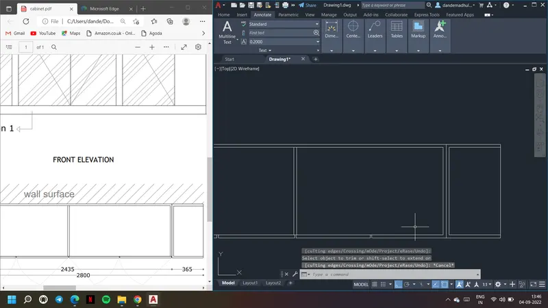
6. Use hatch command and hatch the wall surface. First from a closed rectangle, after hatching delete the rectangle.
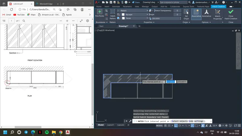
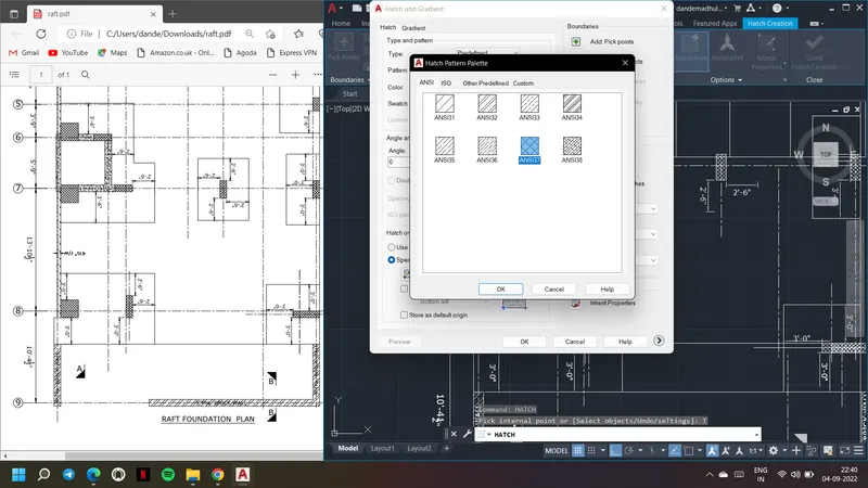
7. Go to hatch settings. Choose hatch type and scale as per the requirement.
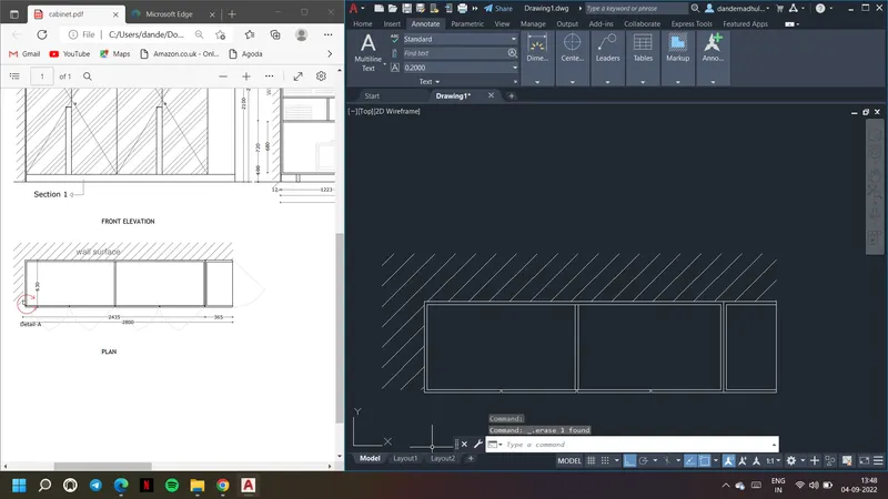
8. Now to draw elevation, use plan and elevate it to form front elevation.
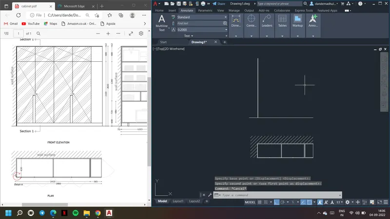
9. Elevate using line comamnd whereas required to form wadrobe.
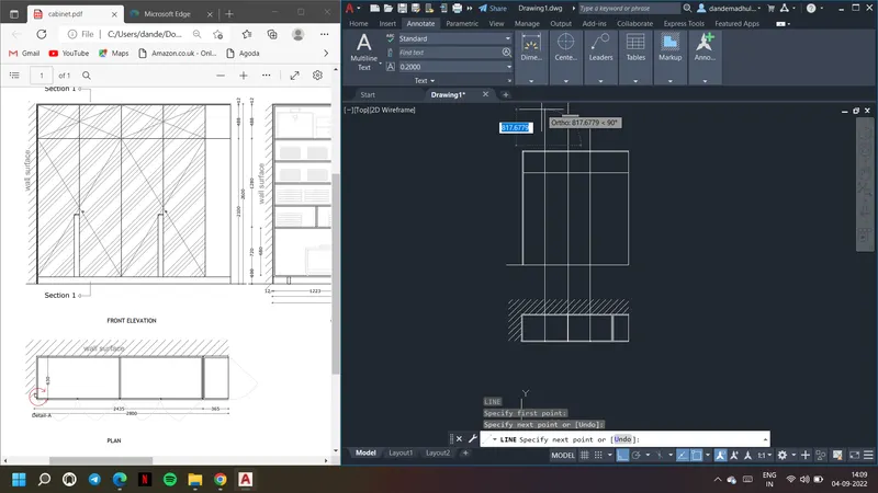
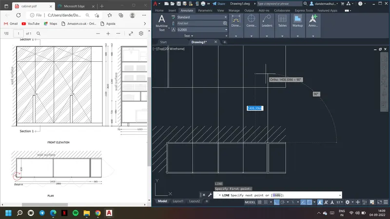
10. To draw door choose line comamnd and ortho mode. Assume the dimensions and draw the doors.
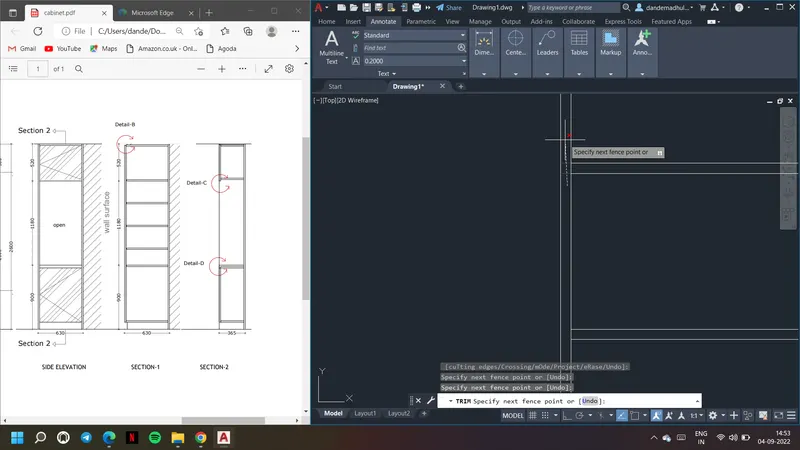
11. Use trim comamnd to trim the extra parts.
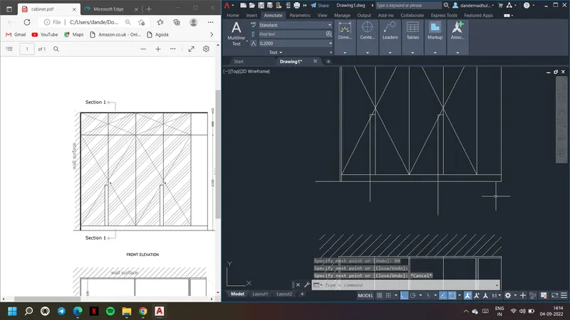
12. Use hatch command and hatch the wadrobe by going to hatch settings and choosing hatch type.
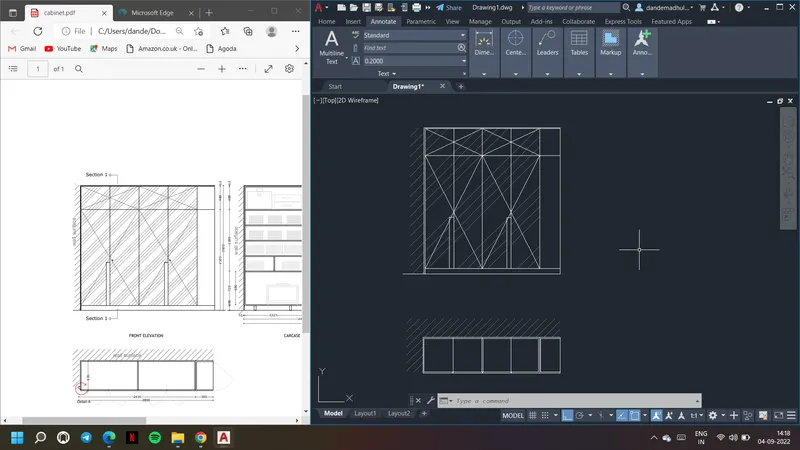
13. To draw cascade view make use of front elevation and extend the drawing.
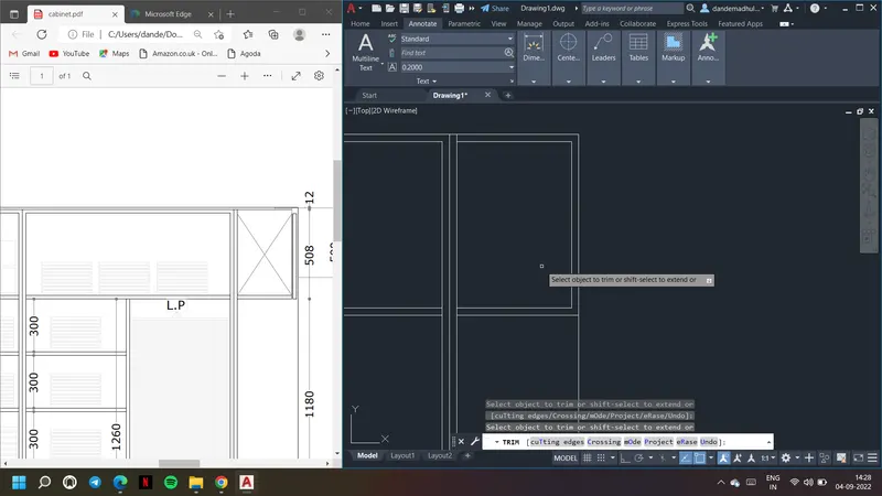
14. Use offset command and offset all the lines drawn.
15. Trim the extra parts using trim command.
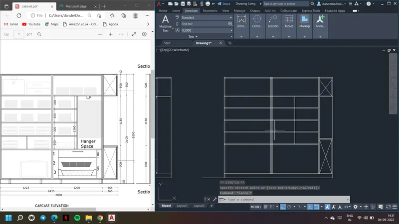
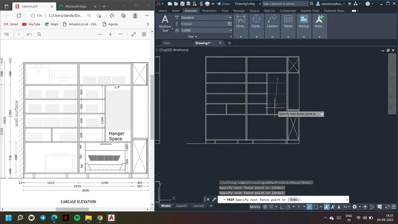
16. Draw hanger space and drawer as shown.
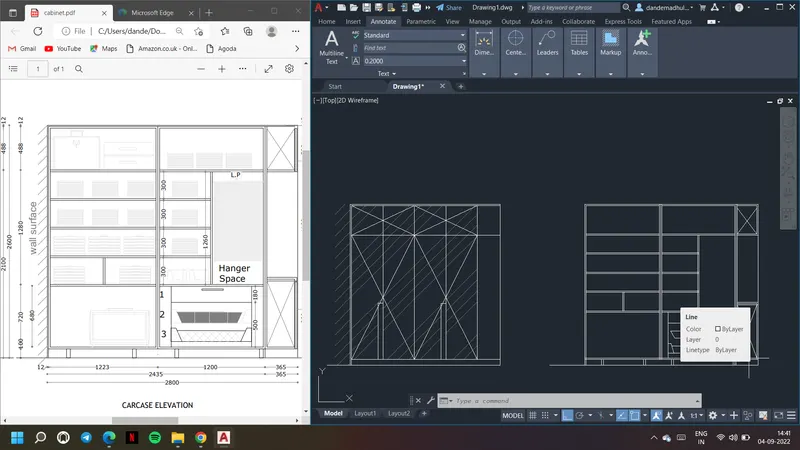
17. Use hatch command and hatch the portions whereever required.
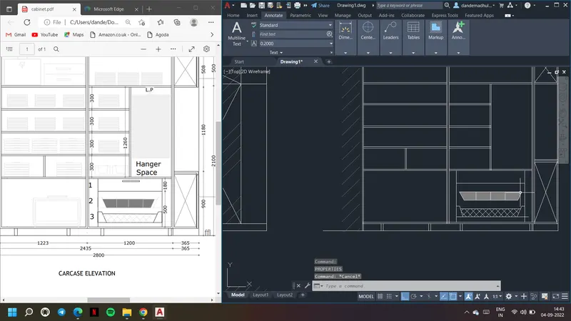
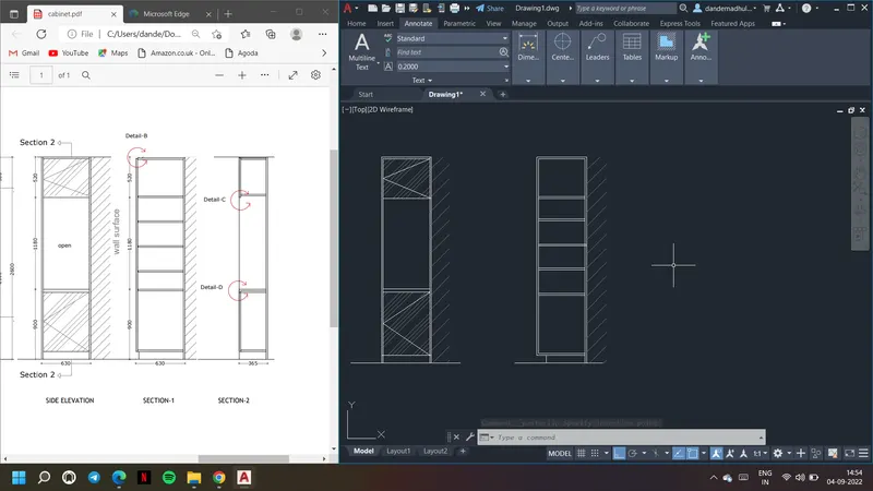
18. NOw using fromt and cascade elevation draw side elevation, section 1 and section 2.
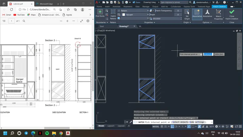
19. Hatch the required portions.
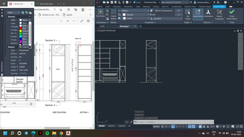
20. Make use of cascade elevation and draw section 1 as shown.
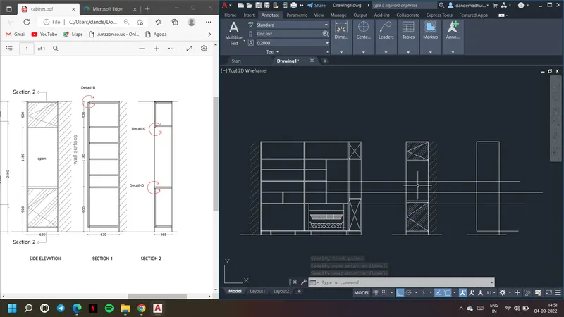
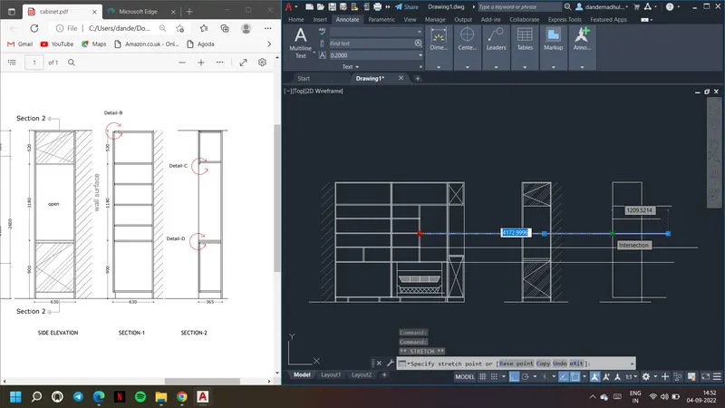
21. Remove all the extra parts using trim command.
22. Use dimilinear command to show the dimensions.
23. Go to layers by giving layer command. Create new name it as dimensions and using dimlinear command give dimensions.
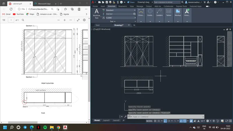
24. Draw section 2, use offset comamnd whereever required.
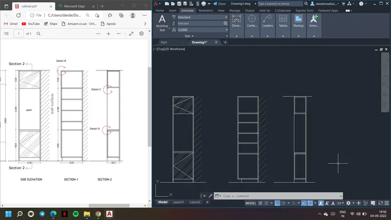
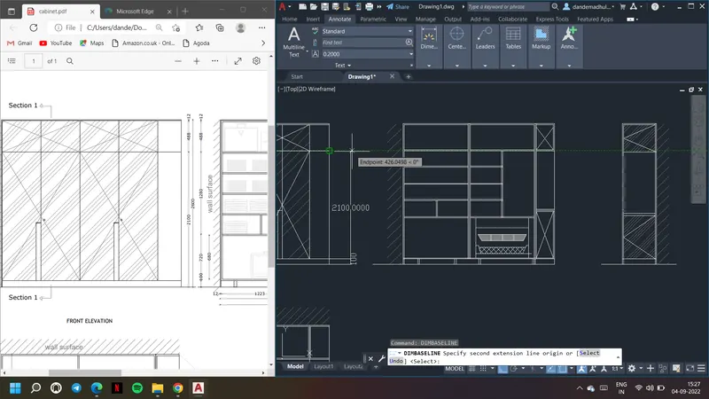
25. Use dimbaseline command to show measure dimension from the base line.
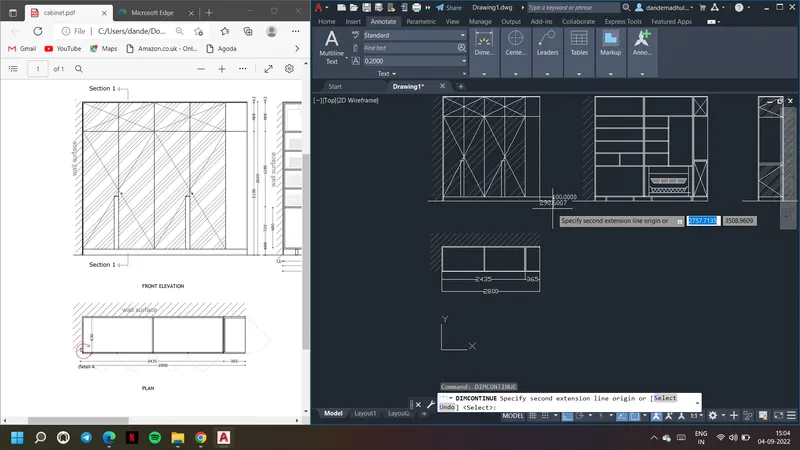
26. Use angle option in dimlinear to rotate the text or dimension.
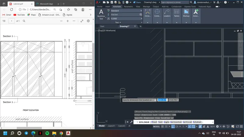
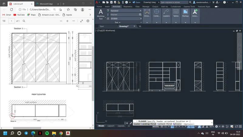
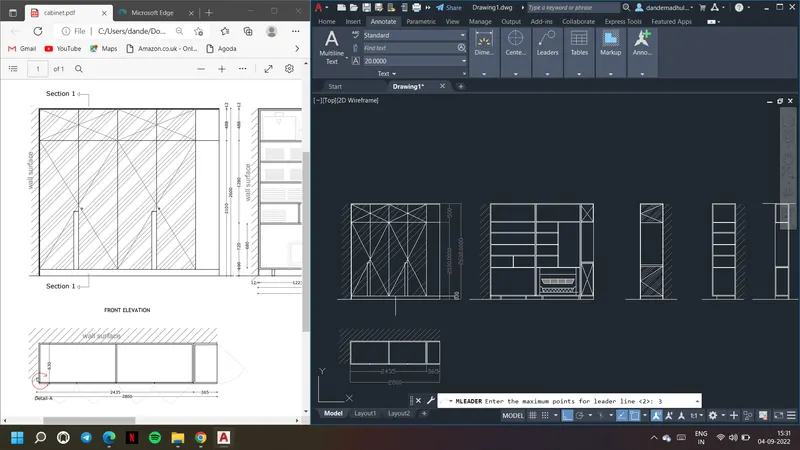
27. Use multileader to draw the leader as shown. Choose options like maximum points, arrowhead direction.
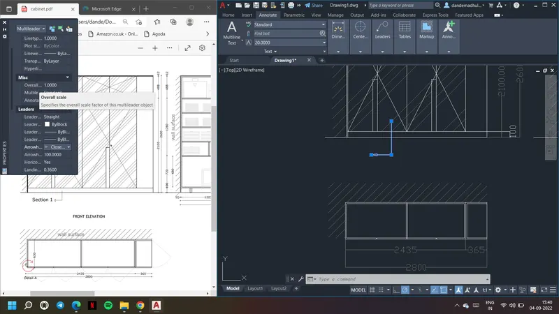
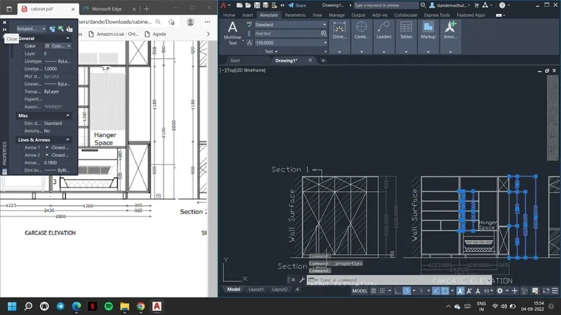
28. Can also go to properties and change the arrowhead as required.
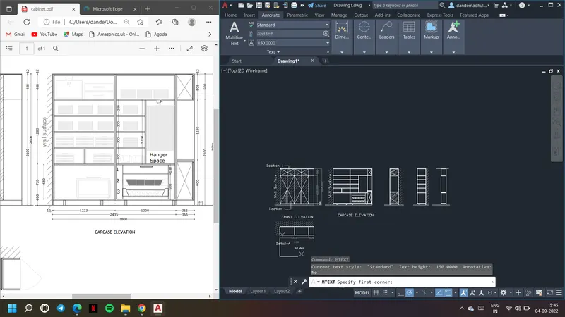
29. Use Mtext or text command to name the drawings as shown
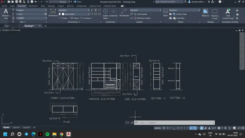
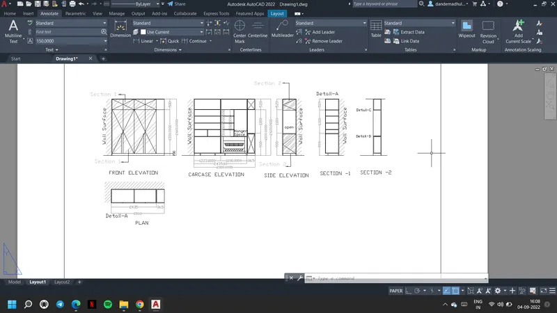
Result: Elevation and details of a wardrobe
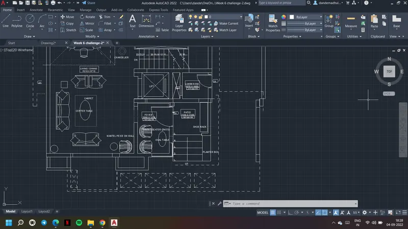
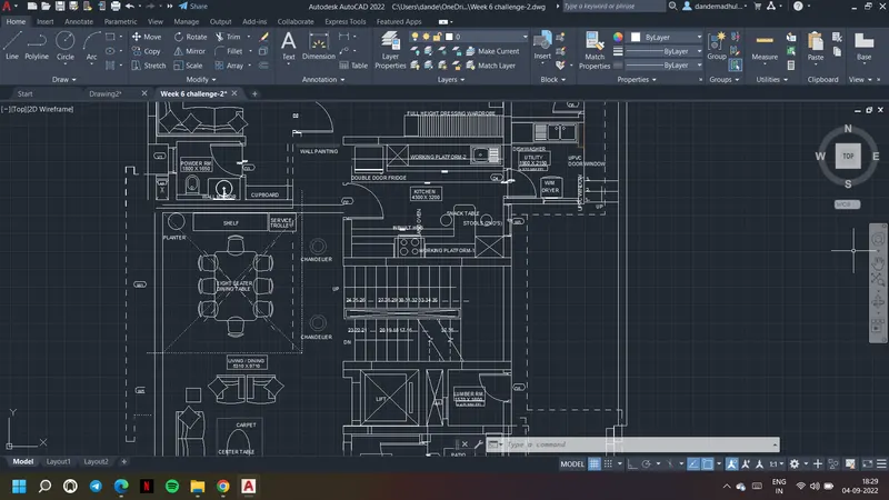
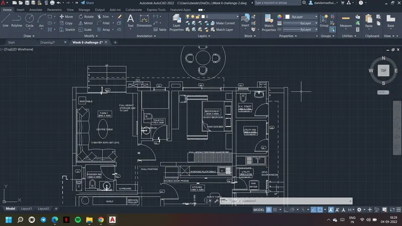
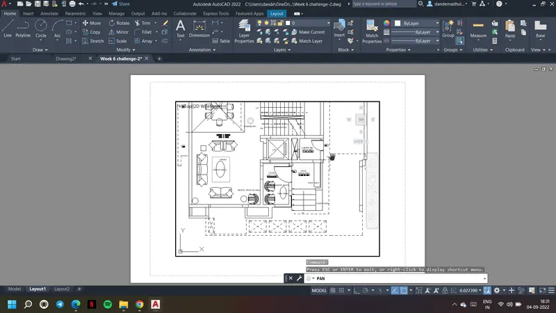
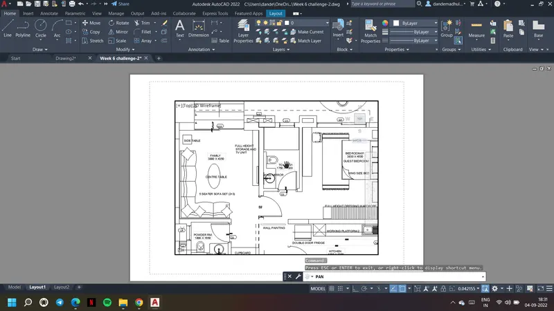
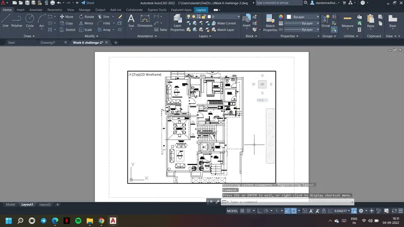
Aim & Introduction: To draw floor plan of a building. Size of doors and windows are assumed. Exterior wall thickness is taken as 230 mm and interior wall thickness is taken as 150 mm. Stairs thread is taken as 300 mm and riser as 150 mm. Text and dimensions are inserted accordingly using comamnds.
Procedure:
1. Open the AutoCAD drawing and give command units. Choose units as decimal and millimeters as shown.
2. Draw living room using rectangle command and using given living room dimensions.
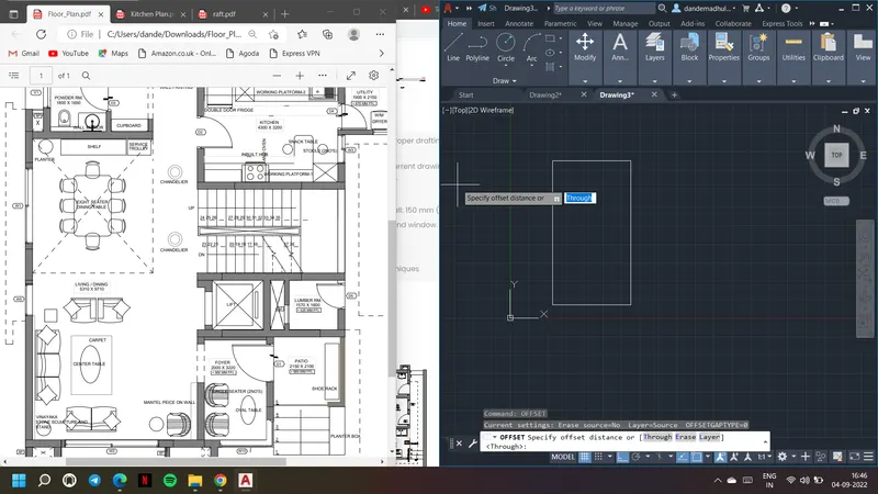
3. Offset the rectangle giving offset distance as 230 mm as it is exterior wall.
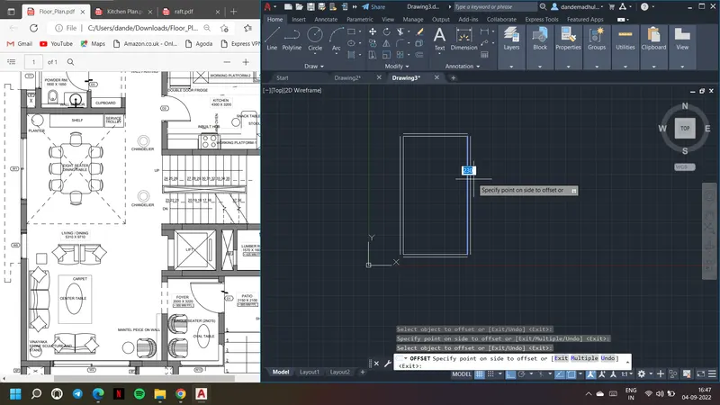
4. Use fillet command and fillet the edges of the living room.
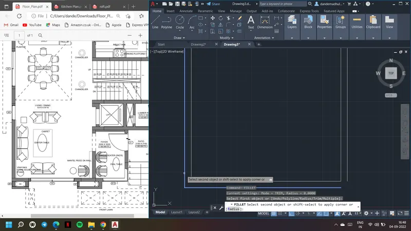
5. Use line command, ortho mode and draw the outer area of living room.
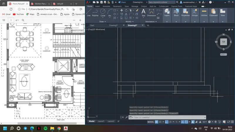
6. Use trim command to remove the extra parts
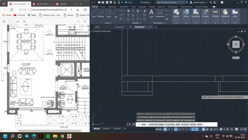
7. Use line command and draw Foyer room. Use offset command to offset it to 230 mm.
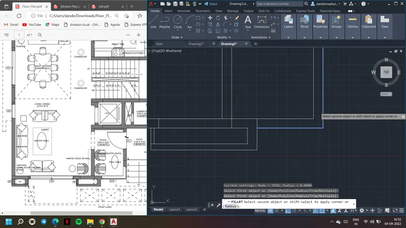
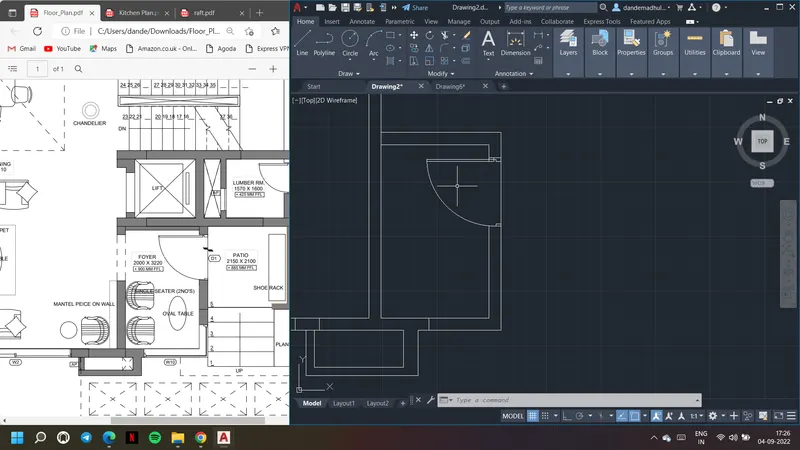
8. Import the floor plan pdf file into the drawing and create a block for the door.
9. Insert this block into the drawing and scale it as required using scale command.
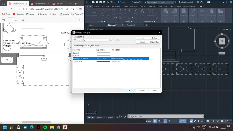
10. Go to linetype and load the required linetype. Set it current to use that.
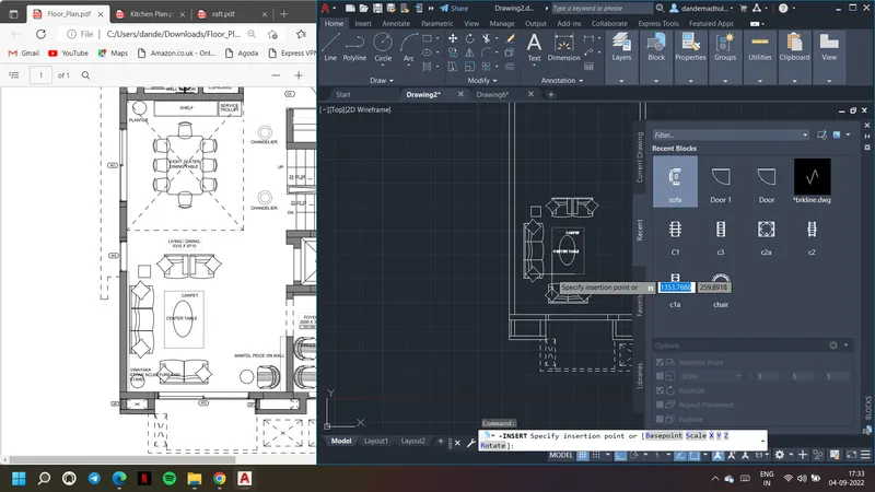
11. Use block comamnd and create block for other furniture like sofa, table, chairs.
12. Insert them in the drawing using insert comamnd and sclae them accordingly using scale comamnd.
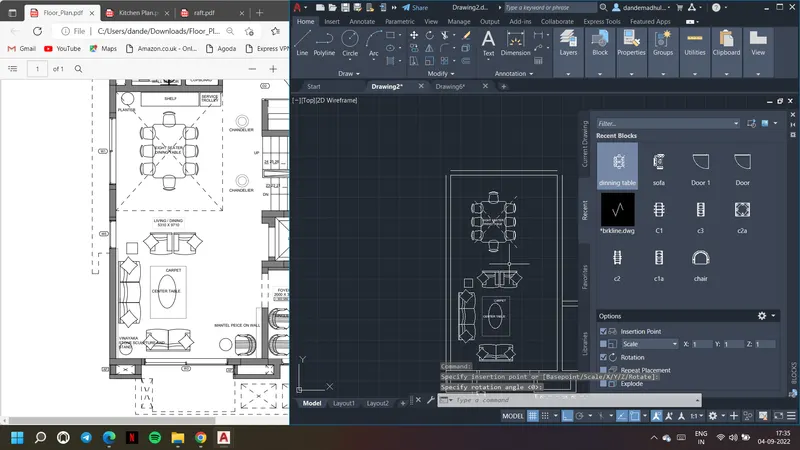
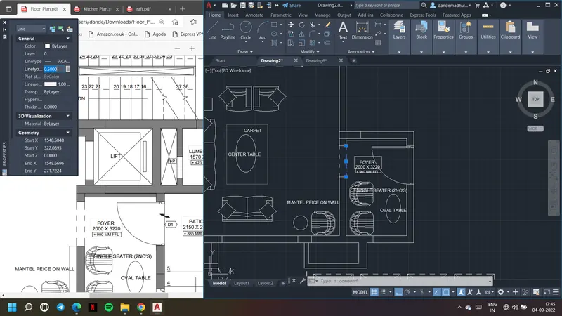
13. Similarly draw the utility room, bedroom, lift and stairs.
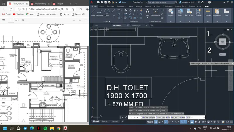
14. Use text command to form the text and to name the each room.
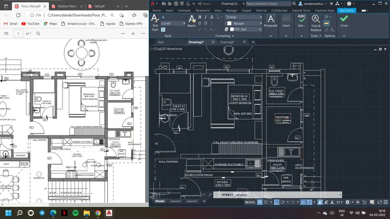
15. Name each and every room and furniture for better understanding of the drawing.
16. Copy the text and edit it using Tedit comamnd.
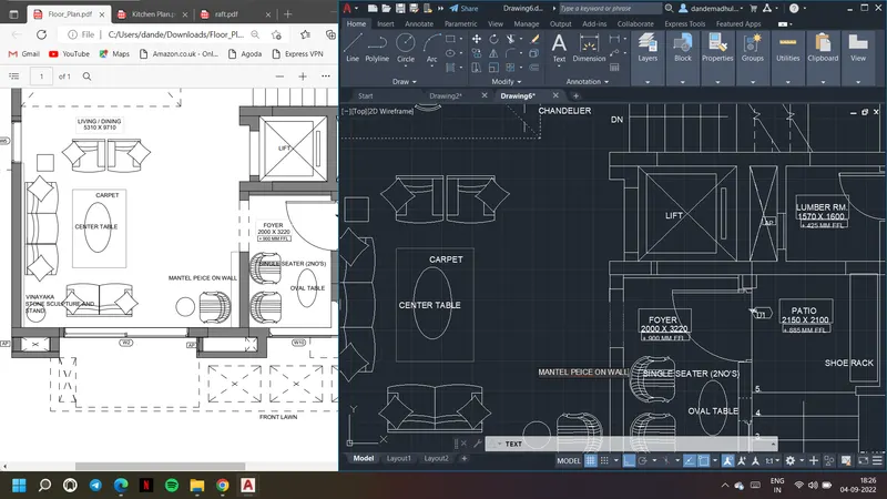
Result: Drawing of the Floor Plan
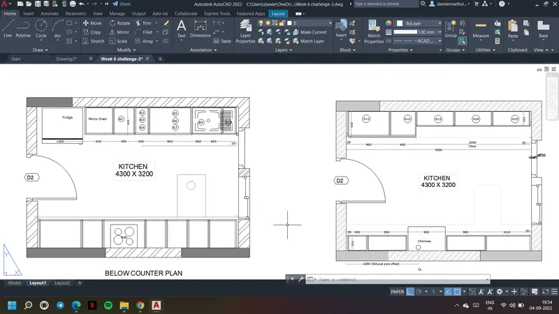
Aim & Introduction: To draw kitchen layout of a building. Below counter plan and above counter plan both are drawn. Text and dimensions are inserted accordingly using comamnds.
Procedure:
1. Open the AutoCAD drawing and give command units. Choose units as decimal and millimeters as shown.
2. Draw below counter plan first using line command. Draw the lines with respective distances as given.
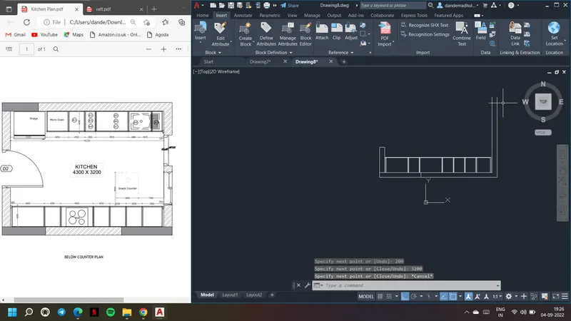
3. Offset them using offset command.
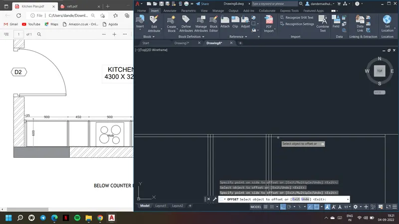
4. Draw the outer layer i.e.,layout of kitchen as shown
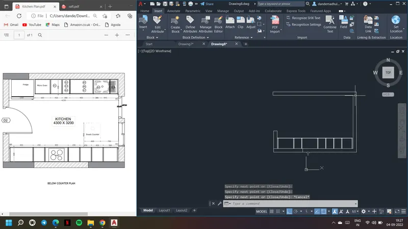
5. Import kitchen layout pdf and crate block for the door.
6. Insert the door into the drawing. Use scale command and sclae the imported door as required.
7. Else draw a door and create a block for that and insert it.
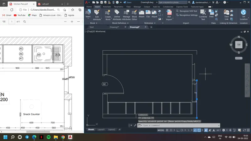
8. Chnage the linetype and set it as current and draw snack counter as shown.
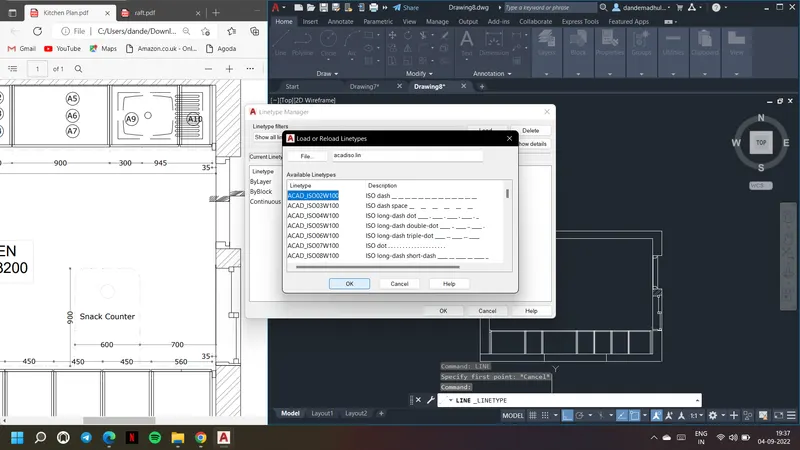
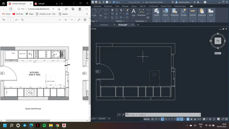
9. Draw all other parts of kitchen i.e., fridge micro oven etc.
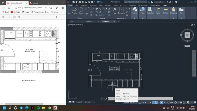
10. Use dimlinear or dimcontinue to show the measurements/ dimensions. Use Mtext or text comamnd and provide the text wherever required.
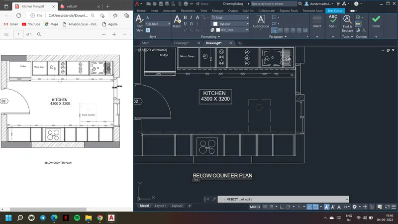
11. Use hatch command. Go to hatch settings to choose hatch type and scale. Provide hatch wherever required.
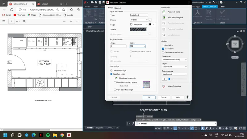
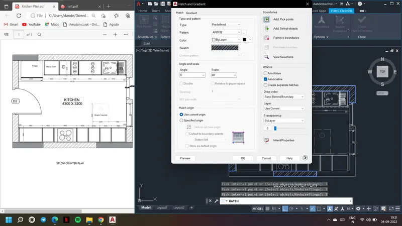
12. Can also got to properties and set the scale of the hatch as shown.
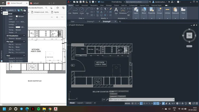
13. Copy the below counter part of kitchen drawn. Paste it and edit it accordingly to form the above counter part of kitchen as shown.
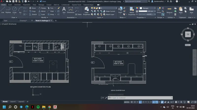
Result: Drawing of the Kitchen Layout
Aim & Introduction: To draw columns details. Text and dimensions are inserted accordingly using comamnds. Bars are drawn accoridngly with the sizes given in the schedule.
Procedure:
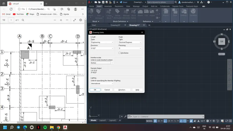
1. Open the AutoCAD drawing and give command units. Choose units as engineering and inches as shown.
2. Draw a rectangle and divide it to form the schedule of columns as shown using line comamnd and ortho mode.
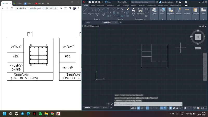
3. Use Mtext or text command to provide text as shown. Use %%c to get the symbol of diameter in text.
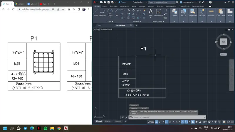
4. Copy this P1 column scheule and paste it to form P2 and P3 column schedule.
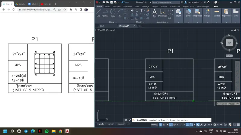
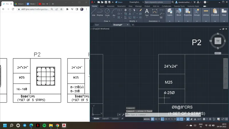
5.Use Tedit and edit the text in P2 and P3 column schedule
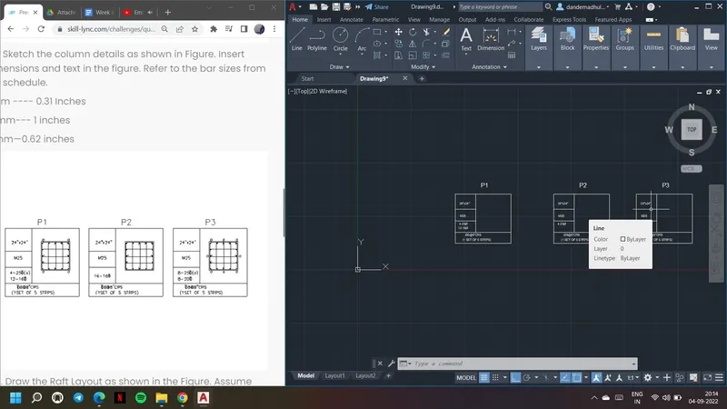
6. Now to draw columns draw a reactangle and offset it as shown.
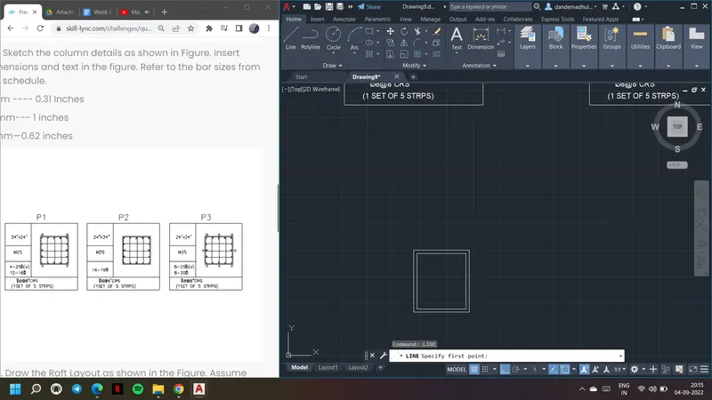
7. Divide the side of rectangle into four parts using divide command.
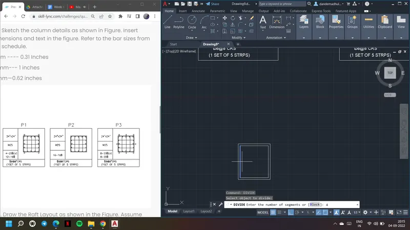
8. Use Ptype command to choose point style.
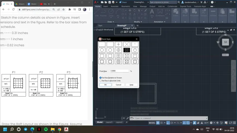
9. Draw lines at the points and delete the points. Similarly draw vertical lines by dividing it into four parts.
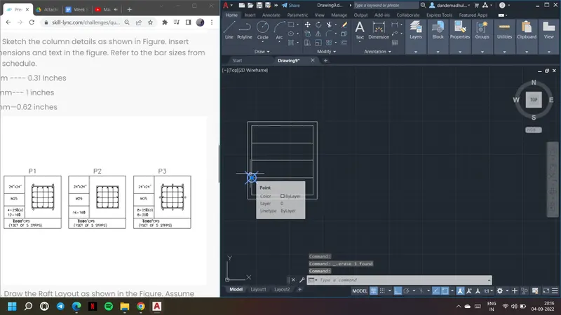
10. Draw the bars with given diameter using circle command.
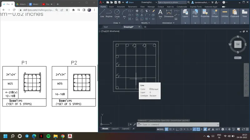
11. Use mirror command and mirror them the other side of column
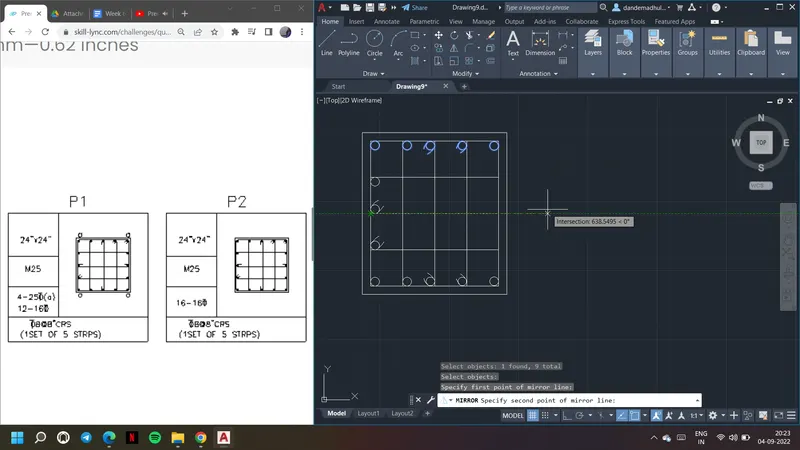
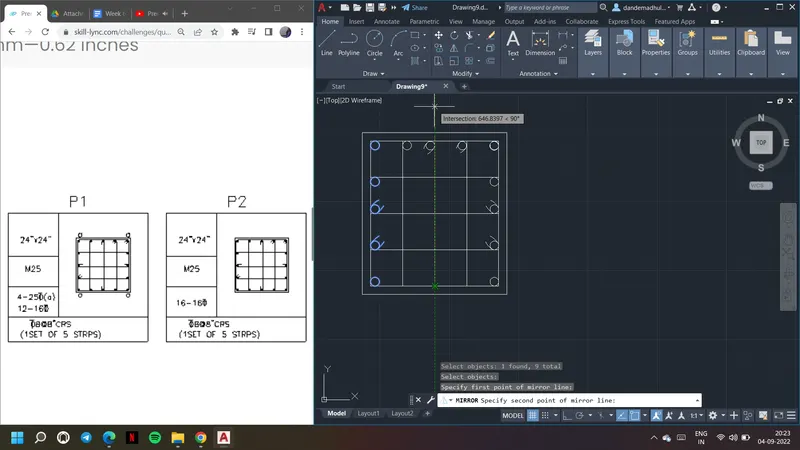
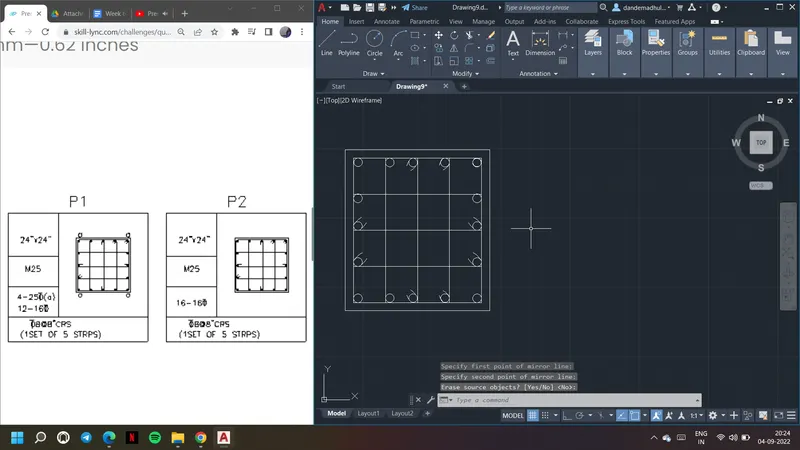
12. Copy this P1 column and paste it to form P2 and P3 columns
13. Now edit them for P1 column draw the circles as shown, four 25mm diameter bars.
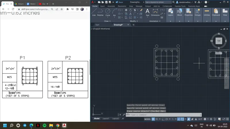
14. For P3 column draw eight 25mm diameter bars as shown

15. Create blocks for them and insert in the column schedule.
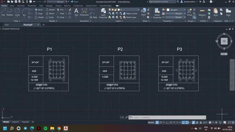
Result: Sketch of Column Details
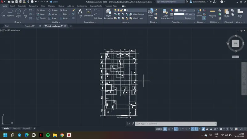
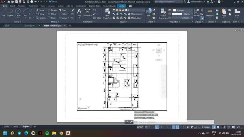
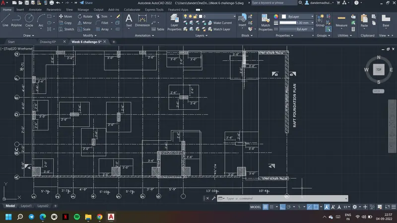
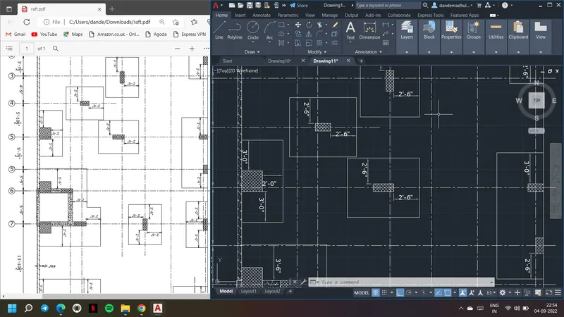
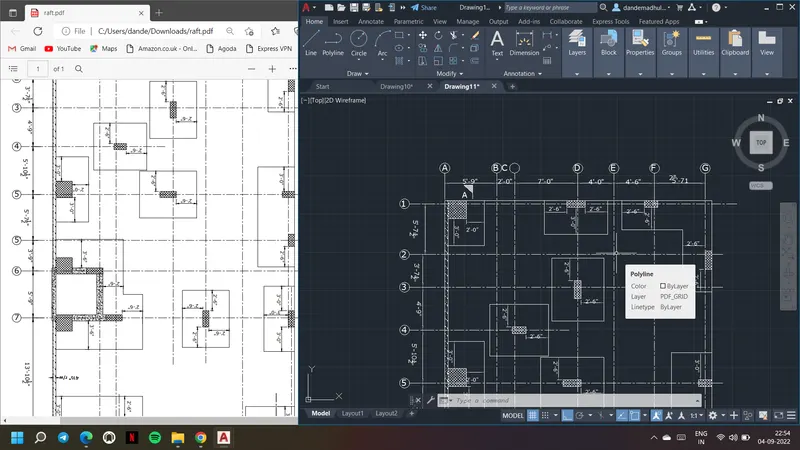
Aim & Introduction: To draw the raft layout. Sizes of columns are taken as 24”x24”, 9” x 24”, 9” x 18”vand 9’ x 24” respectively. Text and dimensions are inserted accordingly using comamnds.
Procedure:
1. Open the AutoCAD drawing and give command units. Choose units as engineering and inches as shown.
2. Line type is choosen accordingly by loading the required one. Set is as current to get it in the drawing.
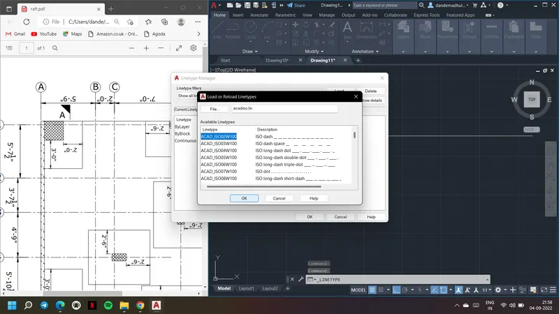
3. Use line comamnd and respective distances and draw the grids as shown.
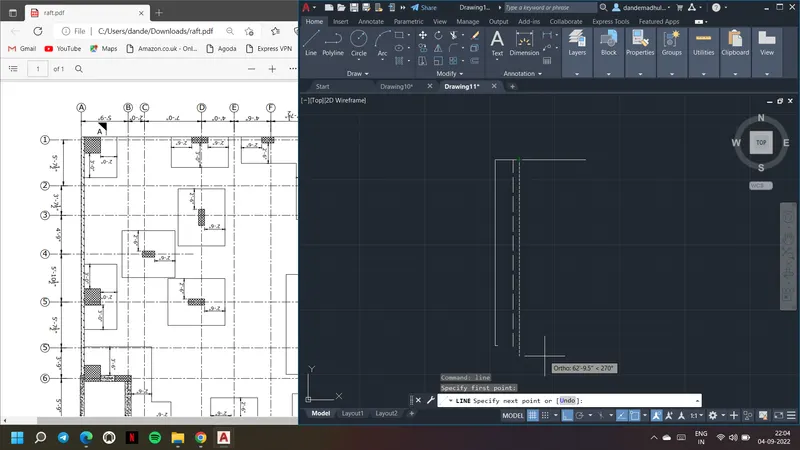
4. First draw grids to make the drawing easier. Use linestype as shown and form grids.
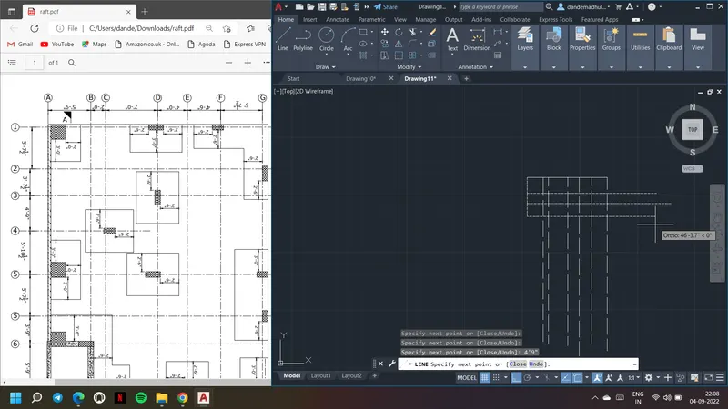
5. Extend all the grids and trim the extra parts to form raft layout as shown.
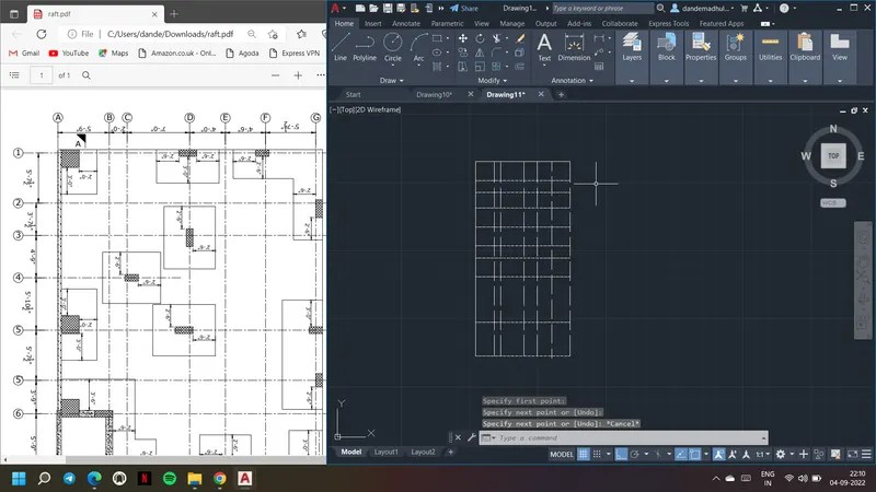
6. Draw the columns from bottom in each grid one by one.
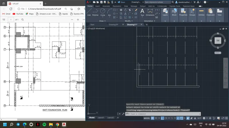
7. At grid 9 draw brick wall and use hatch comamnd to hatch it.
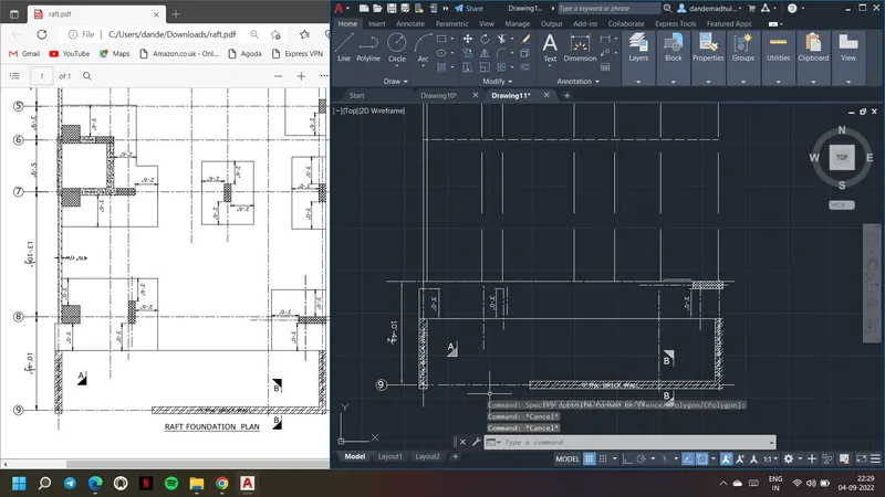
8. Use hatch settings to select hatch type and scale.
9. Now in grid 8 draw the columns accordingly. Use hacth comamnd to hatch them.
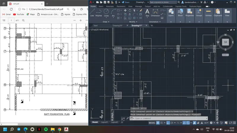
10. Similarly draw the columns in every grid to form the raft layout.
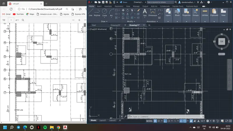
11. By taking grids as reference finish the raft layout.
12. Hatch every column with column hatch type. Also hatch the walls and brick wall accordingly.
Result: Drawing of Raft Layout