Creating Architectural and Structural model with 3D rendering using REVIT
1) Select the type of structure you want to build from one of the three below:
a. Multi-Unit Residential Apartment
b. Office Buildings
c. School
A.In the above structure i choose residential type.
because most of the occupants spent most of their life in this type structure.
rather than office and school the residental structure is the most important for common person.
school is comes under category education which is group B.
office building is come under commerical which is group F.
residential building come under group A.
while modelling Residential structure we need provide provision which given by the nbc.
nbc means national building code.
some standards are common for all structures.
ventilation
lightening
minimum space.
2) Assume reasonable assumptions for geographic and location details for your project modeling. Based on assumptions and type of structure selected identify the modeling requirements from NBC
A. while modelling Residential structure we need provide provision which given by the nbc.
NBC was originated in the year 1980 after so many amandaments latest 2016 newly amandament book established.
while designing and practing in the construction we have to follow the nattional building code standards.
i have revised some parts and sections in that book.
group 1
group2
group4
griup 3
group1-construction planning.
group2-structural design
group 4-buiding service
group3-construction practices and safety.
my plot size is 36600sq.feet (3360 sq.m)
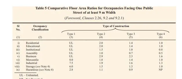
in my area (or) location floor space index value is ranges between 3-6
i take fsi value 3.
floor area ratio and floor space index both are same but we can distinguish them.
floor space index is expressed in percentage.
floor area ratio is expressed in decimals.
when we seeing 2,1.5,2.5 these are all the floor space ratio.
floor area ratio=built up area(plinth area)/plot area.
built up area is the total floors area.
now my bulitup area is 3x3360 -(1hectare)
i split that area to make stlit+six floor residential building.
each floor i provided 16000sq.feet(1400 sq.m)
i provided 12 flats in each floor.
each flat area is 900 sq.feet.
i utilized the maximum space as per the nbc .
i left some portion area for low income housing maximum 150sq.feet
as per the nbc i followed some of the standards like.
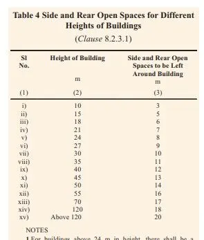
i provided front open space 3m.
i provided set back distance 7m(18-24 m high)
as per the nbc the building heigt is exceed 15 it is considered as high rise building.
my model is also hise rise building.
i follow the standards in which high rise buliding needs to maintain.
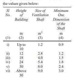
proper ventilation and lightening is provided to my model.
my model is abut to the road.
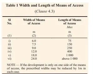
road width is 43' which is greater the 12m .
as per the rule i can provided the premium fsi 30% to my model.
extra space i can provide .
i have followed accessibilty provisions.
i followed the room requirements which is greater than the minimum space.
3.Aim: To create residential structure model which comprise of foundation,beams,floor,shafts.
software that i used-Rivet
procedure
take the structural template.
draw the grids lines according to the plan.
place the footing on the grids.
33A,29A,32A,31A,30A,30B,29B,33C,32C,33D,32D,31D,30D,30E,33F,29F.
for 600 sqfeet appromately 10 columns have to place.
each flat is 900 sqfeet i place the 12 columns for single flat copy it to the others.
i choose the stepped foundation for my model because it has to transfer heavy load.
some location i used strip foundation for support purpose.
first footing size 3'4x3'4".
second footing size 3'x3'x1'.
thrid footing size 2'6"x 2'6"x1'.
place the structural column on the foundation.
size 9"x9" up to the ground floor.
i set the levels like this
foundation level-7'
ground level-0
first level +10'
second level+10'
up to roof level+10'.
for the matching to the road level i placed the plinth beam.
size9"x1'
placing beams on the grids (or)simply take line connects the columns.
after completion one portion copy to the others.
provide the foundation slab with the thickness 4".
extended the columns up to the first floor.(top constraint).
place the primary beams to the first floor with size 9"x1'.
connect to the columns.
place slab over the beams with thickness 6".
copy entire floor by using copycliboard.paste it to another levels 2,3,4,5,6.
provide floor to the balcony,shaft after completing of the architectural model.
i have done the architectural model before structural model so
mark the staircase and elevator position in the first floor .
take shaft tool set the base constraint is ground floor with 1'6" base offset.
top constraint is sixth floor with offset o'.
same procedure is repeated for the staircase shafting.
shaft is the verical cutting tool host are the floor,ceiling.
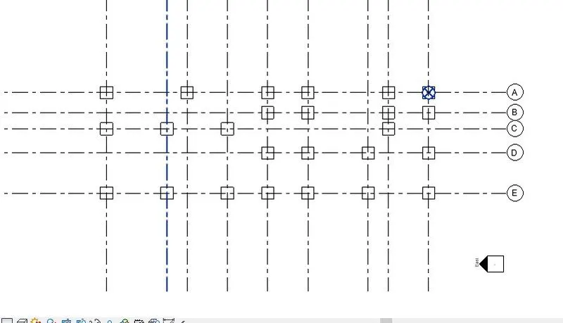

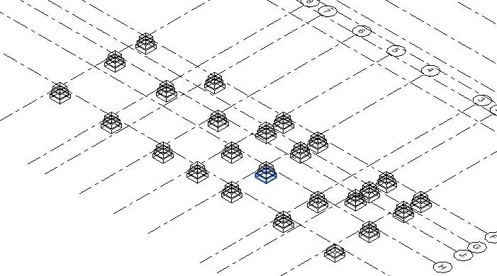
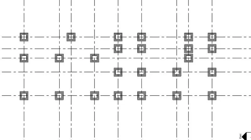
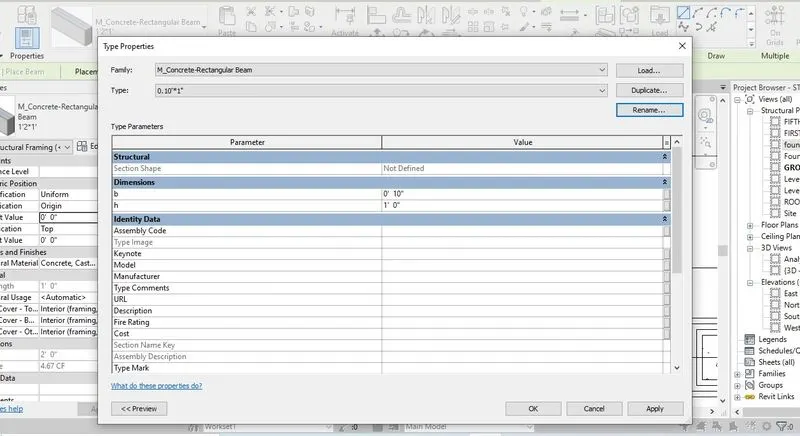
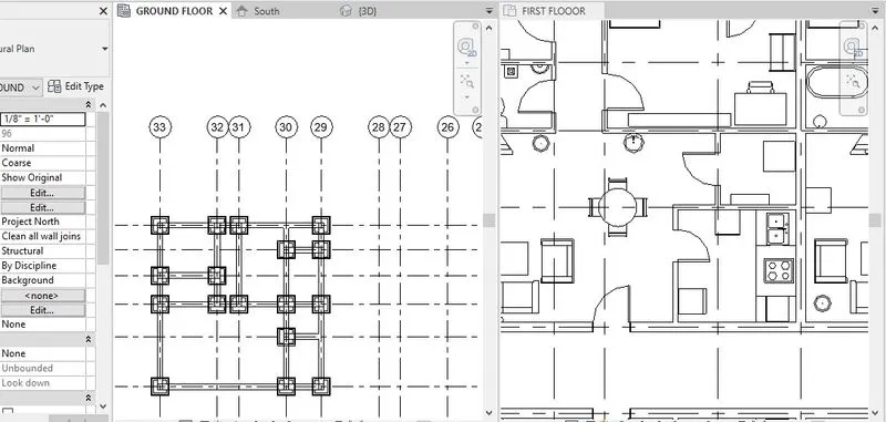
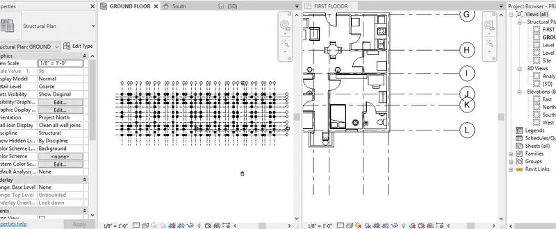
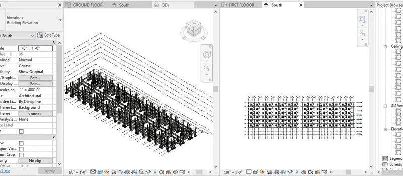
Result: I have created residential structure model which comprise of foundation,beams,floor,shafts.
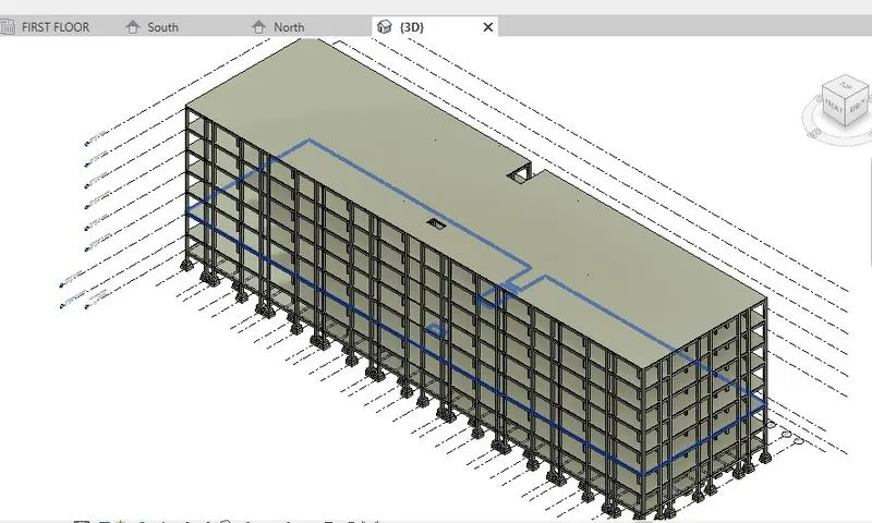
4.Aim: To create residential architectural model which comprise of walls,components .
software that i used-Rivet
procedure
place the grids in the longitufinal and transverse direction according to the plan with accurate dimension.
set the first longitufinal and transverse grid coordination as 0 in north/south and o in east/west direction.
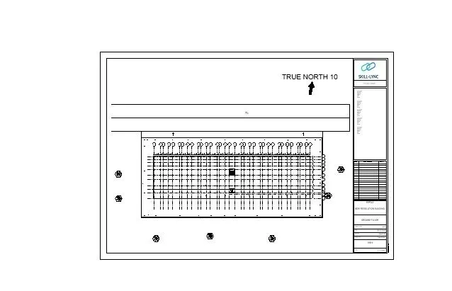
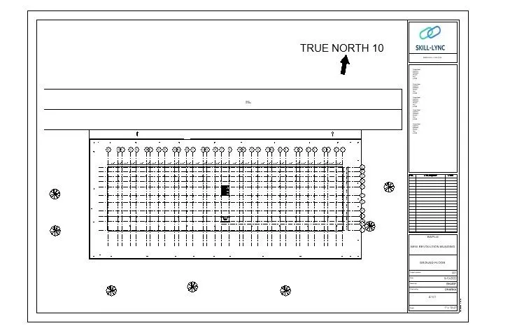
set the true north is 10 degree.
but while modeling set it as project north.
take architectural wall.
take pick line as the selecting tool.
select the grids which for the exterior wall.
draw only flat later copy it.
i choose line location- centerline
thickness9".
interior wall-4.5"
draw the interior wall according to the grids.
place the necessary components on the each rooms.
for ventilation ,lighting required no of windows,ventilators and doors are provided.
i have take the different components like special equipments,lighting,furniture,caseworks,plumbing fixture.
i placed the components in their specified rooms.
copy the entire flat paste in the rows.
mirror tools also used for opposite row.
excemption of the staircase,passage,elevator space entire floor is utilised for the accomidation.
copy the entire floor psate it to the another level up to sixth floor.
mark the staircase and elevator cutting portion.
i linked the architectural model to the structural model with the origin to origin (or) aquired the architectural coordination and replace the host coord to the linked coordinate.
start the structural model.
by using copy monitoring copy the reference data.
start the structural framing to the architectural model.
now design the floor to cover the rooms including balcony.
take railing for suport in the balcony .
i choose bottom glass panel handrail.
take the edges of the floor with path offset 4".
height is 3'6".
shaft the entire floors for accessibilty.
go to architectural model.take step select the run as straight .
provide 16 raise thickness is 6.3"
thread width is 3'.
i take distance 10'.
set the base constraint to the ground floor and top constraint is first floor copy it to the another levels.
change the railing pattern to the rectangular hand rail.
for the lightening i provided the curtain wall behind stair case.
provide mullions to the grids with 1"thickness.
while placing of the staircase be cautious error may occurs.
provide the shaft for elevators.
base constraint is groundfloor and top constraint is roof level.
after shaft place wall surrounding the shaft.
place the elevator component in that block.
after completing the inside apartment move on to to the outside.
place the light fixtures to the outside of aprtment .
place the rpc trees around the sites.
go to massing and site tab pick the toposurface.
place points like this.
behind the apartment take elevation as 7'. set it to the foundation level.
come to the front set the e4levation as 0.
site is abutted to the road.
provided the wide opening for the entrance by using wall opening.
placing of the grids make 50 percentage of model is complete.
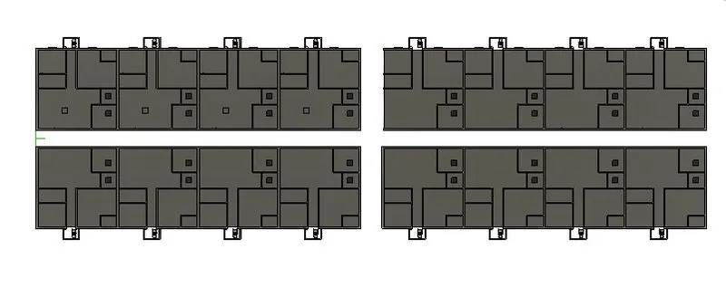
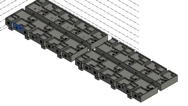
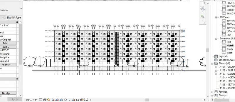
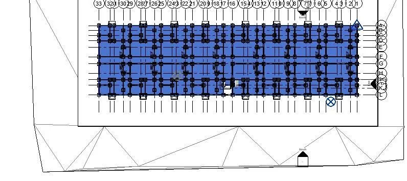
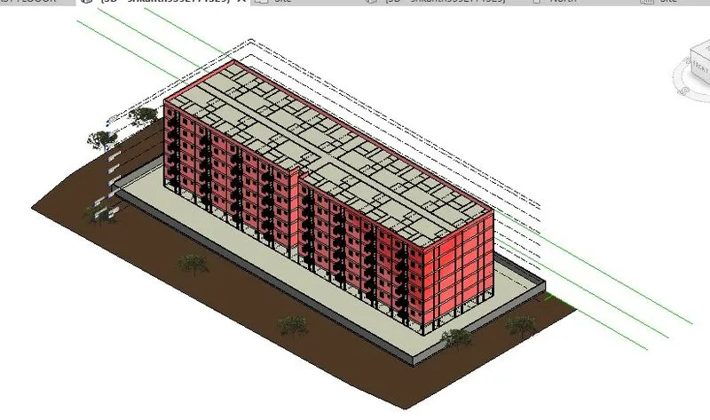
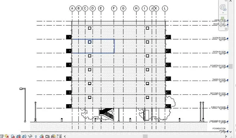
Result:I have created residential architectural model which comprise of walls,components .
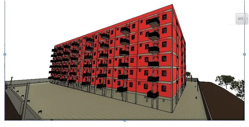
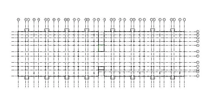
5.Aim: TO add the views like floor plans, elevations,sections in the sheets.
Software that i used-Revit
procedure
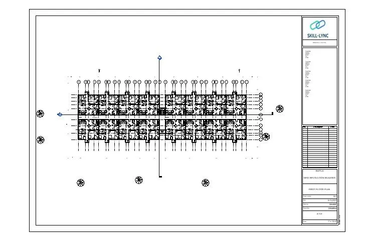
go to plan view select the architectural and structural views from the foundation to the roof levels.
crop the views by using crop region.
remove unnecssery portion(or) hide that elements.
sometimes we have to use scope box if the plan doesnot fit to the sheet.
by changing the scale we have to fit the views in the sheets.
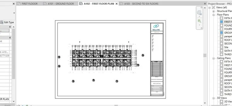
go to architectural model select the views and drag in to the sheets.
before placing the titleblock in the workset we need to fill the project information .
after then place the title block if you want to change the details then diuble click on the text.
i choose the A0 metric template.
the actual true north is 10 degree away from the project north.
i show the symbol for the detail information.
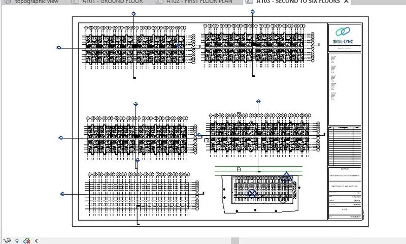
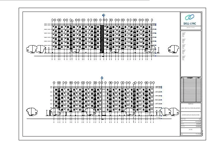
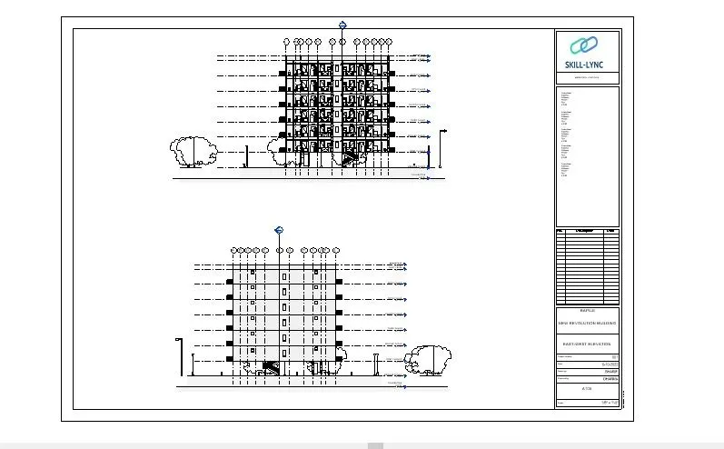
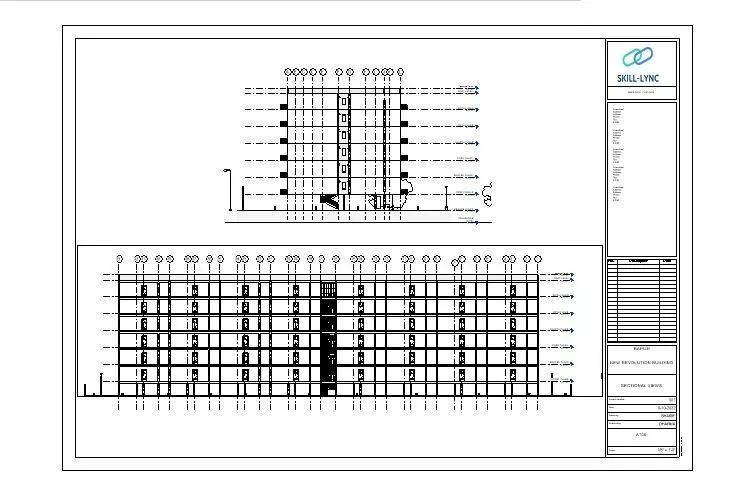
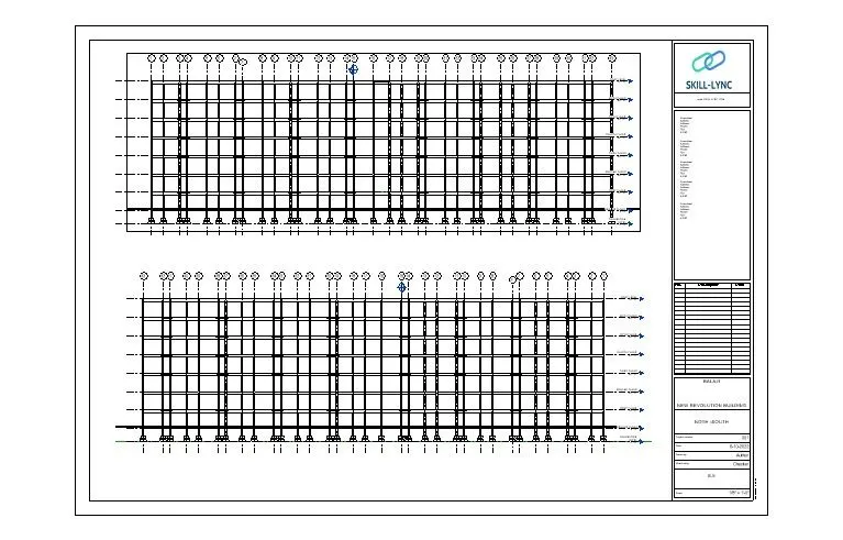
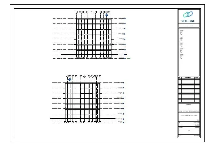
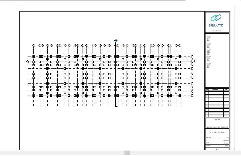
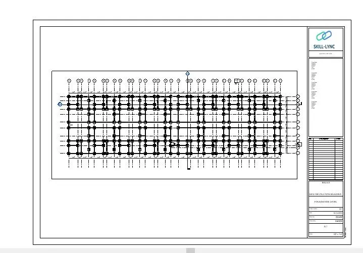
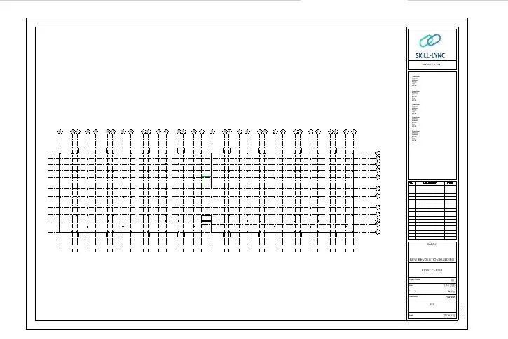
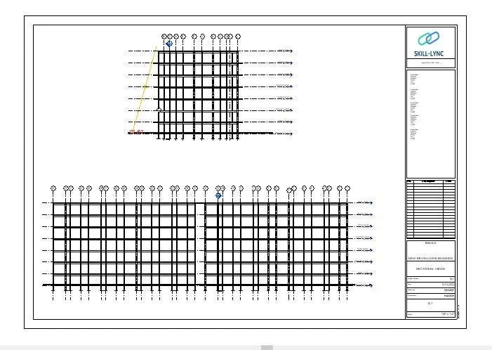
Result I have added the views like floor plans, elevations,sections in the sheets.
6.Aim: TO add the rendering architectural ,structural model images on the sheets
software that i used Rivet
procedure.
before rendering we need to take 3d view .
rendering only apply on the 3d views not for plan,elevation.
i have saved some 3d views which comprise different rooms,floors,topographic,structural.
go to view tab.
select the render which is above the presentation panel.
setting palette is open change the setting according to the site location.
adjust the exposure.
go to render in cloud select the all 3d view fix the aspects and submit it.
after few minutes check the render in gallery we can see the render images of the model.
take sheet which in the view tab.
edit the title block.
place the render views in the sheet we can crop that image by changing in the property palette.
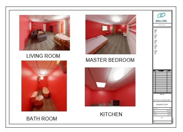
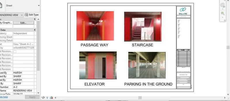
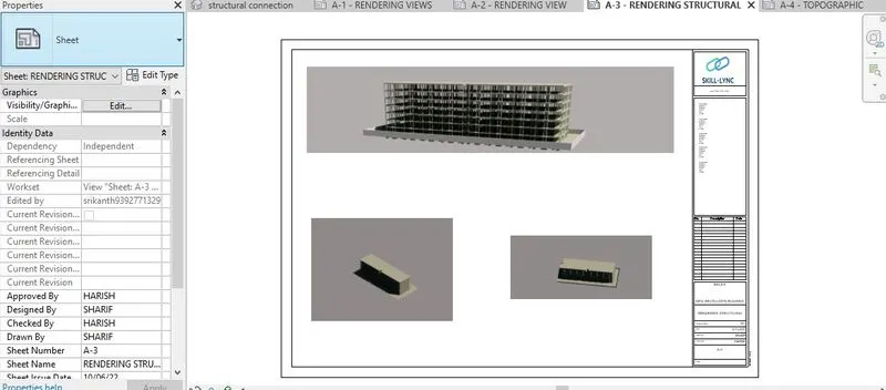
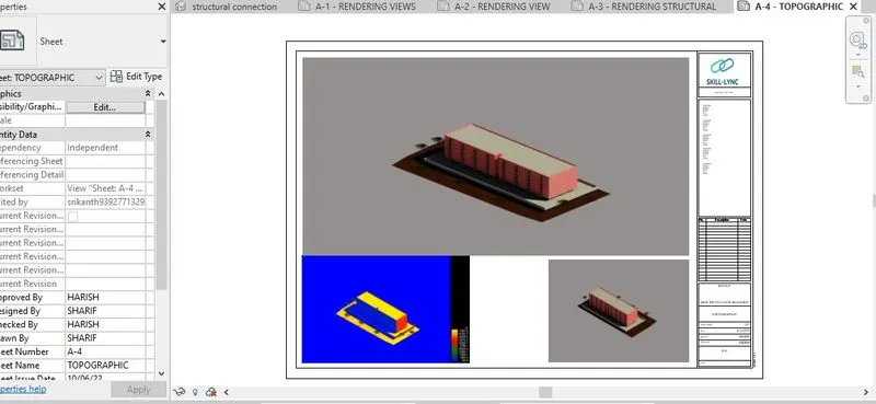
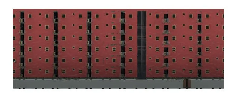
Result : I have added the rendering architectural ,structural model images on the sheets.
7.Aim: To print the drwaing sheets in the rivet.
software used - rivet
procedure
go to file tab
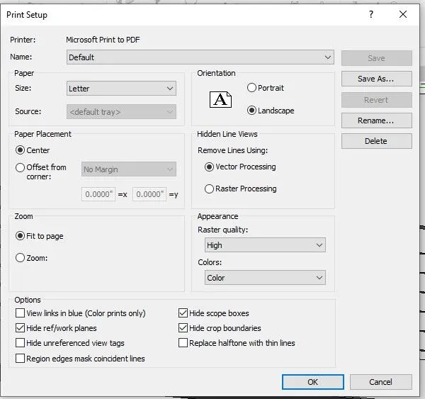
select the print option
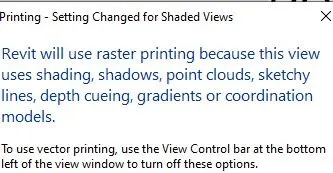
change the settings according to your ascpect.
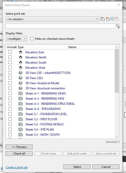
at bottom you can see the select views and sheets
select the all sheets and views we i have created for my modelling.
this is the lod 4 stage .
after detailed design we are going to prepare the drafting documention.
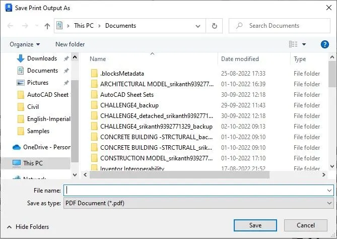
choose the relative(or) absolute file location path.
print it.
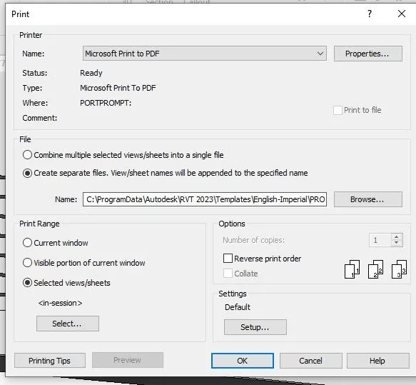
Result: i have printed my model drawing sheets in the rivet.