Creating a Floor plan, Footing detail and Isometric view using AutoCad
Creating a Floor plan, Footing detail and Isometric view using AutoCad
Aim : To sketch the floor plan,footing details and isometric view geometry
software i have used autocad
tools that i used
line
trim
fillet
offset
text
rectangle
move
copy
mirror
dimension
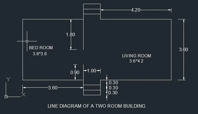
Floor plan of two room building
procedure:
- Draw the rectangle with rec coomand.
- specify the first corner point is (1,1)
- specify the second corner point is @ 7.8 , 3.6 units.
- take line command specify the first is (4,6,1)
- draw a line vertical with 0.9 units
- shift the direction to 0 degree draw a line with 1 unit
- shift the direction to 90 degree draw the line 0.9 units
- take the offset tools provide the space 0.3 on each step,
- take the mirror tool choose the midpoint as reference to place the replica of steps in the opposite direction.
- inital point of step is to project to 0.90 units in the 90 degree.
- in the meanwhile inital point of opposite step is to project to 0.90 units in the 270 degree.
- give the dimension to the plan
- annotate text is provided to the plan.
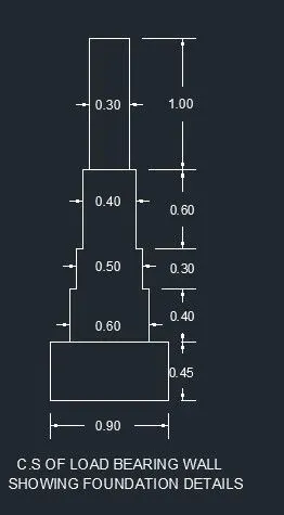
c/s of load bearing wall showing foundation wall.
procedure
- draw the rectangle with dimension 0.9 x 0.45 units
- take copy tool project it in to vertical direction with zero offset.
- surpess the each footings to thier specified dimension by dragging grips.
- for successive two footings only applicable .
- in the forth footing is extend in the verticasl direction and type 0.60 units press enter.
- the top one which is column have to elongate to the vertical direction till up to 1 unit.
- take trim tool remove the unwanted portions.
- give dimension to each footing layer.
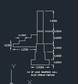
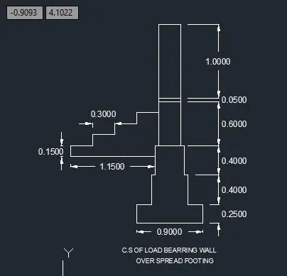
c/s of load bearing wallover spread footing
procedure
- Draw the rectangle with dimension 0.9 x 0.25 units
- take copy tool project it in to vertical direction with zero offset.
- drag the grips unil to get the desired dimensions.
- same procedure is repeat to the second footing and third footing.
- draw the offset line with distance of 0.6 units to the top.
- draw the column bu using line,offset,extend tools.
- draw the steps by using offset,line, trim.
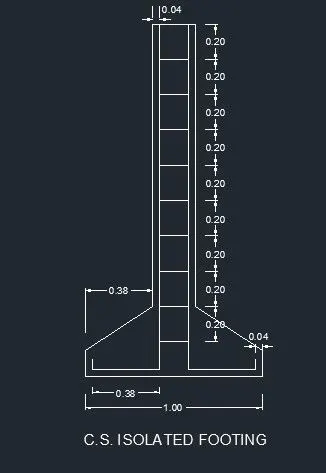
c/s isolated footing
procedure
- draw the line 0.5 units in the 0 degree direction
- at the last end draw a line with 0.15 units in 90 degree direction
- draw aline starting specific point is (@-0.45,0.38 from the last end of o deree line
- draw a line with 1.6 unit in the 9o degree direction.
- join the top end points like @-0.45,0.38 and @0,0.15 inclined line is formed.
- shift the direction to 180 degree draw a line with 0.04 unit
- shift the direction to 270 degree draw aline 1.96 units
- shift the direction to 0 degree draw a line 0.36 units
- shift the direction to 90 degree draw a line 0.06
- in the top 180 degree line is extend to 0.08 unit
- take mirror tools select all geometry reflect the replica to the other side.
- take an offset tool with the distance as 0.20 unit and select the top 180 degree line.
- project to the downside .
- up to the 8 successive action takes place.
- give the dimension to the sketch.
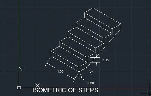
Isometric of steps:
procedure:
- set the isoplane on .
- shift the isoplane to right,left,top by typing F5 button.
- draw the line in 90 degree direction of 15 unit with respect to the inital end point of 0.30 unit.
- same procedure is repeated up to landing.
- shift to isoplane right draw a line with 1 unit to the 150 degree.
- take the copy tool select the right portion entity geomentry.
- place to the left side by click the left end side line.
- connect the each opposite ends.
- select the isoplane right draw a line 0.30 unit.
- select the point on the top right end draw a line 0.15 to 270 degree direction.
- connect the two end of 0.30 unit and 0.15 units and forms the inclined line.
- provide the dimensions to the single step.
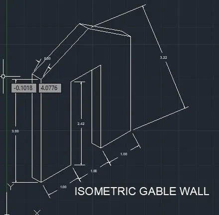
ISOMETRIC GABLE WALL
PROCEDURE
- fix the isoplane in the right side draw a line 3 unit.
- remove the middle portion 1 unit by placing points on it use trim tool to remove it.
- draw the 90 degree line on the each end .
- first line intial end with distance 3 unit.
- first line final end with distance 2.42 unit.
- same procedure is repeats to the another line but reverese end position.
- provide the wall thickness 0.30 units by using offset.
- join the wall thickness width line.
- specify the first point is @1.56,3.22 from the strat line .
- inclined lines are form whilie joining to the point.
- provide wall thickness by using offset.
- provide the dimension to the geometry
Result sketching the floor plan,footing details and isometric view geometry are completed
Floor plan of two room building
c/s of load bearing wall showing foundation wall.
c/s of load bearing wallover spread footing
c/s isolated footing
Isometric of steps:
ISOMETRIC GABLE WALL