Creation of geometries by Coordinate system methods using AutoCad
Create the geometries from P1 to P2 using all the coordinates system methods. You need to use the Line tool to create the geometries. Where required you need to use the circle tool.
Please read the drawings and find out the missing dimensions before working on the sketches.
Aim: To create geometries from P1 to P2 using all the coordinates system methods and Draw the profile and the trusses using any coordinate system methods.
commands i used
Line
circle
Text
Dimensions
Method i adopted
1.Absolute coordination method
2.Relative rectangular coordination method
3. Relative polar coordination method
4. direct value enter method
1.Absolute coordination method procedure:
Take a line command (L+Enter)
specify first point (x,y)
specify next point (x,y)
specify next point(x,y) or undo
Absolute coordinate for p1 figure
- Take aline command
- specify first point(2,1)
- specify next point(8,1)
- specify next point(8,2)
- specify next point (3,2)
- specify next point(3,6)
- specify next point(8,6)
- specify next point(8,7)
- specify next point(2,7)
- specify next point(2,1) or c enter
Relative polar coordinate method procedure: for p1
- take a line command
- specify first point (2,1)
- specify next point(@6<0 degree)
- specify next point(@1<90 degree)
- specify next point(@5<180 degree)
- specify next point(@4<90 degree)
- specify next point(@5<0 degree)
- specify next point(@1<90 degree)
- specify next point(@6<180 degree)
- specify next point(@6<270 degree) or close or (2,1)
Relative rectangular coordination method procedure p1figure
- Take a line command
- specify first point (2,1)
- specify next point (@6,0)
- specify next point (@0,1)
- specify next point (@-5,0)
- specify next point (@0,4)
- specify next point (@5,0)
- specify next point (@0,1)
- specify next point (@-6,0)
- specify next point (@0,-6) 0r (2,1) 0r close
Direct value entry method
- Take a line command
- specify first point (2,1)
- specify next point 6 enter (cursor right side)
- specify next point 1enter (cursor upside side)
- specify next point 5 enter (cursor left side)
- specify next point 4enter (cursor upside side)
- specify next point 5enter (cursor right side)
- specify next point 1enter (cursor upside side)
- specify next point 6enter (cursor left side)
- specify next point 6 enter (cursor downside side)
The same procedure is repeated to the P2 figure.
Result:
I completed the all geometric models and civil related models using the coordinates system methods in autocad software.
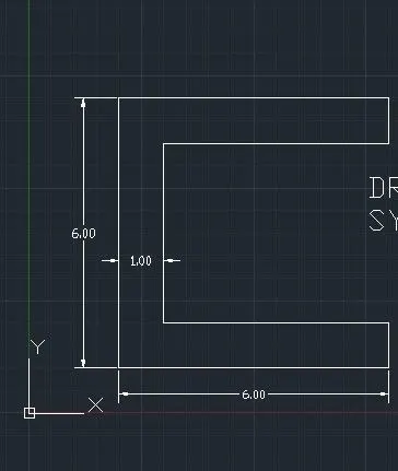
Absolute coordination system P1
Relative coordination system p1
Relative polar coordination system
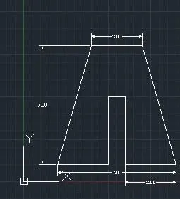
Absolute coordination system
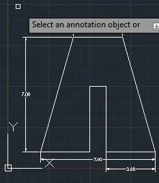
Relative rectangular coordination system
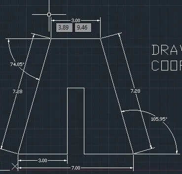
Relative polar coordination system
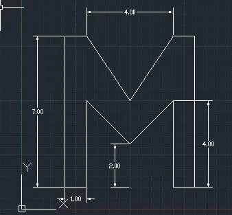
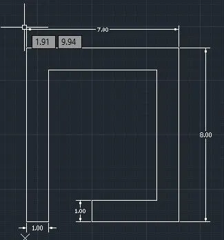
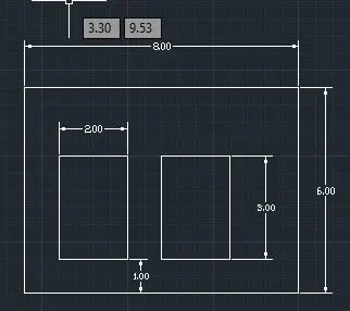
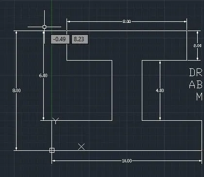
BY USING DIFFERENT METHODS I DRA THE BELOW MODELS
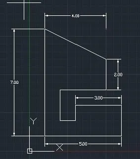
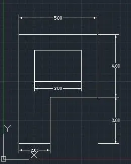
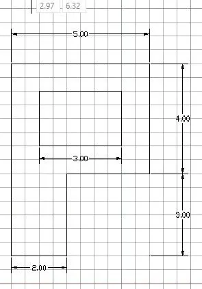
layout of the above model
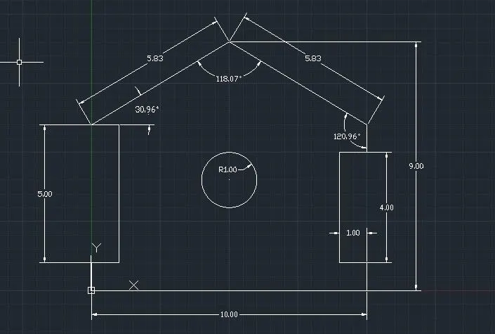
PROFILE WOOD
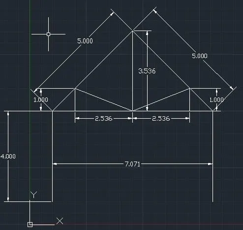
QUEEN POST TRUSS
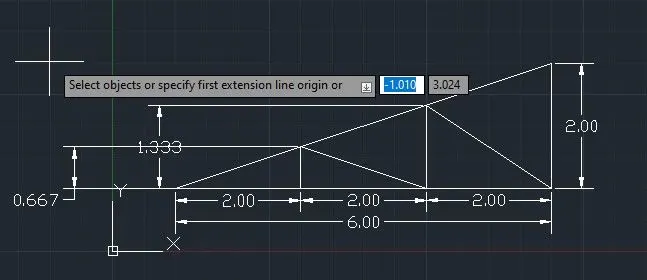
MONO PITCH