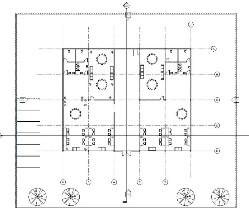
Creating Architectural and Structural model with 3D rendering using REVIT
1)Select the type of structure you want to build from one of the three below:
- Multi-Unit Residential Apartment
- Office Buildings
- School
Selected Office building
2)Assume reasonable assumptions for geographic and location details for your project modelling. Based on assumptions and type of structure selected identify the modelling requirements from NBC
The building comes under group E
The open space around the building less than 4.5 m
FAR value for type 2 construction is 2.9
The size of the plot is 47X40
The individual floor area 743 m^2
The FAR value is 1.18 (less than permissible,hence ok)
The width of the road abutting the building is taken as 9m
AIM
Using the structural model, include the following components based on the type of structure selected
- Foundation – Isolated / Wall/Matt Foundation
- Columns
- Beams Connected to Columns
- Roof Framing/ Truss
- Floor / Decks
- Floor Openings for Elevators and Stairs
INTRODUCTION
Autodesk Revit is a BIM(Building Information Modelling) software civil engineers, architects, mechanical,electrical,plumbing(MEP)engineers
Here we are using Manage tab in Revit
PROCEDURE
Step 1:Open Revit software
Select new option
Open structural template created
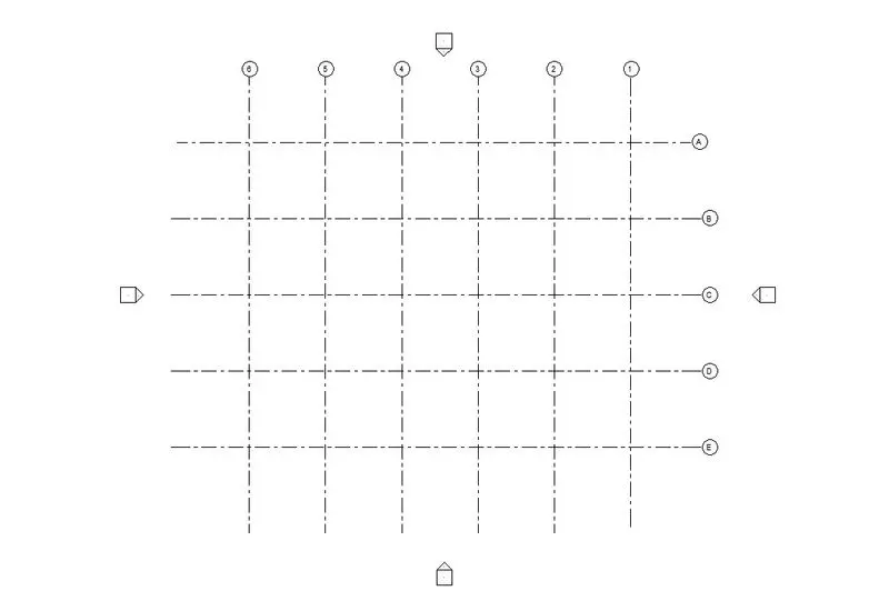
Step 2:Select structure tab
Select foundation
Select ‘At Grids’ option
Select the grids
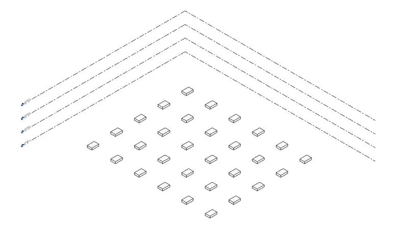
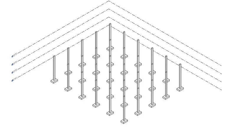
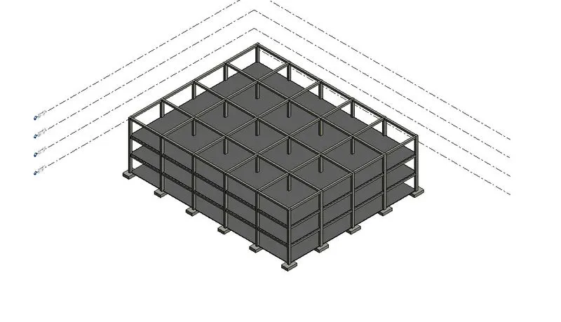
Step 3:Select structure tab
Select column
Select ‘At Grids’ option
Select the grids
Extend the column to top level
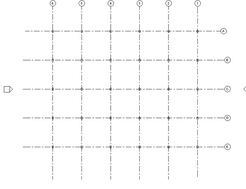
Step 4:Select structure tab
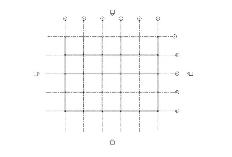
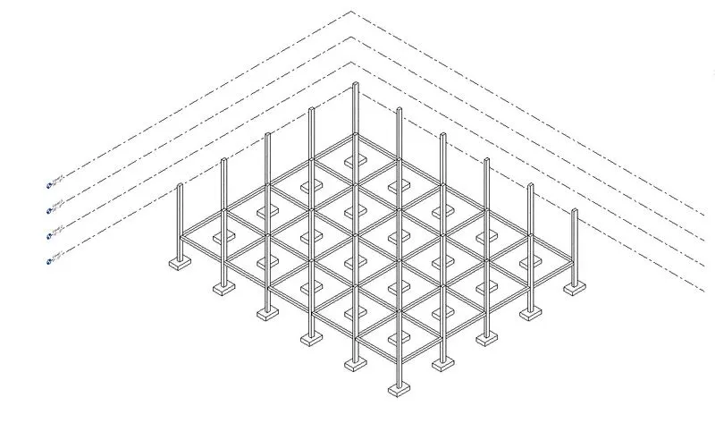
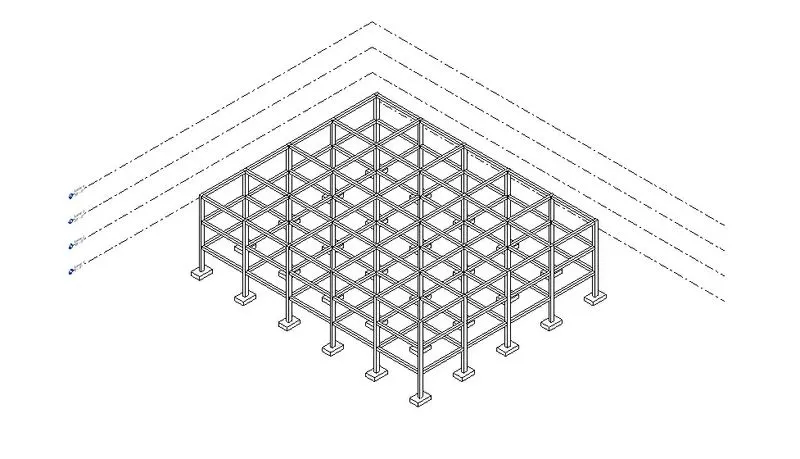
Select beam
Select ‘At Grids’ option
Select the grids
Copy the beam to other two level
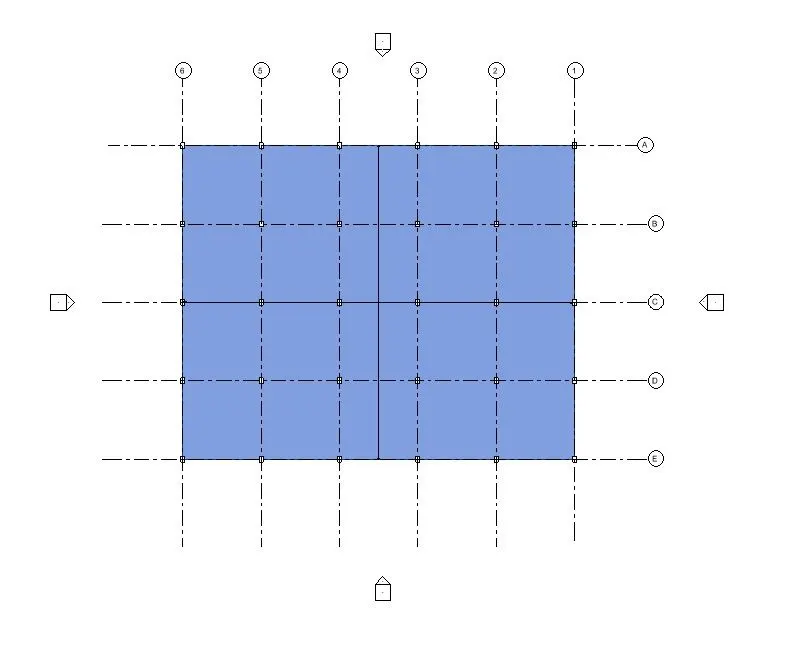
Step 5:Select the floor option
Set the plan to floor level
Draw the boundary
Step 6:Select the roof option
Set the plan to roof level
Draw the boundary
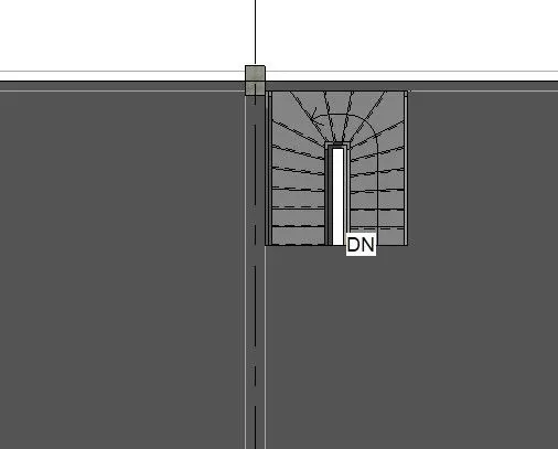
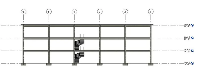
Step 6:Select staircase option and draw the staircase at level 1
Connect the stair two other levels
Select shaft option cut the place for staircase
RESULT
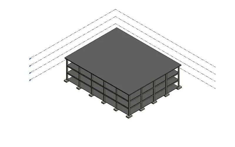
AIM
Using the architectural model, include the following components based on the type of structure selected
- Wall Layout with appropriate material and finishing
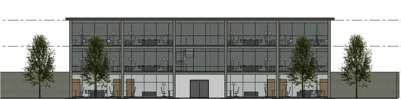
- Exterior façade with fancy finish
- Interior partition walls to size rooms
- Components to add details to a room ( Desk, Chair, Lighting, Plumbing fixtures)
- Add components such as stairs Elevators
- Have at-least one side of the building with curtain walls and glass panels
- Include interior and exterior lighting fixtures
- Place proper topographic components from outside ( Trees, Parking, Plants) to add details to the model
INTRODUCTION
Autodesk Revit is a BIM(Building Information Modelling) software civil engineers, architects, mechanical,electrical,plumbing(MEP)engineers
Here we are using Manage tab in Revit
PROCEDURE
Step 1:Open architecture template
Select link Revit
Link the structural drawing
Step 2:Draw external walls through the boundary
Draw internal partition walls
Provide doors
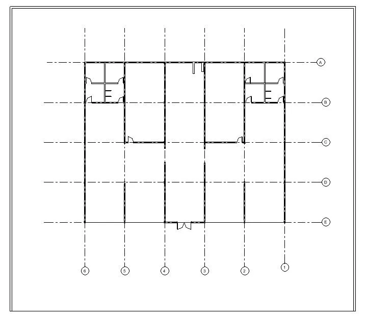
Step 3:Add furniture and lightings
Step 4:Add annotations
Select massing and site tab
Select site components
Provide trees and parking slots
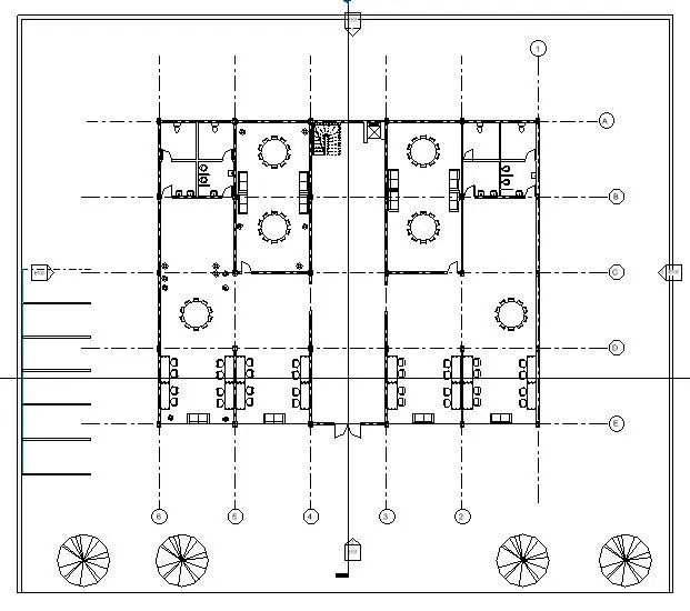
Step 5:Provide curtain glass wall to other front wall
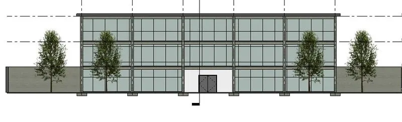
RESULT
AIM
Provide a set of drawings in an architectural and structural model to list the following details with categories and appropriate sheet templates included
- Floor Plans with Annotations
- Elevations
- Sections
INTRODUCTION
Autodesk Revit is a BIM(Building Information Modelling) software civil engineers, architects, mechanical,electrical,plumbing(MEP)engineers
Here we are using Manage tab in Revit
PROCEDURE
Step 1:Select view tab
Select sheet option
Step 2:Add drawings to the sheet
Add appropriate name to the sheets
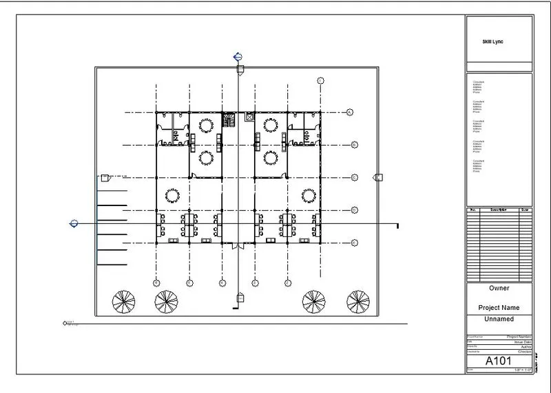
Step 3:Provide name A101
Select ground floor plan
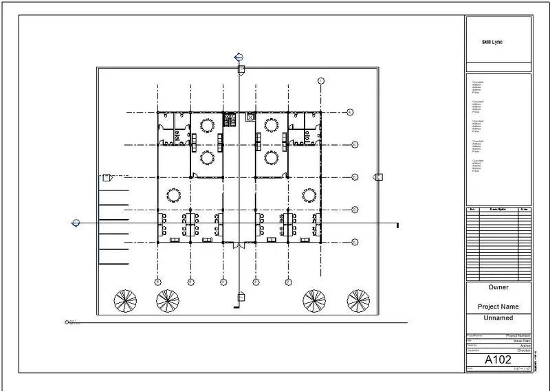
Step 4:Provide name A102
Select first floor plan
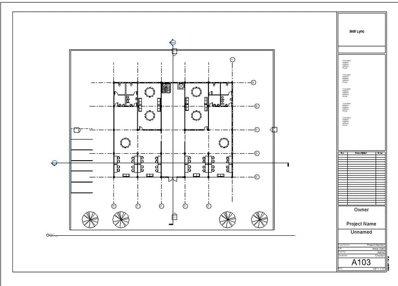
Step 5:Provide name A103
Select second floor plan
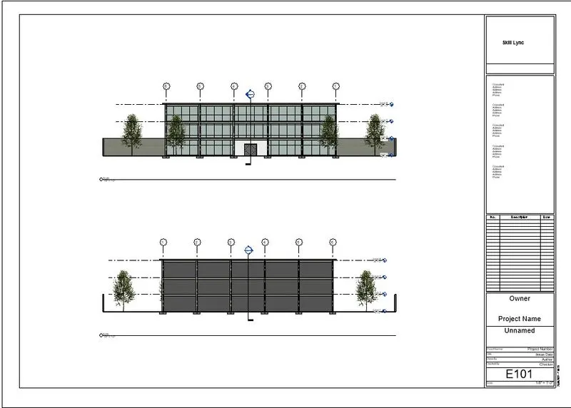
Step 6:Provide name E101
Select North and South Elevation
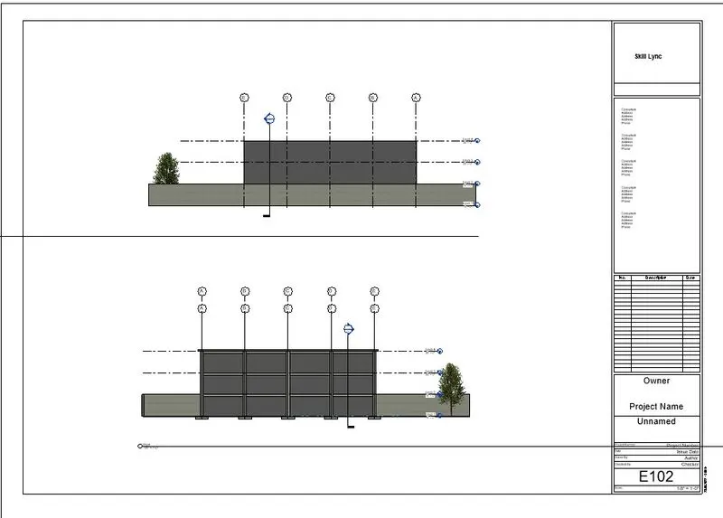
Step 7:Provide name E102
Select West and East Elevation
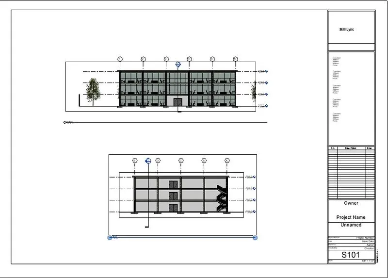
Step 8:Provide name S101
Select Sections
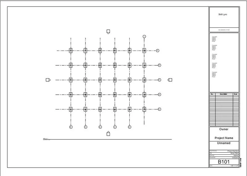
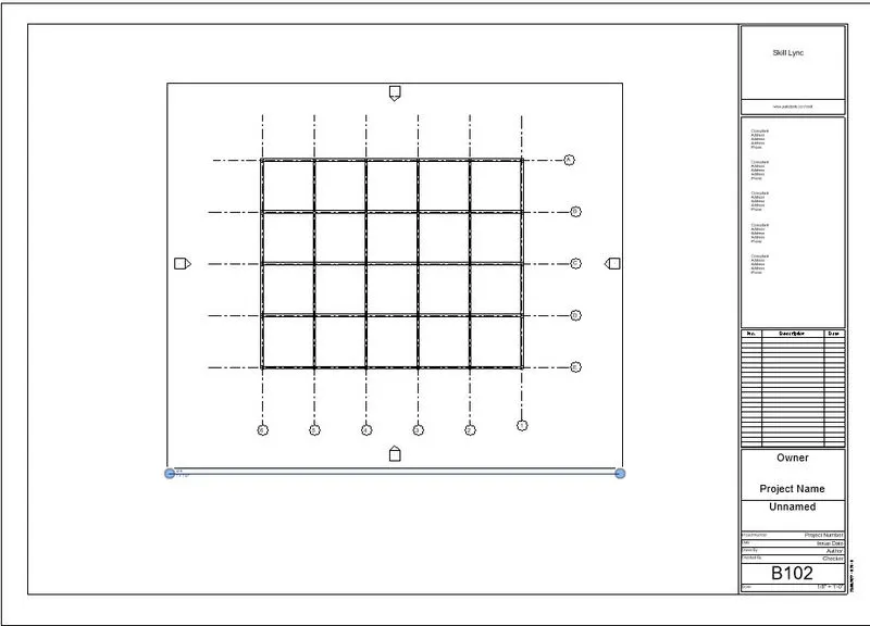
Step 9:Provide name B101
Select Footing drawing
Step 10:Provide name B101
Select structural drawing
RESULT
The drawings are set into sheets
AIM
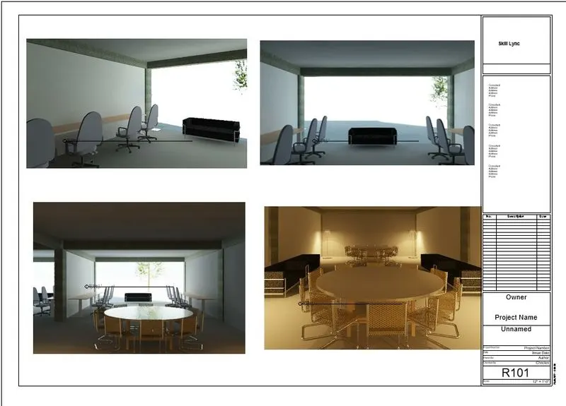
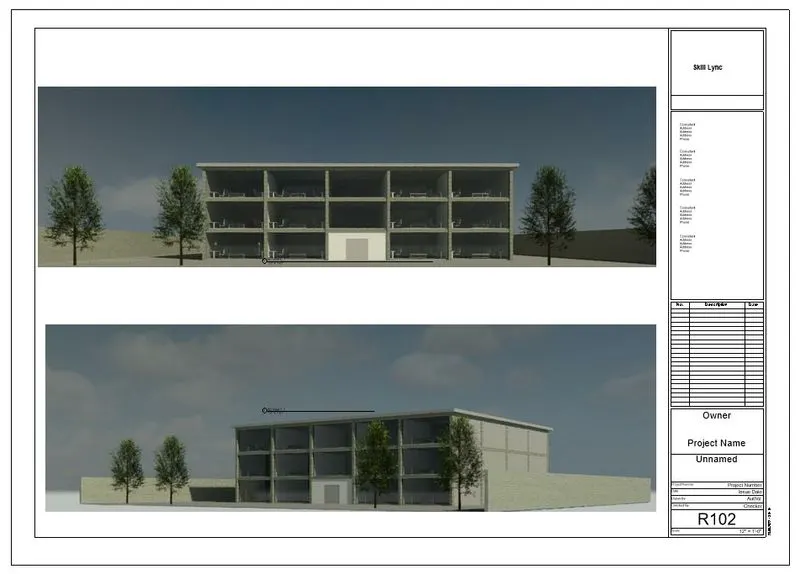
Using the Rendering settings, Render images of the 3D model produced and include the rendered images to the drawing sheets
- Rendering from interior rooms
- Rendering from out showing topographic features
- Rendering through structural framing
INTRODUCTION
Autodesk Revit is a BIM(Building Information Modelling) software civil engineers, architects, mechanical,electrical,plumbing(MEP)engineers
Here we are using Manage tab in Revit
PROCEDURE
Step 1:Select camera tab
Set views
Step 2:Set different views
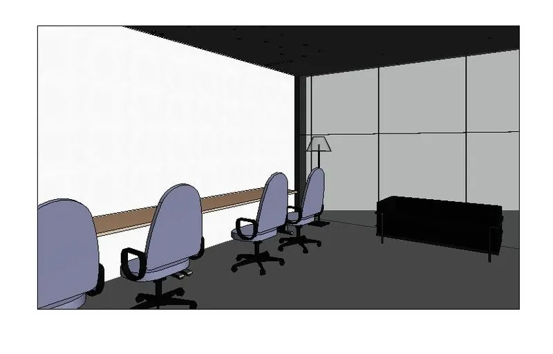
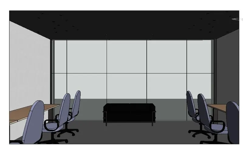
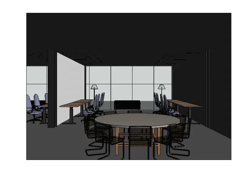
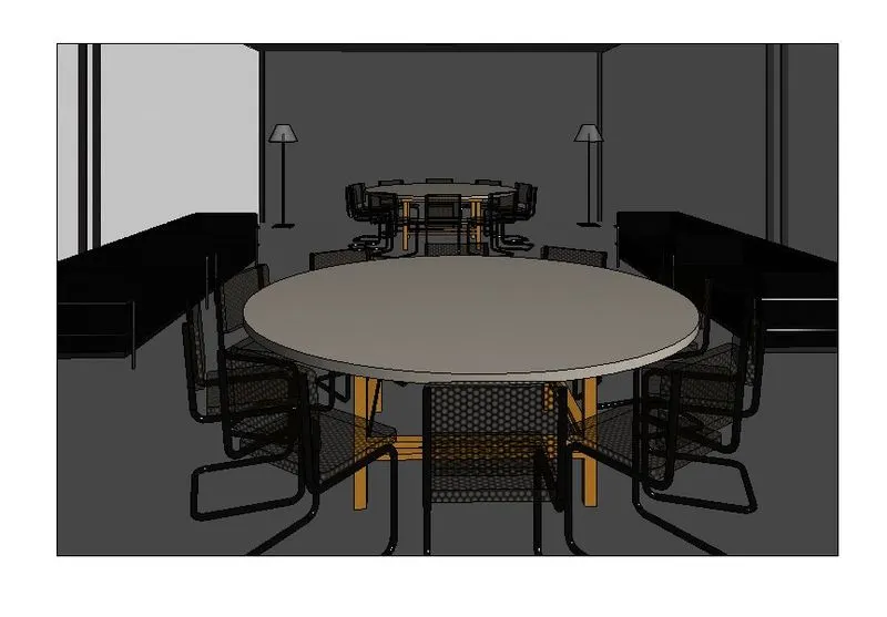
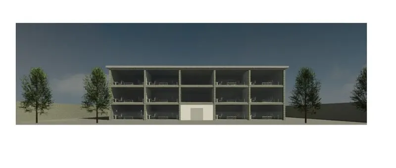
Step 3:After setting the view
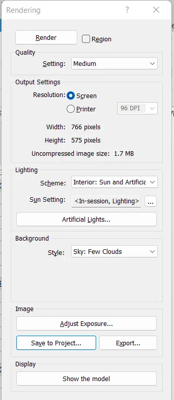
Enter RR command
Select suitable parameters
Render the image
RESULT
AIM
Print the set of drawing sheets created and submit the drawings from the architecture and structure model
INTRODUCTION
Autodesk Revit is a BIM(Building Information Modelling) software civil engineers, architects, mechanical,electrical,plumbing(MEP)engineers
Here we are using Manage tab in Revit
PROCEDURE
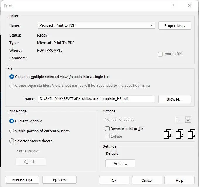
Step 1:After setting the sheet
Enter ctrl + P
Step 2:Provide data
Print the sheets
RESULT