Creating Architectural and Structural model with 3D rendering using REVIT
1) Select the type of structure you want to build from one of the three below:
a. Multi-Unit Residential Apartment
b. Office Buildings
c. School
Office building is my choise for this project.
2) Assume reasonable assumptions for geographic and location details for your project modeling. Based on assumptions and type of structure selected identify the modeling requirements from NBC.
The project is constructed in coimbatore.
Modelling requirements from NBC:
- The open space around the building shall not be less than 4.5m.
- Considering the type of construction as type 2 construction, the FAR value for the business building shall be taken as 2.9. The plot size is taken as 50mx60m i.e, 3000m^2 and individual floor area is 2091m^2. Hence, FAR value obtained is 2.8 which is within the prescribed limits as per NBC.
- The width of the road abutting the building is taken as 30'.
- The maximum height of the building shall not exceed 1.5 times the width of road abutting plus the front open space.
- The building consists of 4 floors and each floor having a height of 3m. The entire floor height is 12m which is within the prescribed limits as per NBC.
3) Using the structural model, include the following components based on the type of structure selected
a. Foundation – Isolated / Wall/Matt Foundation
b. Columns
c. Beams Connected to Columns
d. Roof Framing/ Truss
e. Floor / Decks
f. Floor Openings for Elevators and Stairs
Aim:
To create the following components based on the type of structure selected.
a. Foundation – Isolated / Wall/Matt Foundation
b. Columns
c. Beams Connected to Columns
d. Roof Framing/ Truss
e. Floor / Decks
f. Floor Openings for Elevators and Stairs
Introduction:
The structural model is the 3D representation of the elements like footings, clomuns, beams, floors. This will created in the structural template for the analysis process.
Procedure:
- Open Revit software. Open new project with 'structural template'
- Save the project with the name of 'Project 1 structural'
- Collaborate the project to make it as a central model.
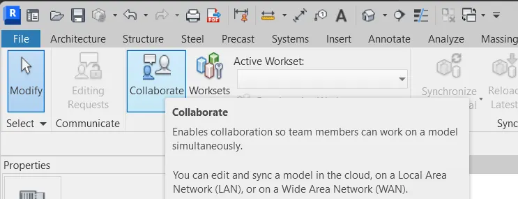

- Again save the project this time the project will be saved as a 'central model'
- Create the grids in the langitudinal and transverse direction.
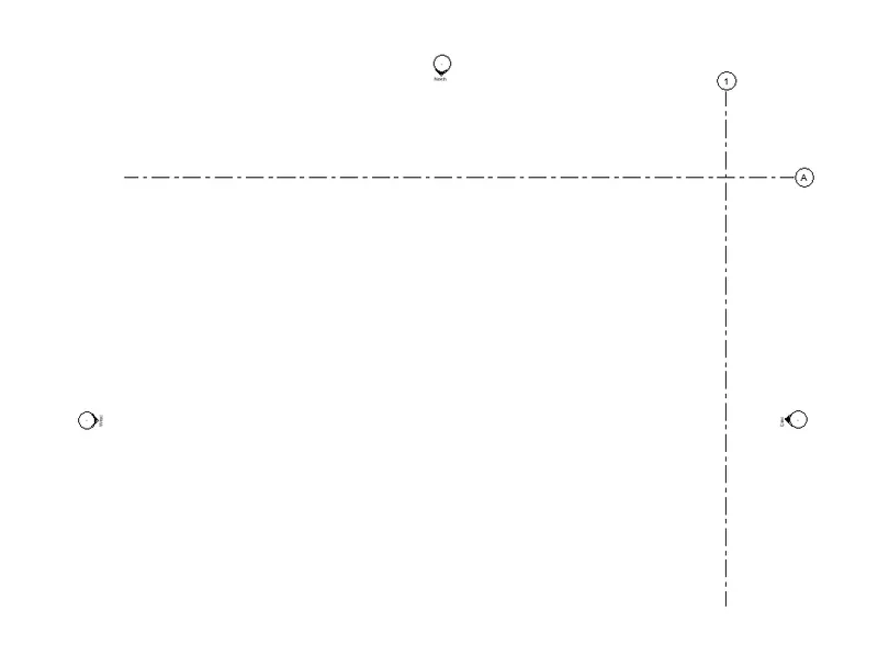
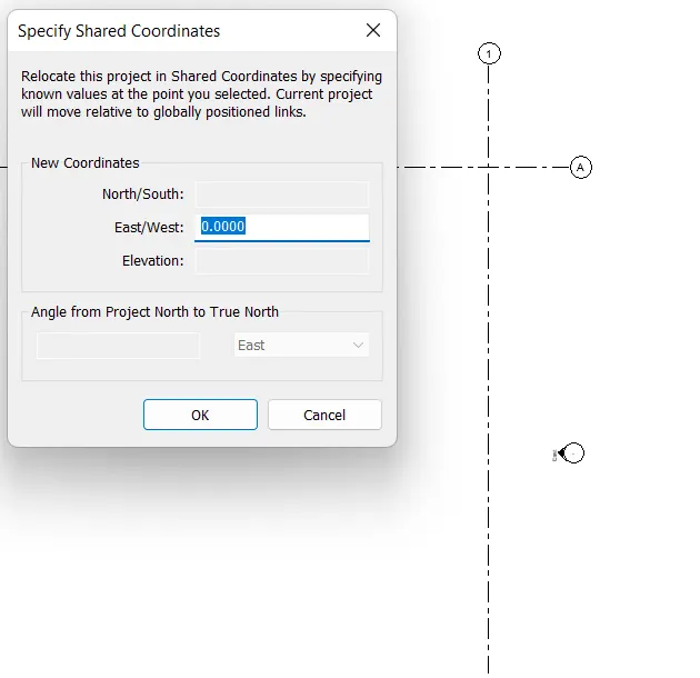
- Specify Coordinate to the grids created.
- Specify the langitudinal grid East/West coordinates as 0
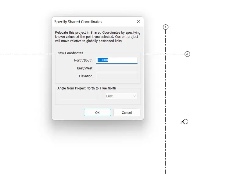
- Specify the transverse grid North/South coordinates as 0
- Specify the project base point.
- Open visuality graphics settings.
- Select the project base point under the site category.
- Move the project base point to the intersection of the two grids.
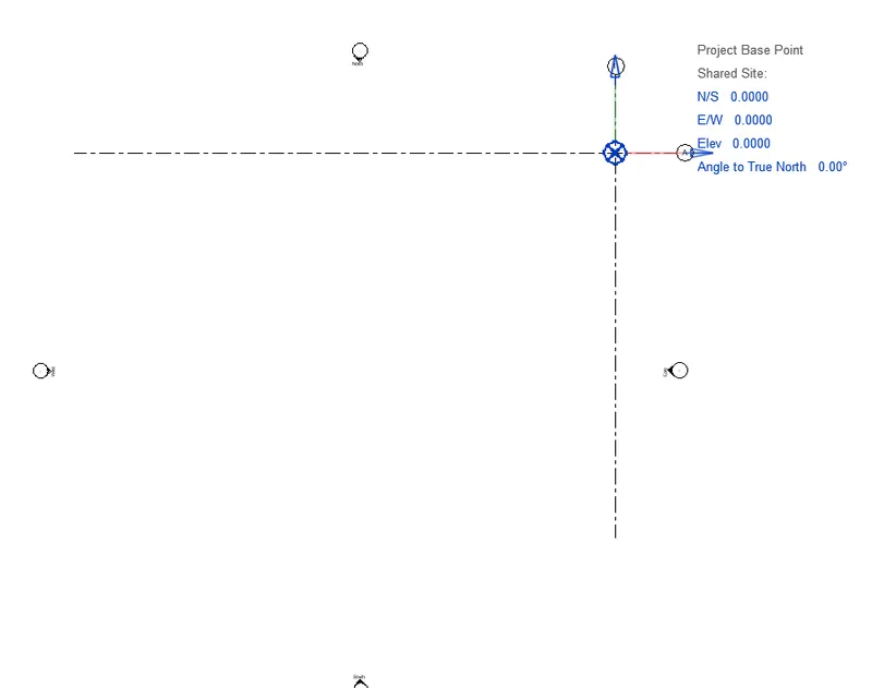
- Create a conceptual sketch of layout using model line.
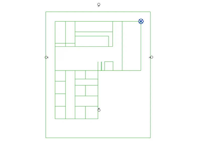
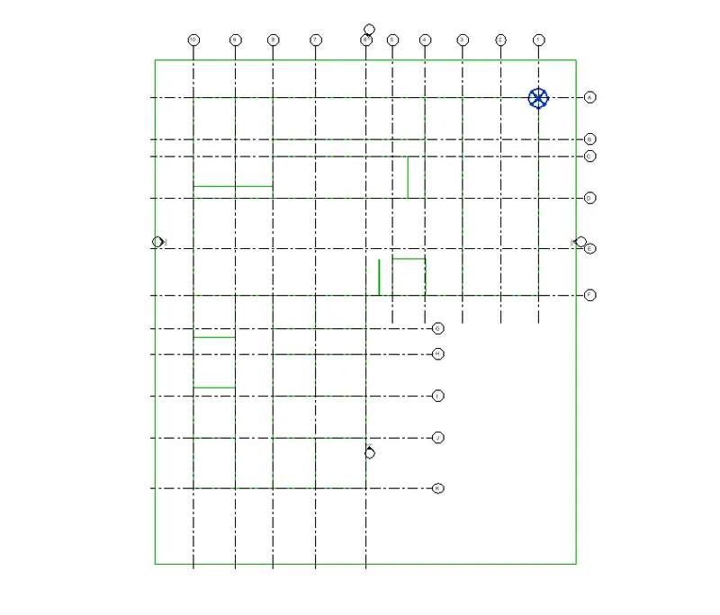
- Create longitudinal and transverse grids with respecgt to the layout created.
- Open structure tab select grids under dattum pannel.
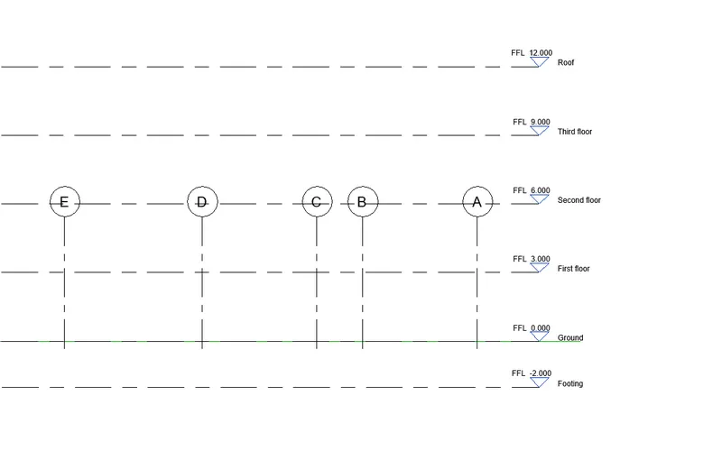
- Create respective levels of the project.
- Open east elevation.
- Select levels and create the levels.
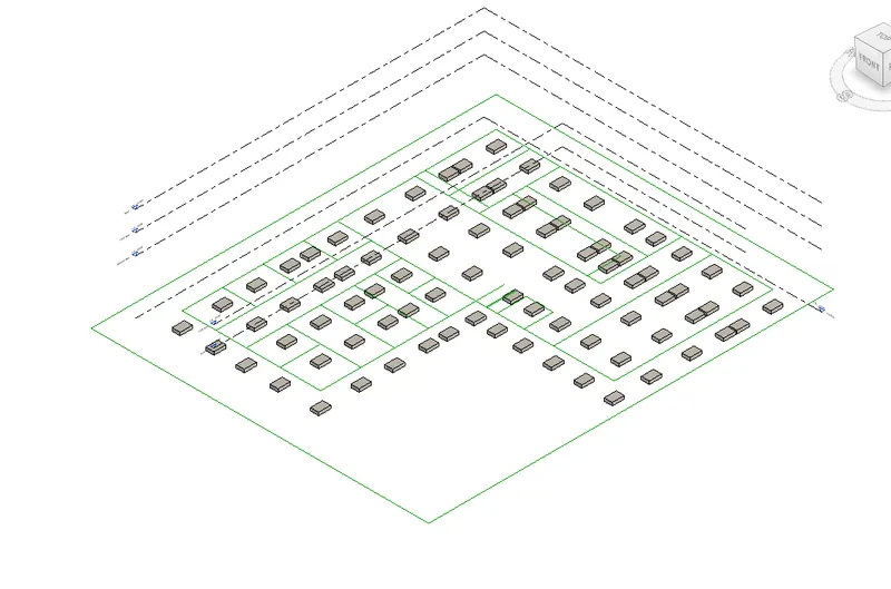
- Create isolated footing at the grids intersection.
- Switch to footing plan.
- Select isolated footing under structural tab.
- Select all the grids and click ok.
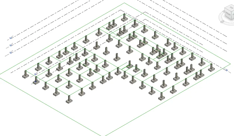
- Creation of columns.
- Select column under structure tab.
- Select the column type and size.
- Select all grids and click ok.
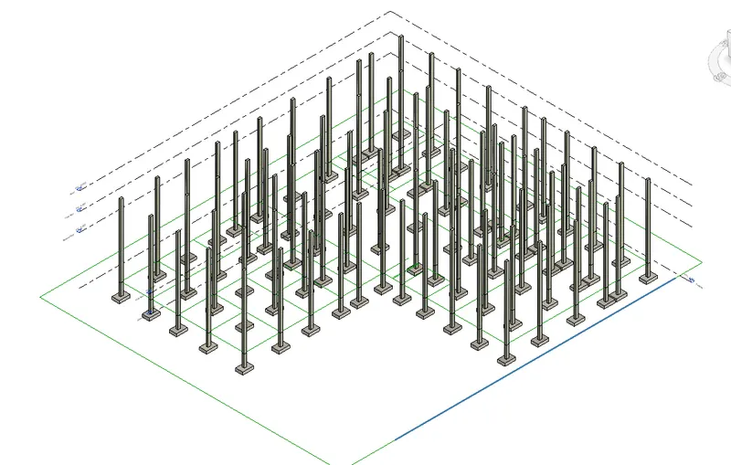
- Create columns at the ground floor.
- Select columns under structural tab.
- Set the base point at ground floor and top point at roof.
- Select all the grids and click ok.
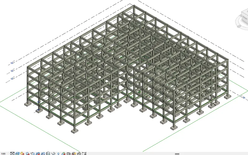
- Creation of beams.
- Selecty beams under structural tab.
- Select all the grids and place it at the footing level.
- Copy the beams in the footing level and paste it to the Groud to Roof level.
- Create Floors in the each level.
- First create floor in the ground level.
- Select floor under the structural tab.
- Select line tool to create the boundary of the floor.
- Copy the floor.
- Paste it to the first to roof level.
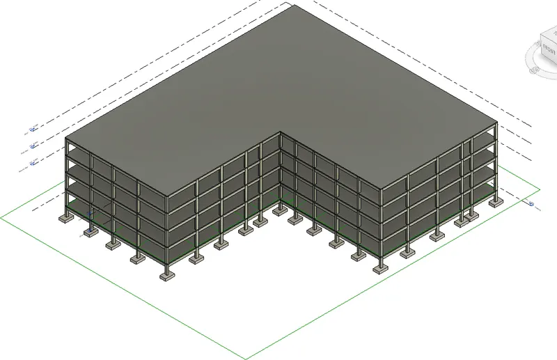
- Create Floor openings for stairs and elevators.
- Select shaft under the structural tab.
- Select line option.
- Create boundary of the shaft opening.
- Set the top constraint as roof.
- Click ok. The shaft/ floor opening is created.
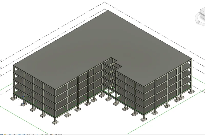
Result:
The components based on the type of structure seleted is created.
Foundation
Column
Beams
Floors
Openings for stair and elevators
4) Using the architectural model, include the following components based on the type of structure selected
a. Wall Layout with appropriate material and finishing
b. Exterior façade with fancy finish
c. Interior partition walls to size rooms
d. Components to add details to a room ( Desk, Chair, Lighting, Plumbing fixtures)
e. Add components such as stairs Elevators
f. Have at-least one side of the building with curtain walls and glass panels
g. Include interior and exterior lighting fixtures
h. Place proper topographic components from outside ( Trees, Parking, Plants) to add details to the model
Aim:
To include the following compomnents to the office building.
a. Wall Layout with appropriate material and finishing
b. Exterior façade with fancy finish
c. Interior partition walls to size rooms
d. Components to add details to a room ( Desk, Chair, Lighting, Plumbing fixtures)
e. Add components such as stairs Elevators
f. Have at-least one side of the building with curtain walls and glass panels
g. Include interior and exterior lighting fixtures
h. Place proper topographic components from outside ( Trees, Parking, Plants) to add details to the model
Introduction:
Architectural components are used provide the exterior and interior walls and components like desk, chair, lightings, plumbing fixtures etc...
Procedure:
- Open new project in the architectural template.
- Save the project.
- Use collaborate option to make the project as a central model.
- Create the grids in transverse and longitudinal direction.
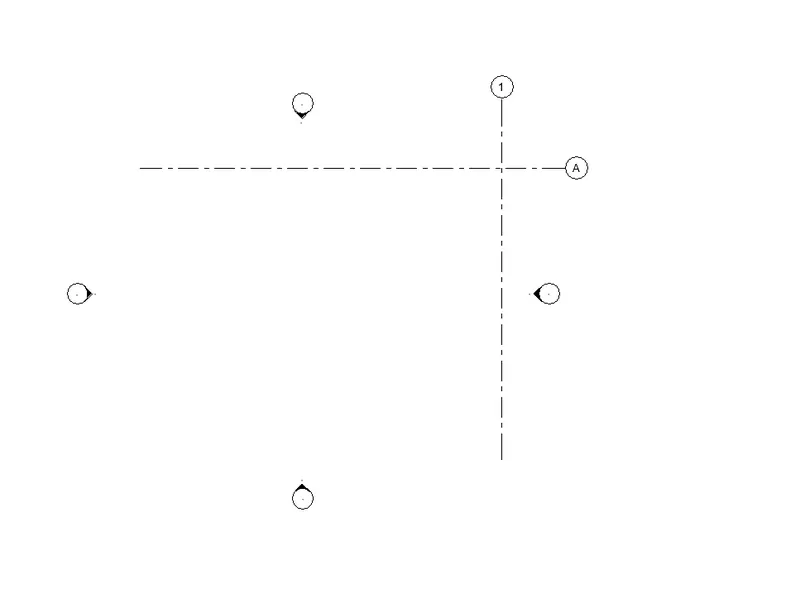
- Specify the coordinates, for tarnsverse grid East/West is 0 and longitudinal direction North/South is 0.
- set the project base point to the intersection point of the grids.
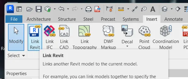
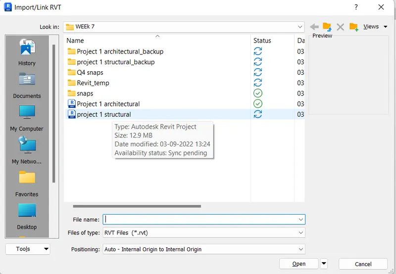
- Link the structural model to the architectural template.
- Select 'Revit link' under the insert tab.
- Select the structural model to link into this project.
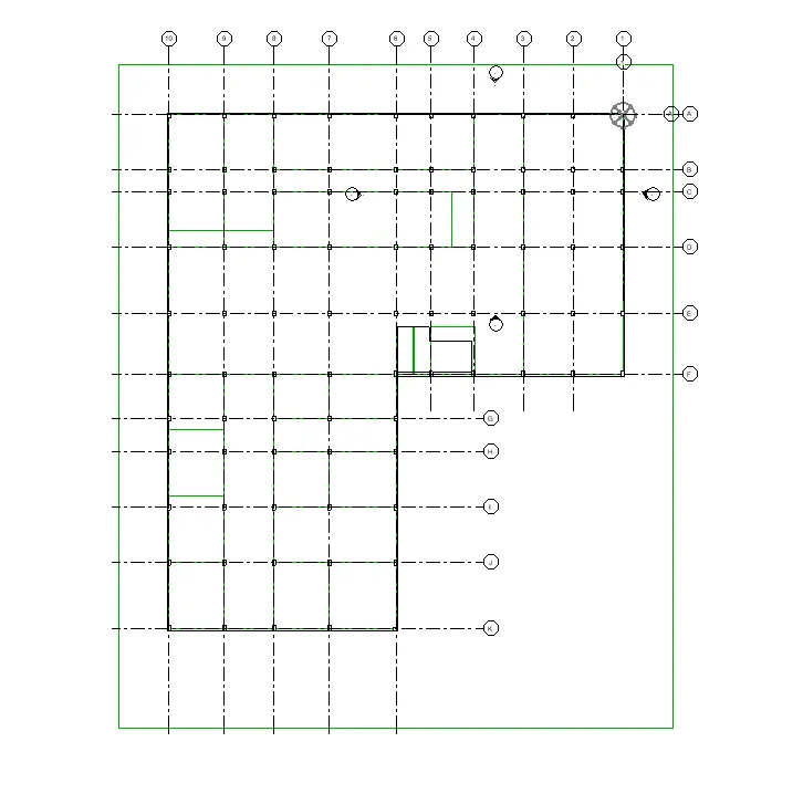
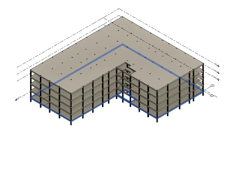
- Use copy monitor tool copy the structural elements into the host model.
- Select copy monitor under collaborate tab.
- Select the linked model.
- Select copy and multiple.
- Select the structures and click finish.
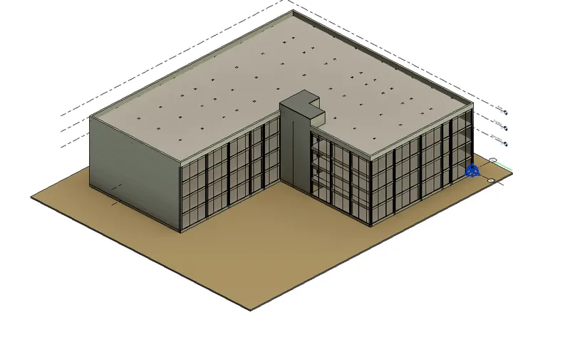
- Create wall layout.
- Select wall under architecture tab.
- Select generic 300 concrete wall.
- Arround the sides of the building.
- The front side of the building is covered with curtain wall.
- Create interior partition walls to size rooms.
- Select walls under architecture tab.
- Select interior wall from the properties browser.
- Start creating walls.
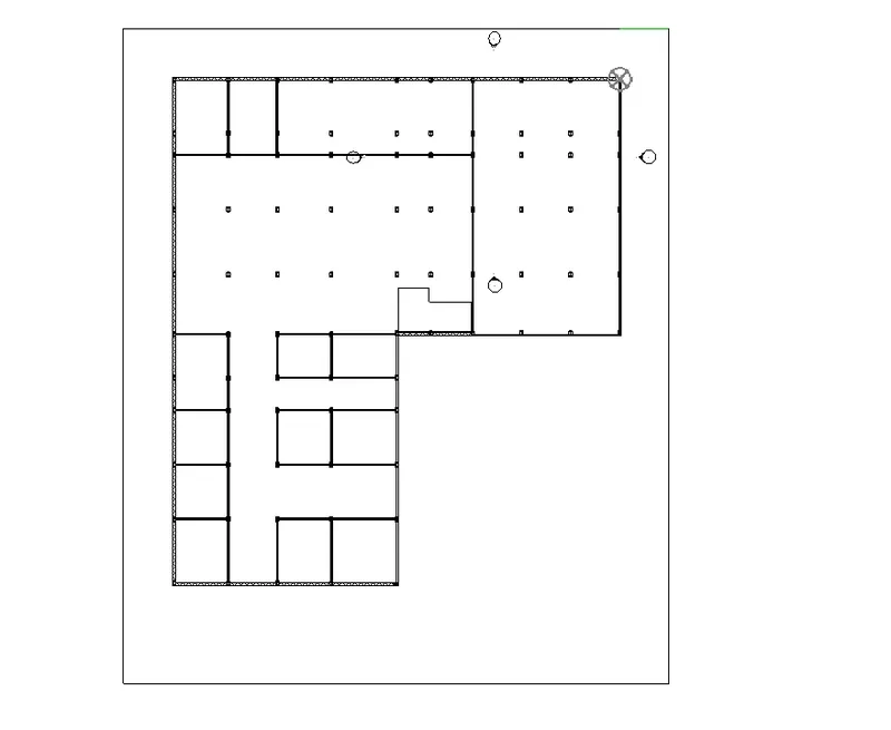
- Select the interior walls and copy it to the clipboard.
- Paset the copied walls to assigned selected views such as first floor, second floor, third floor.
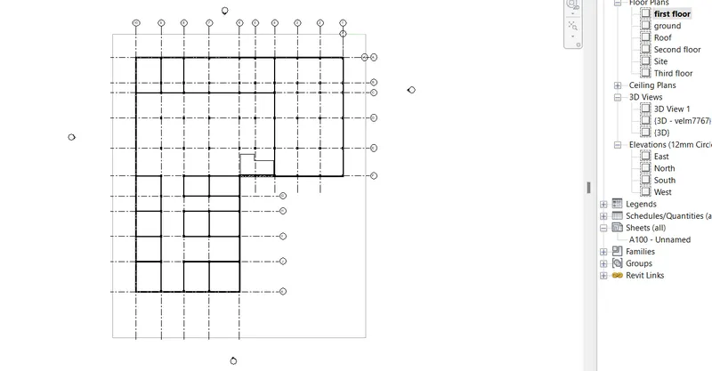
- Create components to add details to the rooms.
- Dropdown the component pannel under architectural tab.
- Select place a component.
- Start placing the component.
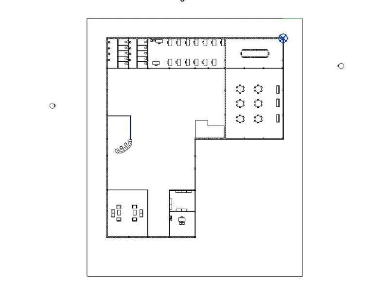
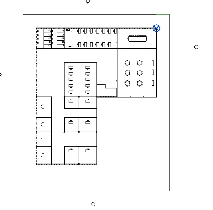
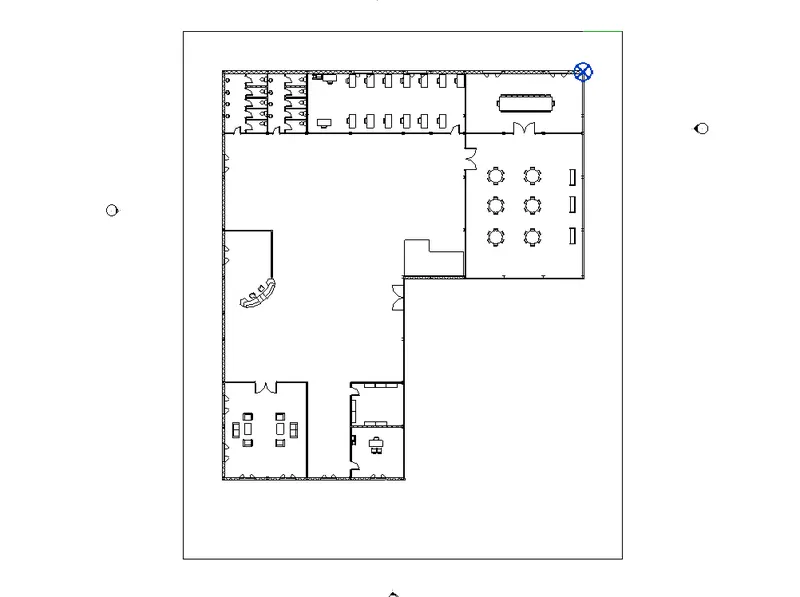
- Place doors and windows.
- Click doors under architecture tab.
- Slecte the type of door and place it to the desired place.
- Add stairs and elevators.
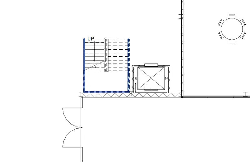
- Select stairs under architecture tab.
- Select straight type.
- Edit the properties of stair as width 1.5m, thread 0.3m and riser 0.15m
- Strat sketching the stair.
- Click load family.
- Select elevator-electric.
- Place it to the desired location.
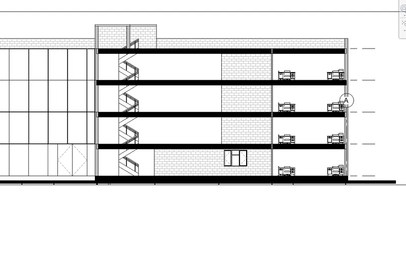
- Open any one section view.
- Select connected levels.
- Select the levels to connect.
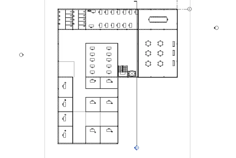
- Add lighting fixtures.
- Select place component.
- Click load family.
- Select the type of light and add to the building.
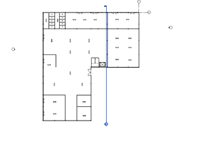
- Create celiing in the ground, first, second and third floor.
- Open ceiling plan.
- Add ceiling lights.
- Place topographic futures.
- Exterior lights.
- Select ectrior light from the lighting.
- Place it to the desired exterior locations.
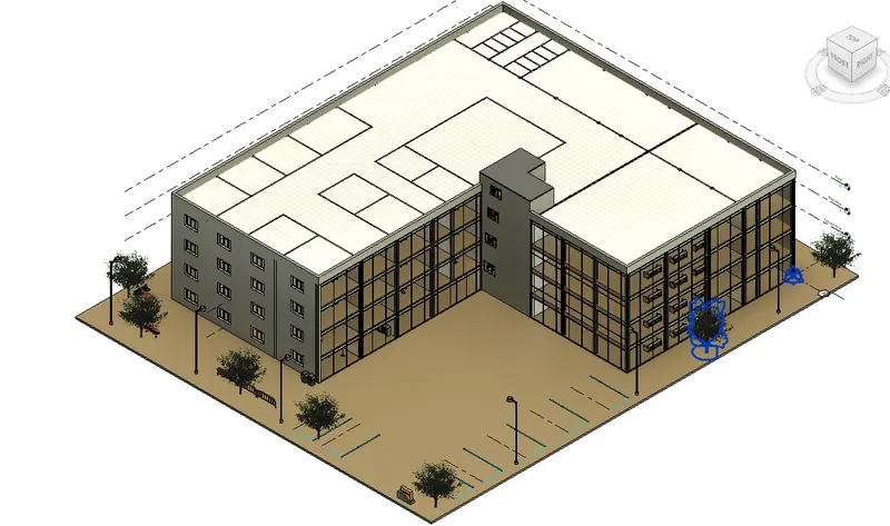
- Select site components from the massing and site tab.
- Select the type of tree and place it to the desired location.
Result:
The architectural components are included to the office building.
Wall layout with appropriate materials
Interior partition walls
Components like desk, chair and pulmbing fixtures
Components such as stairs and lift
Lighting fixtures
Topographic components
5) Provide a set of drawings in an architectural and structural model to list the following details with categories and appropriate sheet templates included
a. Floor Plans with Annotations
b. Elevations
c. Sections
Aim:
To list the following details with categories and appropriate sheet templates.
a) Floor plans with annotations
b) Elevations
c) Sections
Procedure:
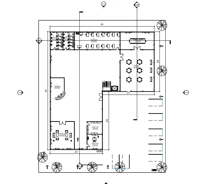
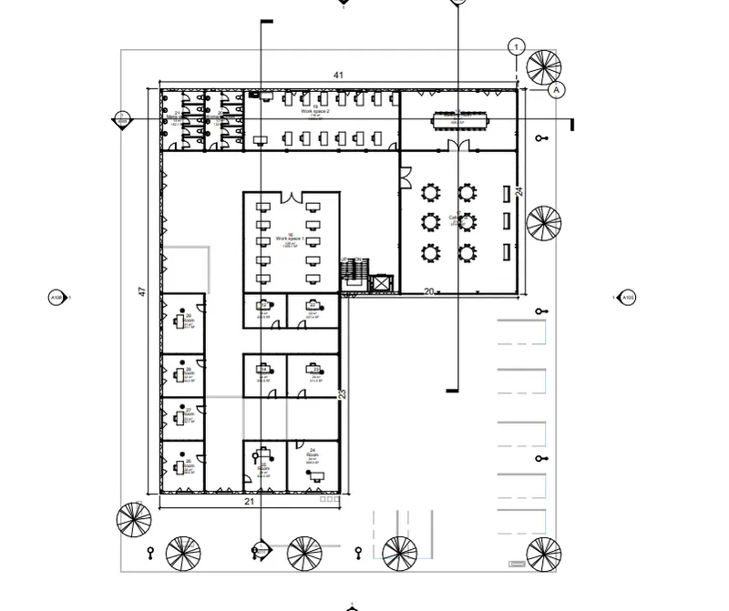
Annotate the floor plans by using the annotation tab. Select aligned dimension to start dimensioning the plans
Tag the rooms by using room tag under architecture tab.
Floor plans:
Ground floor plan:
First floor plan:
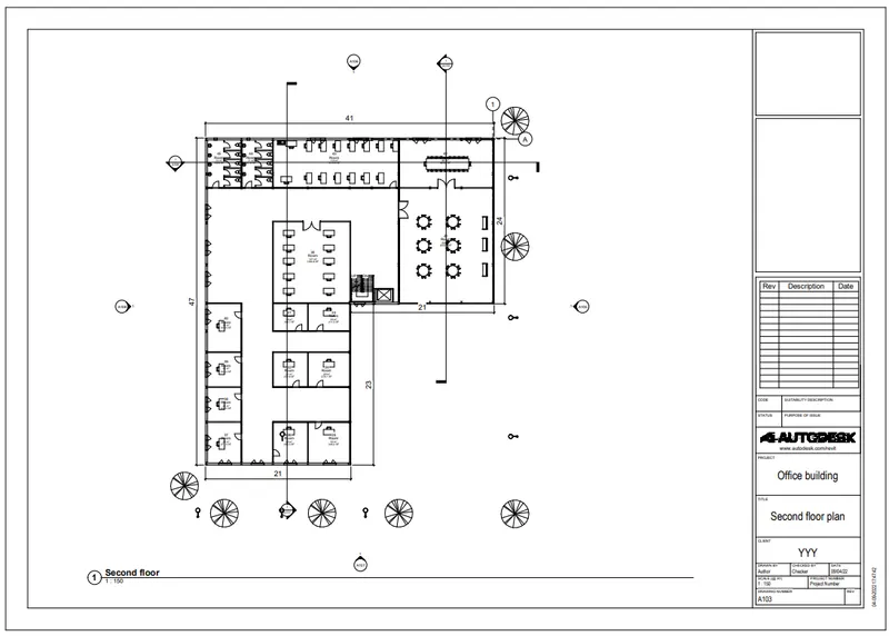
Second floor plan:
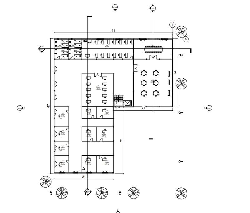
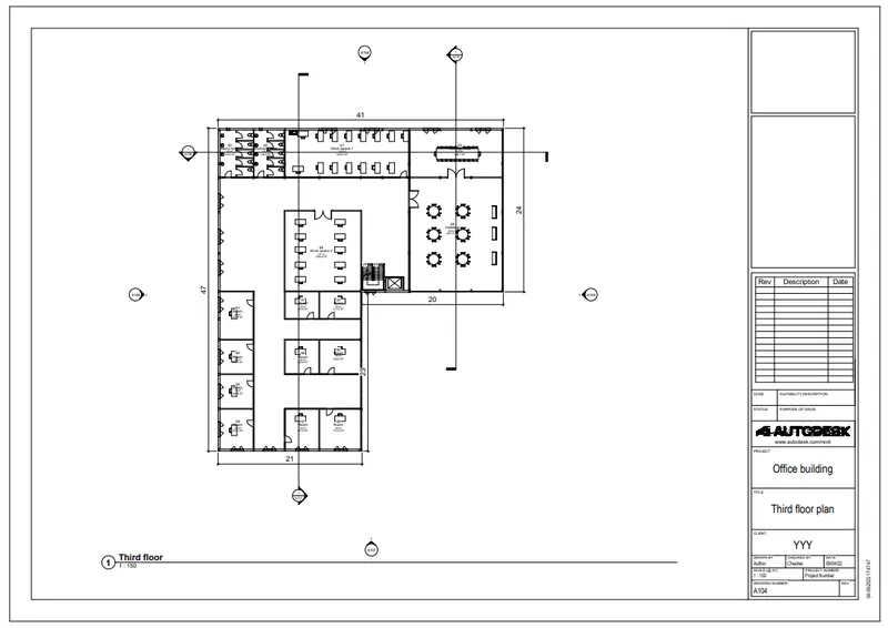
Third floor paln:
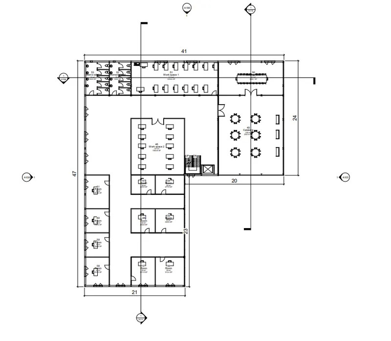
Floor plan templates:
Ground floor plan template:
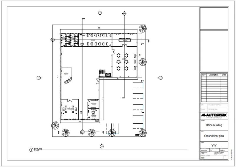
First floor plan template:
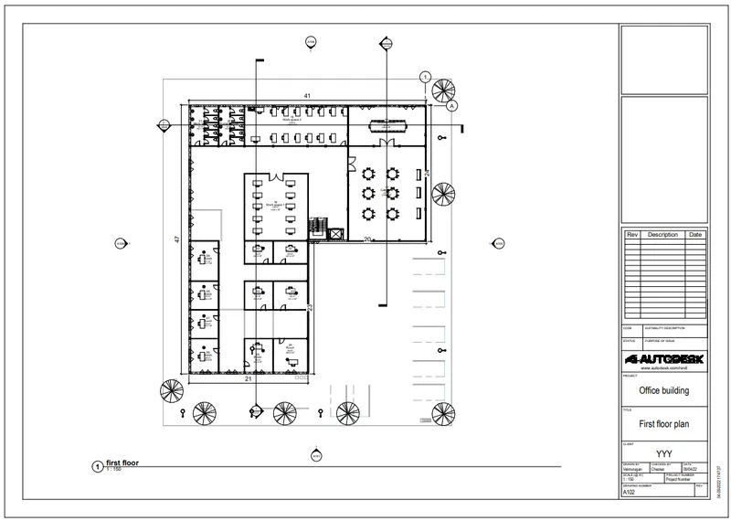
Second floor plan template:
Third floor plan:
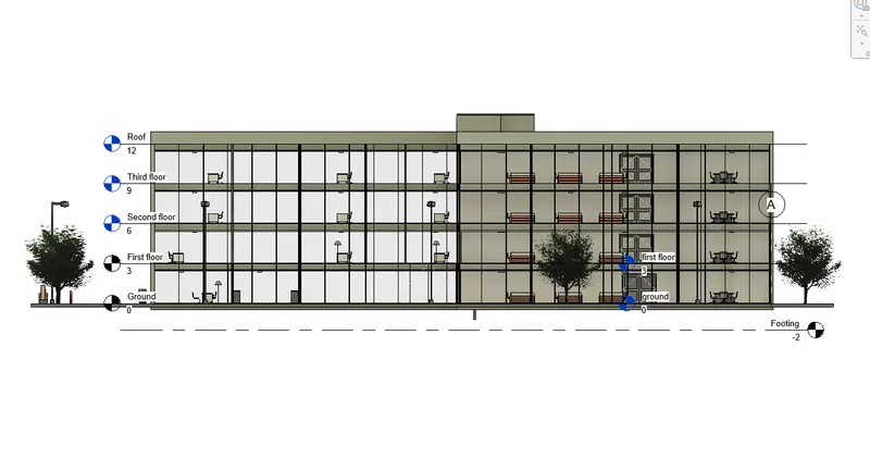
Elevation views:
East elevation:
North elevation:
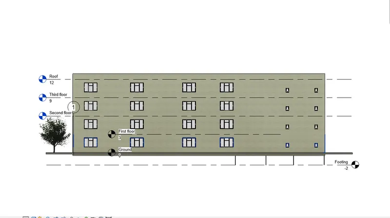
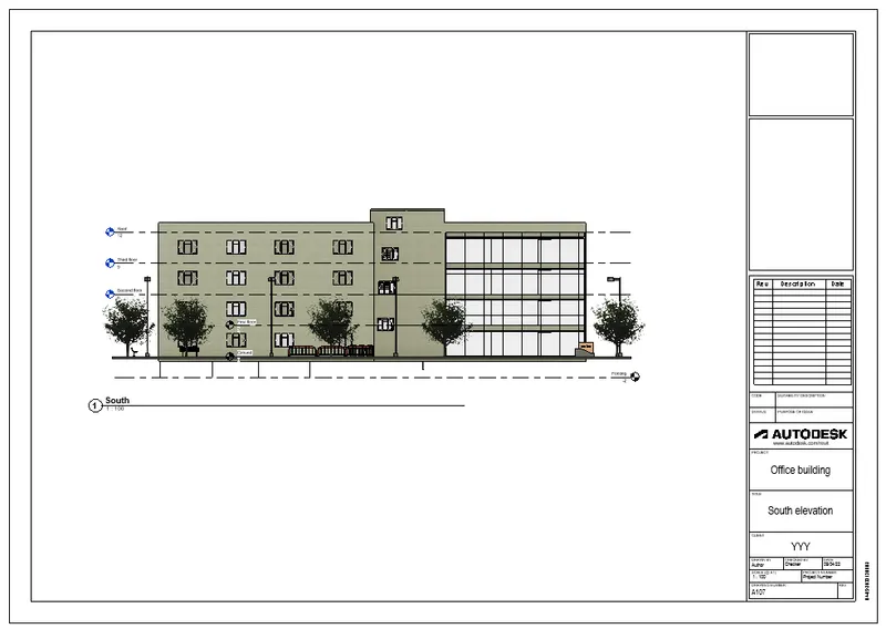
South elevation:
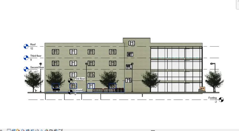
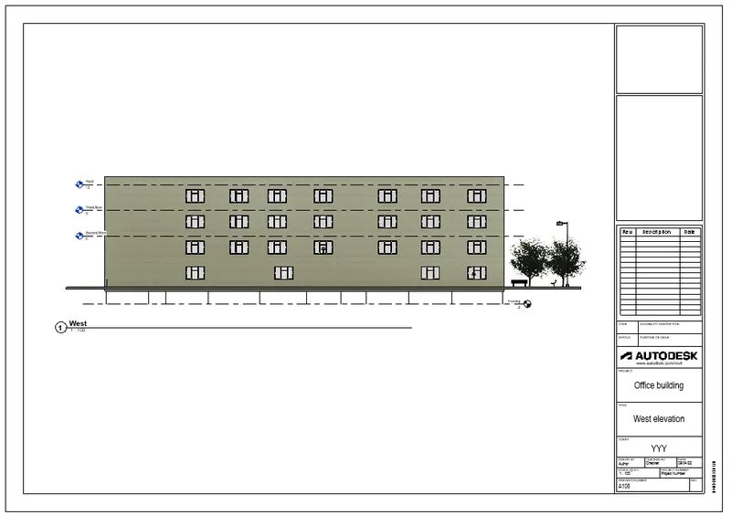
West elevation:
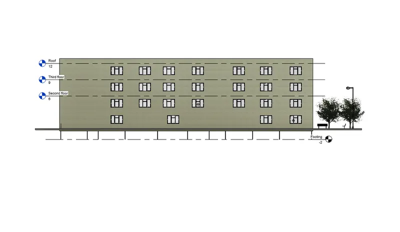
Elevation templates:
East elevation template:
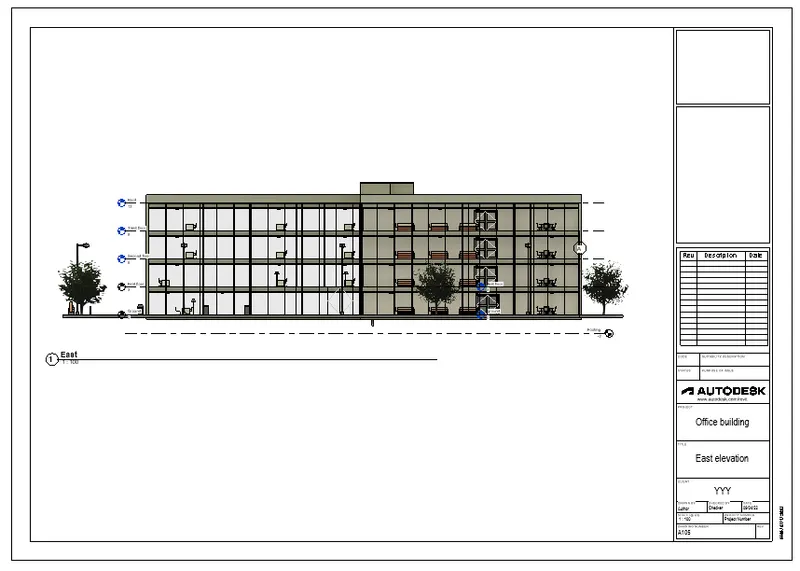
North elevation template:
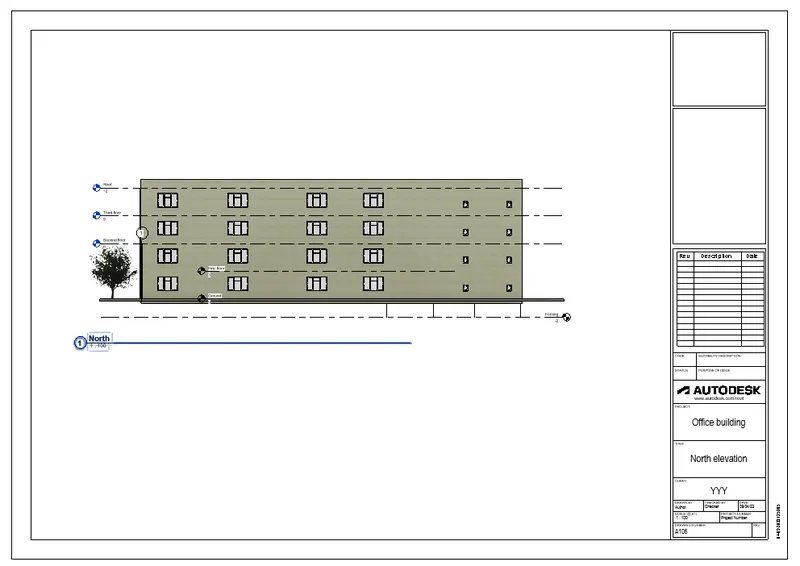
South elevation template:
West elevation template:
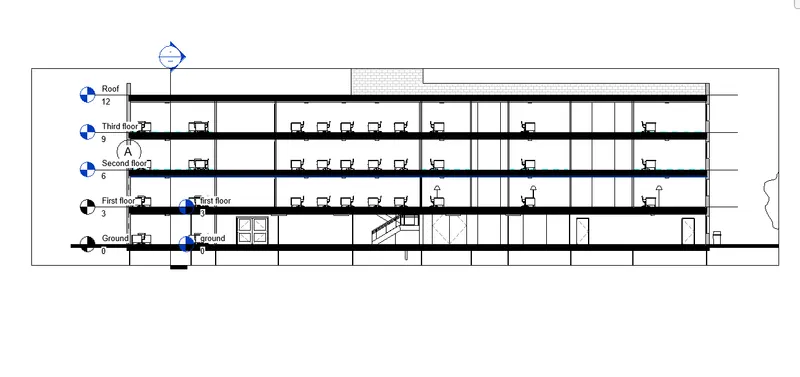
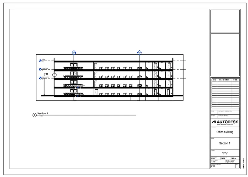
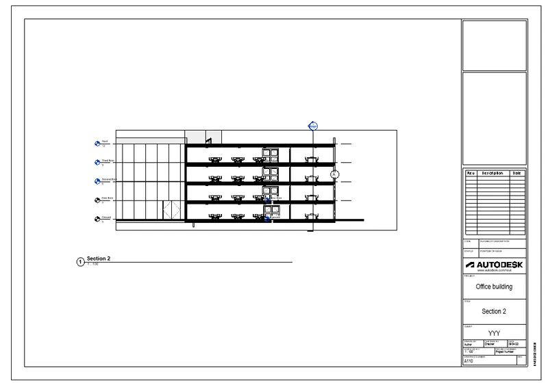
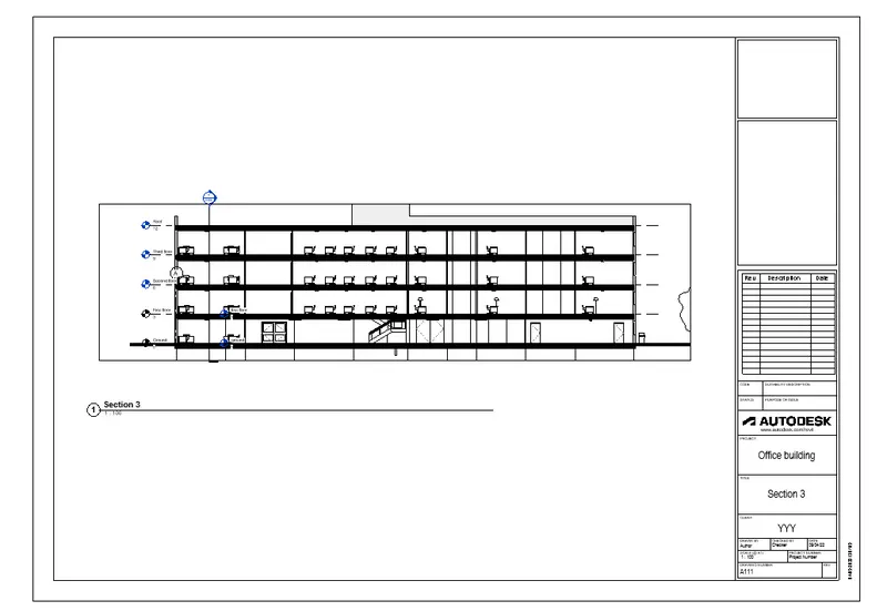
Section views:
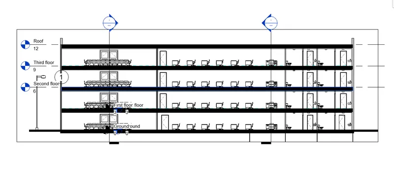
Section 1:
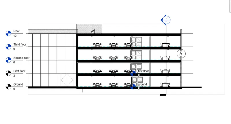
Section 2:
Section 3:
Section templates:
Section 1 template:
Section 2 template:
Section 3 template:
Result:
The following details with categories and appropriate sheet templates are created.
a) Floor plans with annotations
b) Elevations
c) Sections.
6) Using the Rendering settings, Render images of the 3D model produced and include the rendered images to the drawing sheets
a. Rendering from interior rooms
b. Rendering from out showing topographic features
c. Rendering through structural framing
Aim:
To create render images of the 3D model produced and include the rendered images to the drawing sheets.
a. Rendering from interior rooms
b. Rendering from out showing topographic features
c. Rendering through structural framing
Procedure:
- Place cameras in the required positions.
- Select render option under view tab.
- Set the render setting as required.
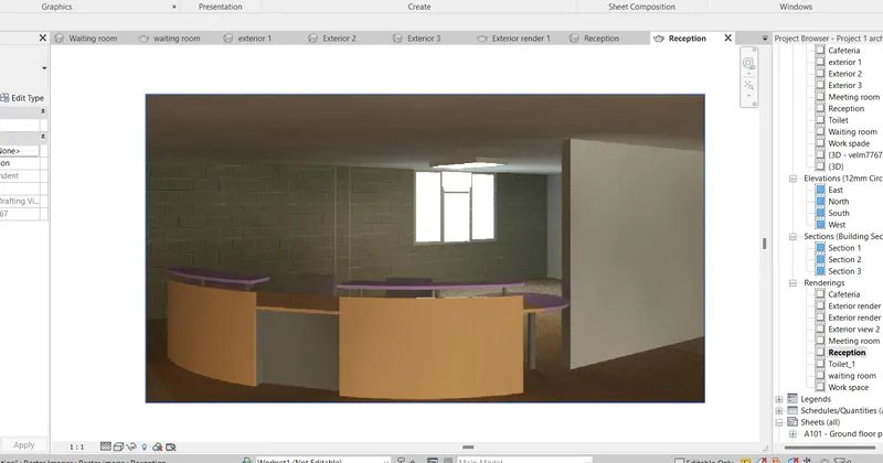
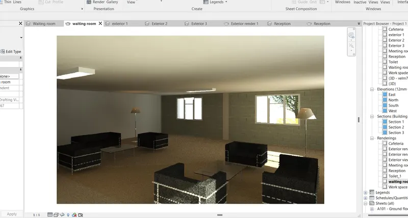
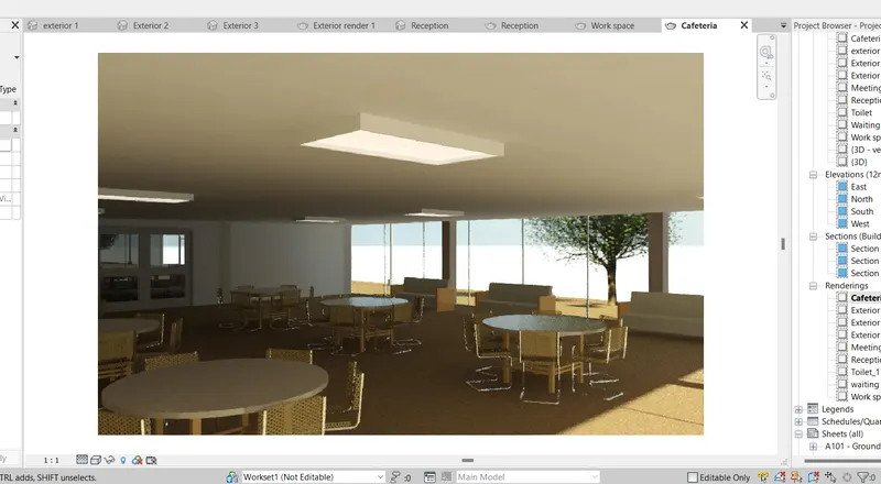
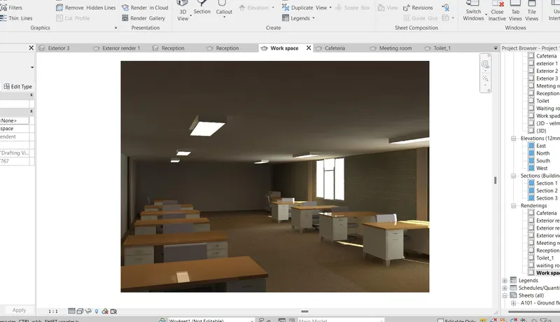
a. Rendering from interior rooms:
Reception:
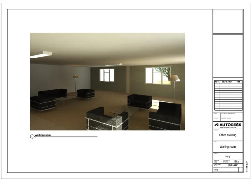
Waiting room:
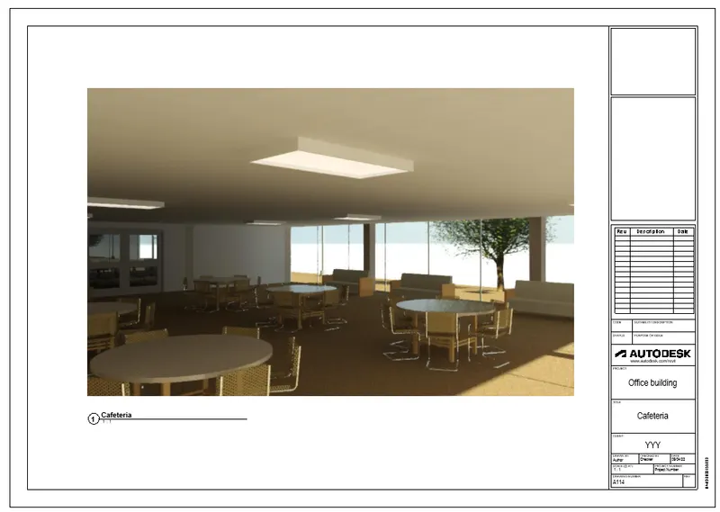
Cafeteria:
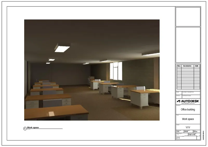
Work space:
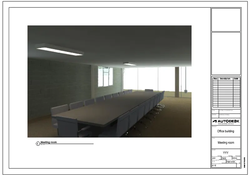
Meeting room:
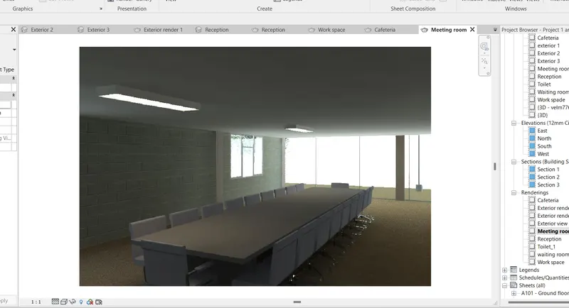
Toilet:
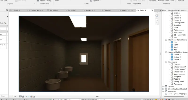
Office room:
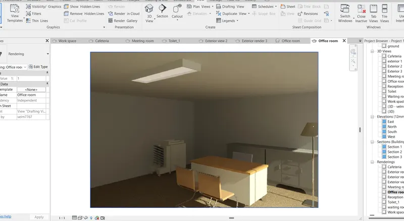
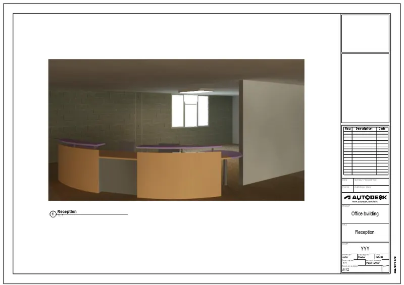
Drawing sheets:
Reception:
Waiting room:
Cafeteria:
Work space:
Meeting room:
Toilet:
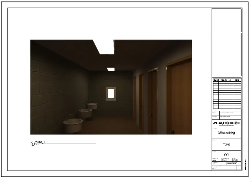
Office room:
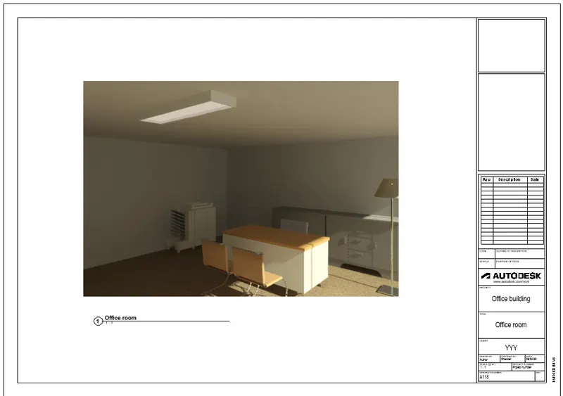
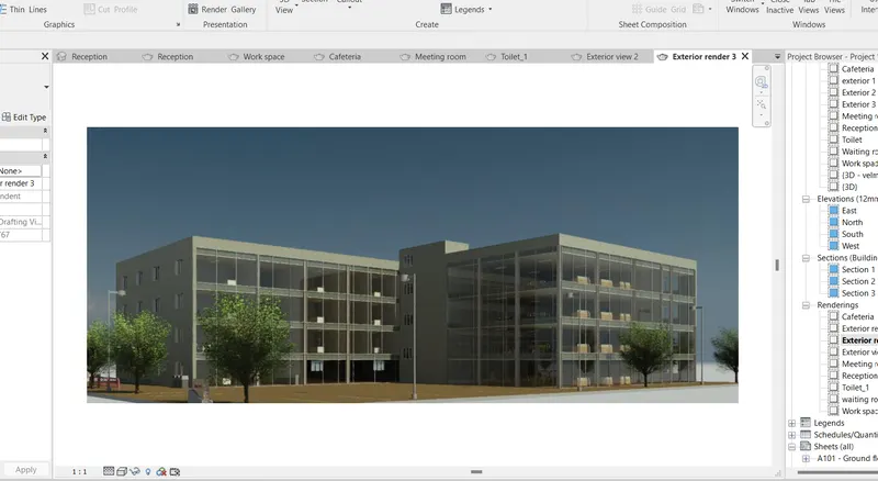
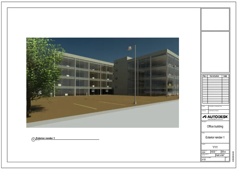
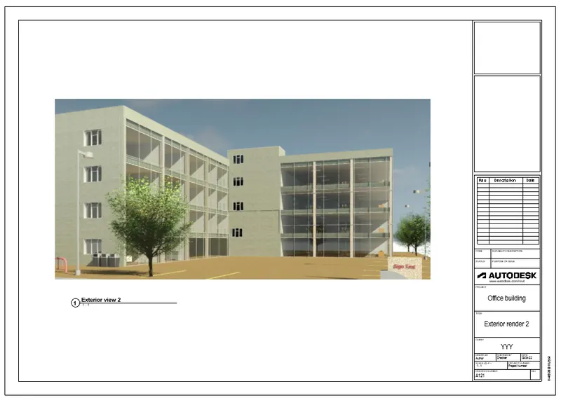
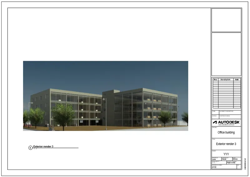
b. Rendering from out showing topographic features:
Exterior render 1:
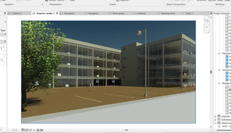
Exterior render 2:
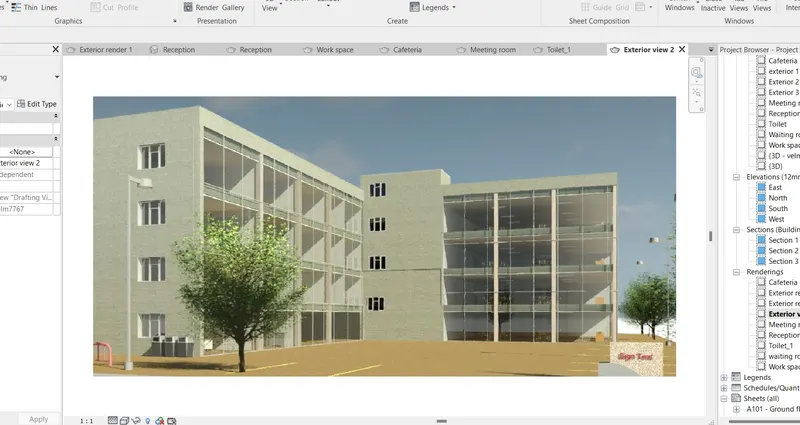
Exterior render 3:
Drawing sheets:
Exterior render 1 template:
Exterior render 2 template:
Exterior render 3 template:
C. Rendering through structural framing:
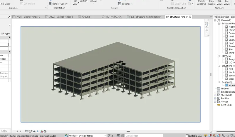
Structural framing template:
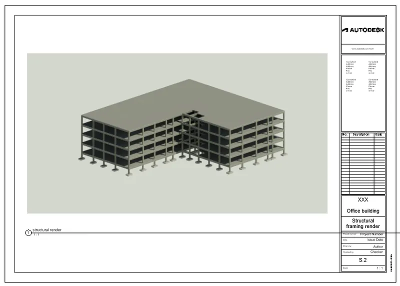
Result:
Render images of the 3D model produced is created and the rendered images to the drawing sheets are included.
7) Print the set of drawing sheets created and submit the drawings from the architecture and structure model.
Aim:
To print the set of drawing sheets created and submit the drawings from the architecture and structure model.
Procedure:
- Open file menu.
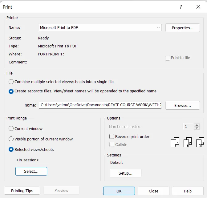
- Select print option.
- The print dialouge box will opened.
- Set the name as microsoft print to pdf.
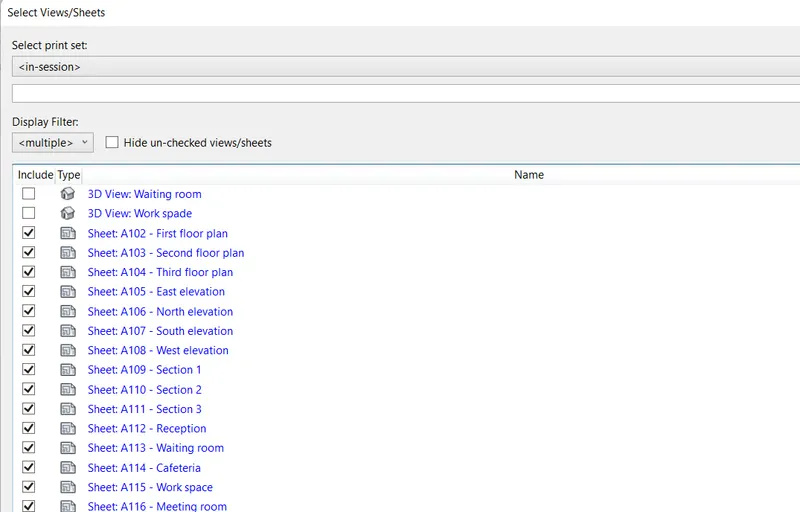
- Select Print range as selected views/sheets.
- Select all the sheets created.
- Click ok.
Plan, elevation and section:
Ground floor plan:
First floor plan:
Second floor plan:
Third floor plan:
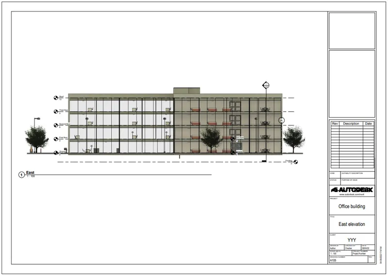
East elevation:
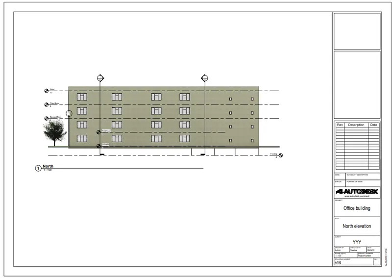
North elevation:
South elevation:
West elevation:
Section 1:
Section 2:
Section 3:
Interior and exterior render:
Reception:
Waiting room:
Cafeteria:
Work space:
Meeting room:
Toilet:
Office room:
Exterior render 1:
Exterior render 2:
Exterior render 3:
Structural framing:
Result:
The set of drawing sheets created are printed and the drawings from the architecture and structure model are submitted.