Creating Architectural and Structural model with 3D rendering using REVIT
Answer:-
1]I want to build Office Building.
2]
Modelling Requirements for the Office Building as per NBC based on the type of Structure.
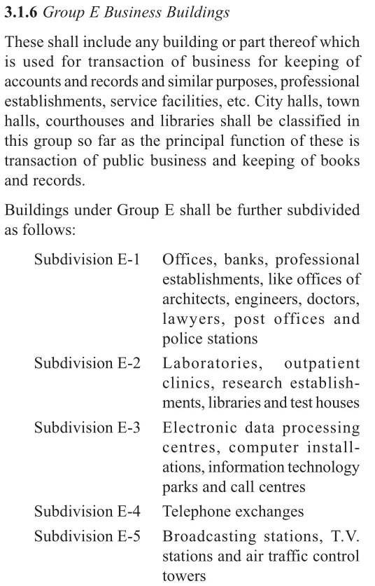
Type of Occupancy:
As per NBC part 4 Fire and Life safety
Clause No: 3.1.6
Business Building
Sub division E-3: Information Technology Park
F.A.R:
Type 2 Construction
Allowable FAR:- 2.9
Plot Area: 2695 m2
Total Built up area: 5790 m2
(No of Floors: 6 including Ground Floor)
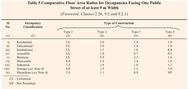
Calculated F.A.R is within the prescribed limits as per NBC
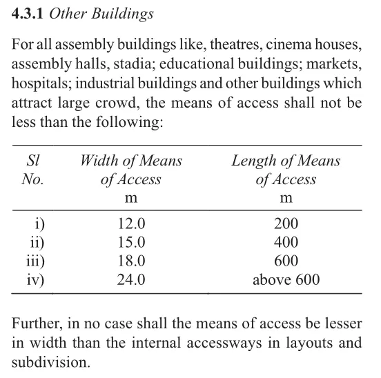
MEANS OF ACCESS:
The Width of Means of access shall not be less than 12 m
SETBACKS:
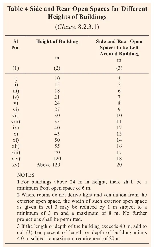
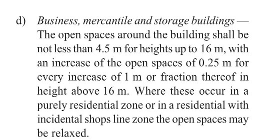
As per Part 3, Development Control Rules and General Building Requirements.
Clause No- 8.2.3.1 and table 4
Heigh of building is 25 m
So, provide side and rear open spaces to be 9m
STAIRCASE:
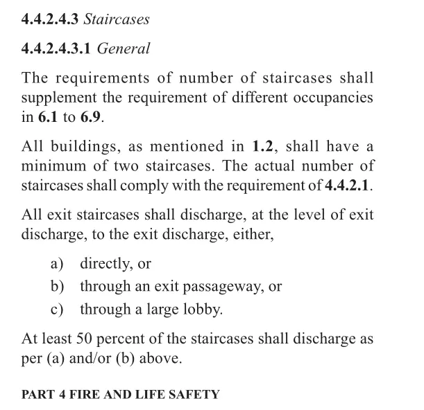
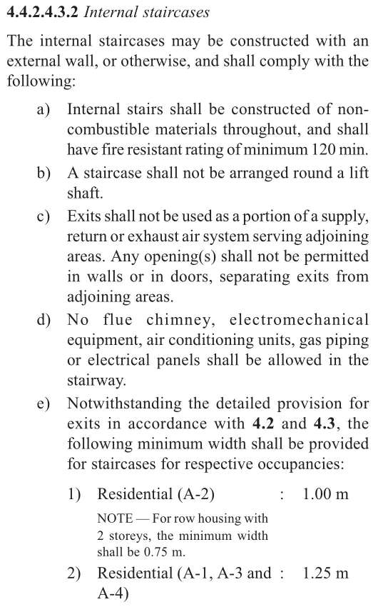
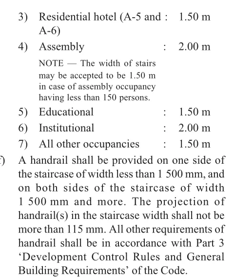
Provide the Stairs as per the Part 4, Fire and Life Safety
The building shall have a minimum of two staircases as mentioned in clause 1.2
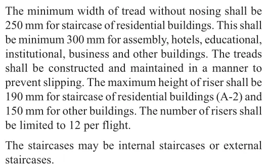
Width of tread: 250mm
Rise of Tread: 150mm
No of Risers per Flight: 12
Width of Staircase: 1.5 m
OFF-STREET PARKING SPACES:
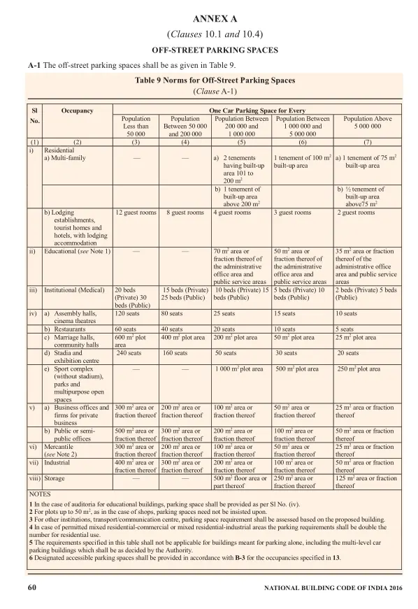
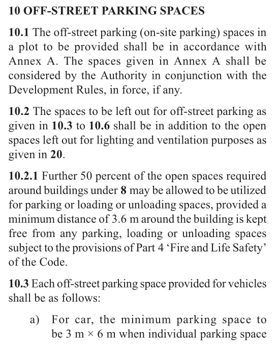
As per Part 3, Development Control Rules and General Building Requirements.
Clause No 10.1 an 10.4
We provided parking space as 300 m2
ARRANGEMENT OF LIFTS:
As per Part 8, Building Services from NBC
Clause 5,
FIRE EXTINGUISHERS:
As per Part 4, Table 7
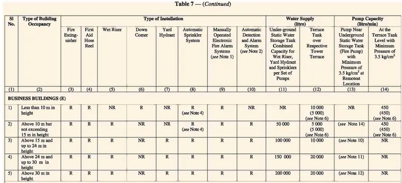
- One ABC powder extinguishers of 6 kgs. Capacity for every 8 cars at parking areas should be provided.
- One CO2 extinguishers of 4.5 kgs. Capacity should be provided near the entrance to the electrical room.
- One Mechanical Foam extinguishers of 9 litres capacity & one ABC powder extinguishers of 6 kgs. Capacity should be provided near the transformer.
- One Mechanical foam extinguishers of 9 litres capacity and one ABC powder extinguishers of 6 kgs. Capacity should be provided near the diesel generator.
- One CO2 extinguishers of 2 kgs. Capacity should be provided inside each lift machine room.
- One Water Mist type extinguishers of 4 litres & 9 litres capacity should be kept near each staircase landing at each floor.
3]
Aim-To create a structural model and include following components
- Foundation
- Columns
- Beams connected to Columns
- Floor
- Floor Opening
- Roof Framing/Truss
- Opening for elevator and stairs
Introduction-Revit offers different templates for Architectural, Structural, and MEP engineers to work easily based on the preloaded settings in the templates. When we open the Architectural Template, it will consist of both architectural and structural tabs.
The Architectural tab consists of walls, windows, doors, roofs, floors, etc that are used for architectural purposes and modeling whereas the Structural tab consists of structural walls, Columns Beams other Structural elements used for analysis.
By using structural tab we create foundation, column, beams, roof etc.
Procedure-
-Open Revit softwear with structural template
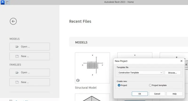
-Save file as a Structural Model
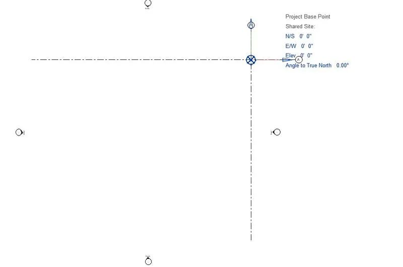
-Go to Architecture tab>Select grid>Draw horizontal and vertical grids
-Rename grids, horizontal as A and vertical as 1
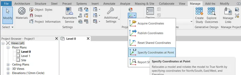
-Go to Manage>Select coordinate>Select specify coordinate
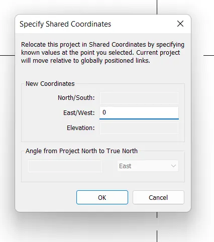
-click on grid and set 0 as a value for the both grids
-Type VG>Select Site>Tick on project base point
-Go to Insert tab>Select Revit links>Select Architecture file
-In Architecture file we already created grids and levels fo rthis project with same coordinate
-After opening the Architecture file
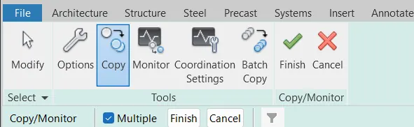
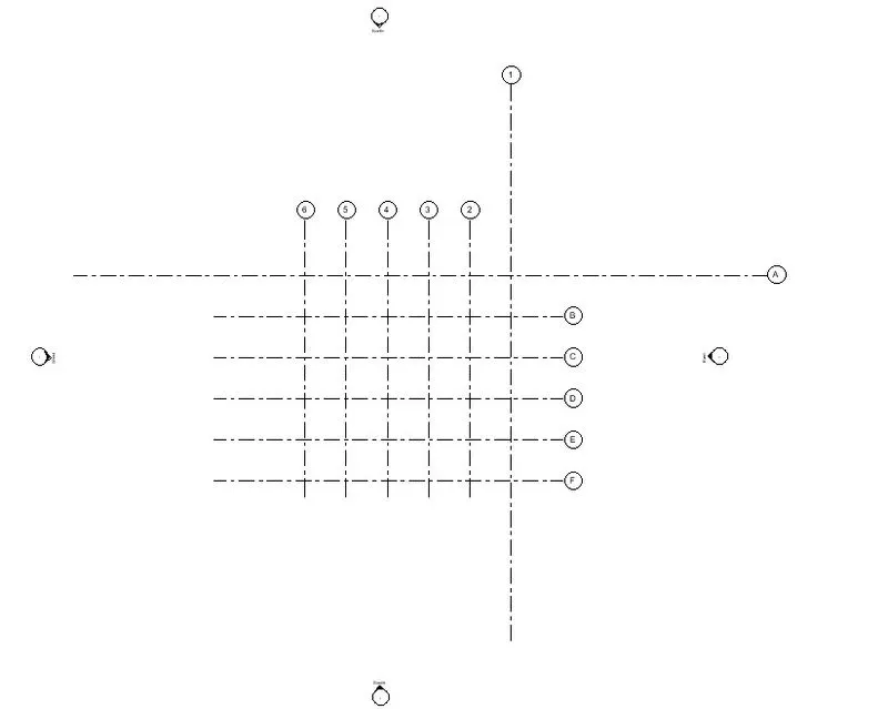
-Go to Collaborate>Select copy>Select links option>Select link>Select copy, tick on multiple>Select all grids that we want to copy>Finish
-To draw Foundatiion
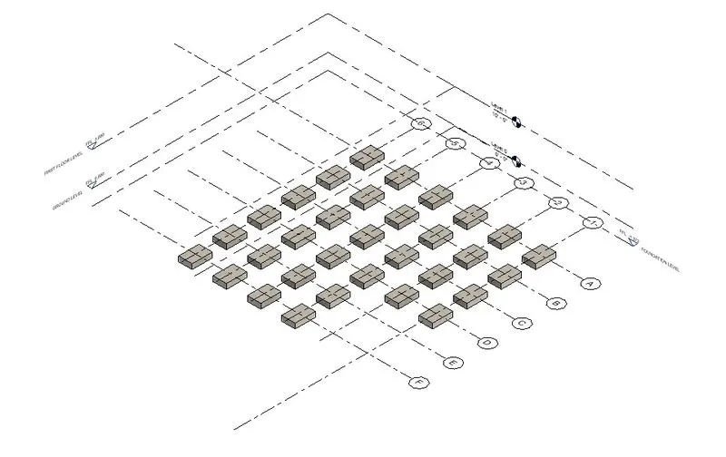
-Go to structure tab>Select Isolated>Select appropriate size of footing>Select grids>Select all grids>Ok

-Draw in foundation level
-Go to Structure tab>Select Column>Select concrete with appropriate size>Seelct at girds option>Select all grids>Ok
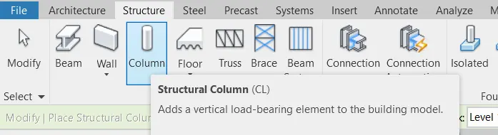
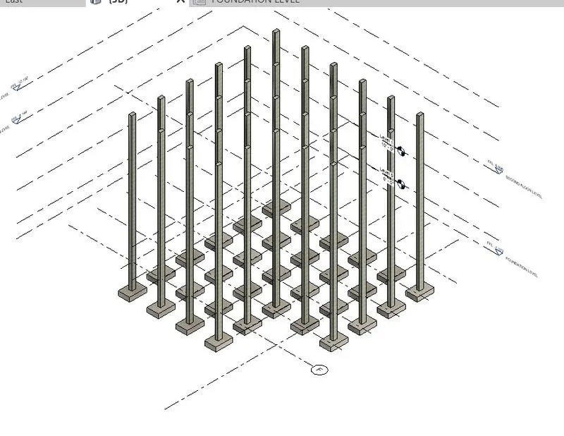
-In project browser, base level is Foundation level and top constrain is Ground level
-Now Go to Ground level Select all column>Click on copy to clipboard>Paste it to Aligned to selected level>Select first floor level, second floor level, third floor level, roof level
-Again go to structure tab>Select beams>Select at grids>Select transverse grids first then longitudunal grids
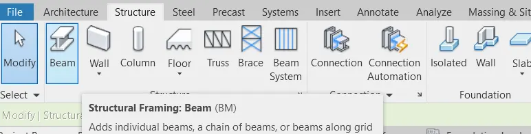
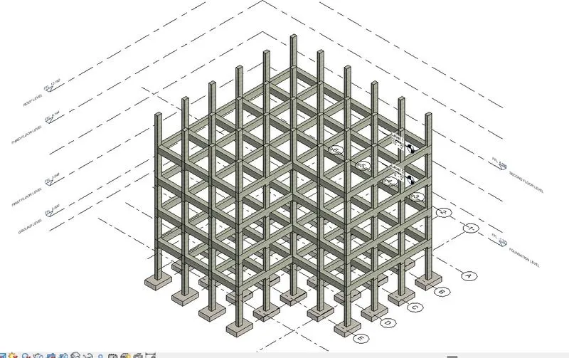
-In project browser select edit, for transverse beam make duplicate of given beam as 450x600, And for longitudinal beam we take as it is i.e. 300x600mm
-Firstly all beams are created at Ground level, Now select all beams>Select copy to clipboard>Paste it to aligned selected levels>Select first floor level, second floor level, third floor level
-Go to Structural tab>Select floor>Select draw lines option>OK
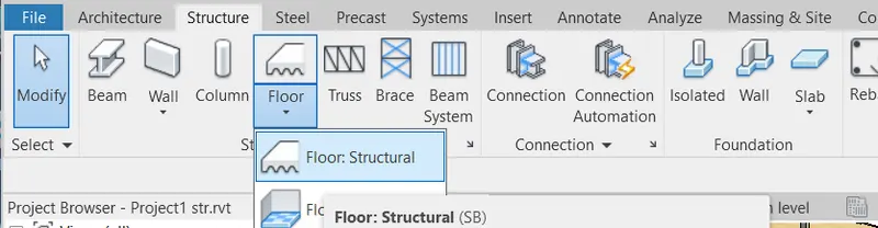
-In properties go to edit type>Select thickness>Select appropriate material>Ok
-This floor draw at Ground floor level. Now select floor>Select copy to clipboard>Select paste Aligned to selected level>Select first floor level, second floor level, third floor level
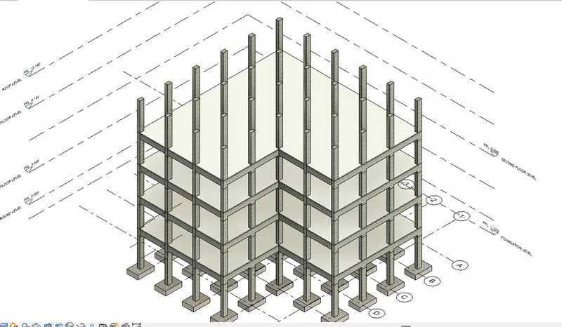
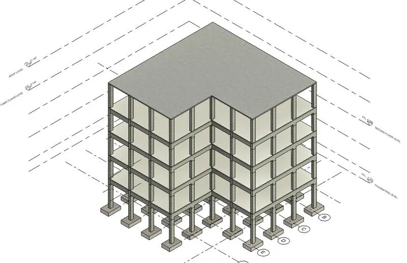
-For Roof
-Go to Architecture tab>Selct roof by footprint>Select draw option
-In properties select edit type>Select 125mm as thickness>Select material give appropriate material to it
-In project browser chnage slope as 0
-To create shaft opening for Stairs
-Go to Architecture tab>Select shaft>Select draw line option and draw boundary for opening
-First draw opening from first floor to third floor and then seprately for Roof level
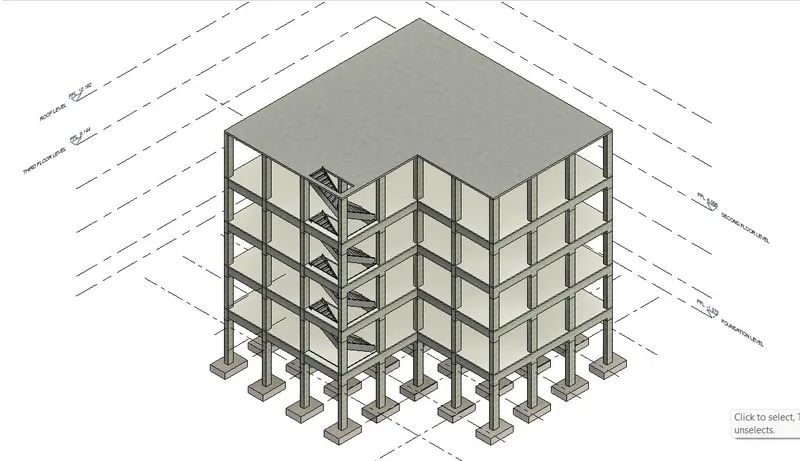
Result-
In this Structural Model we created Foundation, Columns, Beams, Floors, Roof and oprning for stairs,
4]
Aim-To create following components in Architecture Model
- Wall Layout with appropriate material and finishing
- Exterior façade with fancy finish
- Interior Partition walls to size rooms
- Components to add details to a room like Desk, chair, Lighting, Plumbing fixtures
- Add components such as stairs and Elevators
- Have at-least one side of the building with curtain walls and Glass panels
- Include interior and exterior Lighting fixtures
- Place proper topographic components from outside ( trees, parking, plants) to add details to the model.
Introduction-Revit offers different templates for Architectural, Structural, and MEP engineers to work easily based on the preloaded settings in the templates. When we open the Architectural Template, it will consist of both architectural and structural tabs.
The Architectural tab consists of walls, windows, doors, roofs, floors, etc that are used for architectural purposes and modeling whereas the Structural tab consists of structural walls, Columns Beams other Structural elements used for analysis.
Procedure-
-In this file we already created grids and levels
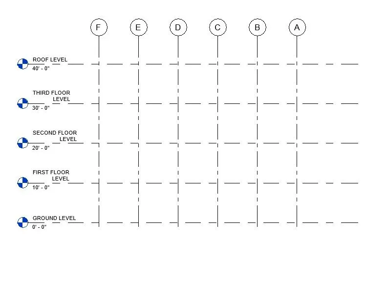
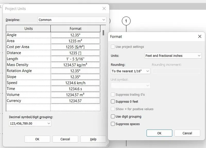
-Set unit by typing UN in feet and inches
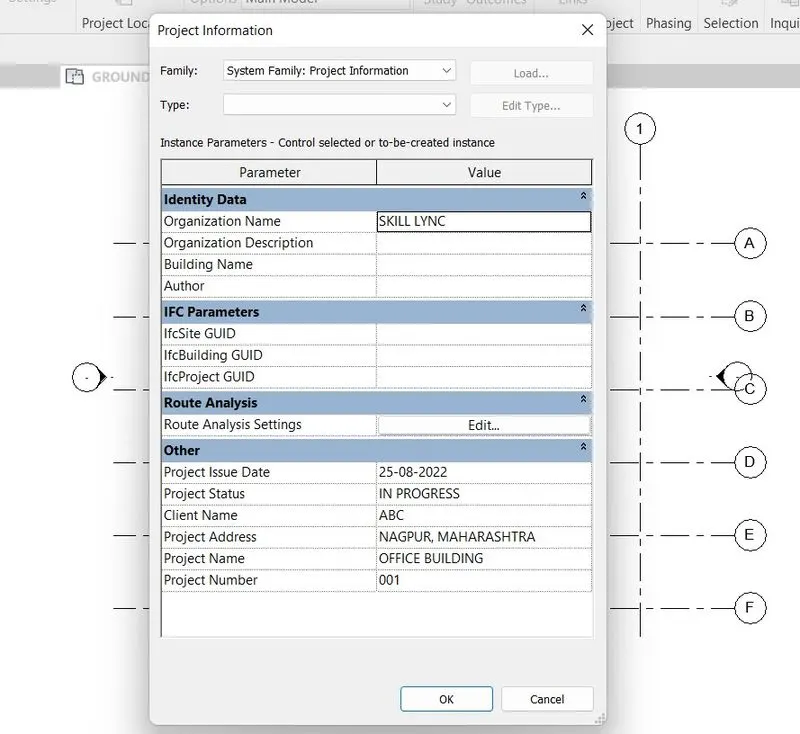
-Now Go to Manage>Select Project information>Fill up all the details
-Go to file>Select Save as>Select project>Click on Options set backup>Ok
-Go to Architecture tab>Select architectural wall>In properties >Select Edit type>Create Duplicate>EXT WALL>Select structure edit>Give thickness 9">Give materrial Paint whitw lining with color pink shade
-Go to Architecture tab>Select architectural wall>In properties >Select Edit type>Create Duplicate>INT WALL_1>Select structure edit>Give thickness 9">Give materrial Concrete precast
-Go to Architecture tab>Select architectural wall>In properties >Select Edit type>Create Duplicate>INT WALL_2>Select structure edit>Give thickness 6" >Give materrial Render beige smooth
-Go to Architecture tab>Select architectural wall>In properties >Select Edit type>Create Duplicate>INT WALL_3>Select structure edit>Give thickness 6" >Give materrial Brick engineering grey
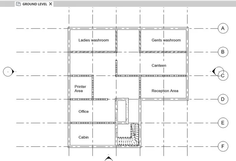
-Draw all walls as per the plan
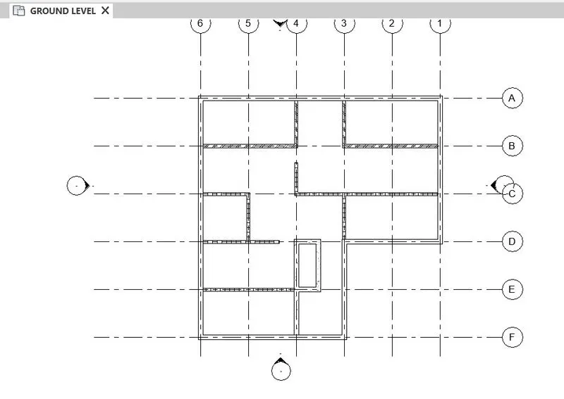
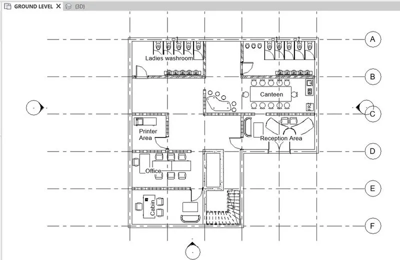
-Go to Annotate>Select text>Give text to each room to better understand
-To add Floor
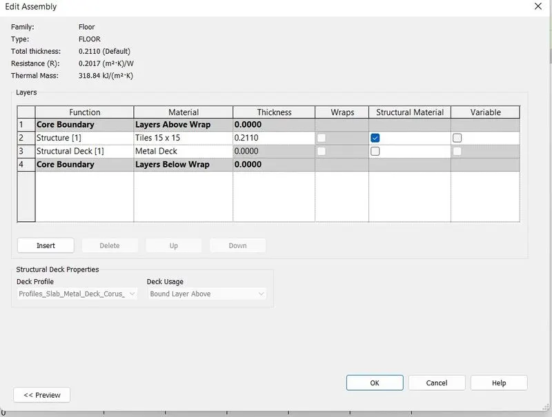
-Go to Architecture tab>Select Floor>In properties>create Duplicate FLOOR>Select structure edit>Select material TIle>give thickness 6"
-Staircase
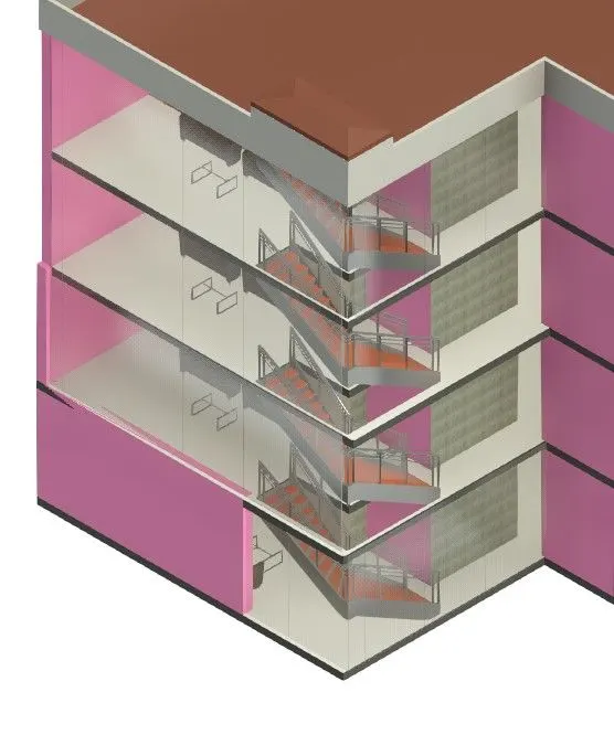
-Go to architecture>Select stair>Select L-shape winder stair>draw>In properties select base as Ground floor level and top is First floor level
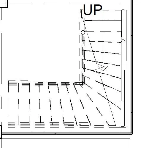
-Select railing change it to Glass Railing
-Copy this walls, Stairs, Floor to First floor,Second floor, Third floor
-Select elements that we want to copy>Click on COPY TO CLIPBOARD>Select PASTE>Select aligned to select levels
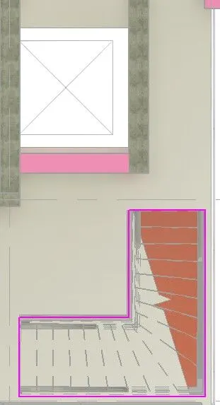
-To create openong for Lift ans Stair
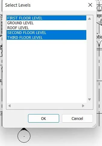
-Go to Architecture>Select shaft>Select draw line option, draw boundary as per stairs>In project Browser set base as first floor level and top as third floor level
-Go to Architecture>Select shaft>Select draw line option, draw boundary as per lift opening>In project Browser set base as first floor level and top as third floor level
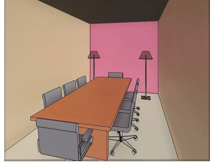
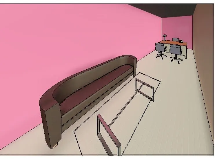
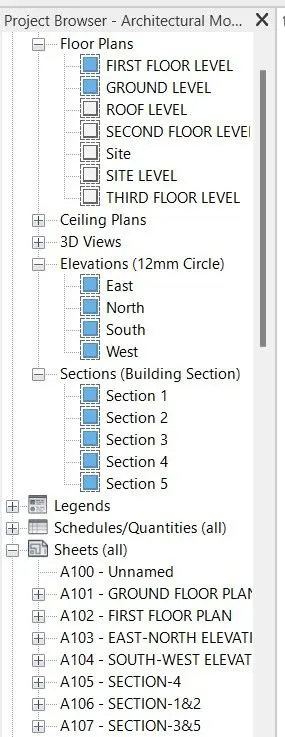
-Add componets as per room requirement
-Go to Insert>Select Load autodesk library>Select Furniture>Select Table option>Select tables>LOAD
-Go to Insert>Select Load autodesk library>Select Furniture>Select chair option>Select chair>LOAD
-Go to Insert>Select Load autodesk library>Select Furniture>Select seating option>Select sofa>LOAD
-Go to Insert>Select Load autodesk library>Select Special equipment>Select office appliance option>Select printer>LOAD
-Go to Insert>Select Load autodesk library>Select Special equipment>Select domestic option>Select kitchenette small and fridge>LOAD
-Go to Insert>Select Load autodesk library>Select Plumbing>Select Fixtures option>Select toilet cubicles, sinks, water closets>LOAD
-Go to Insert>Select Load autodesk library>Select Plumbing>Select Fixtures option>Select urinal_2>LOAD
-Place each and every componets from PROJECT BROWSER, select respective families for every componets and DRAG it to plan.
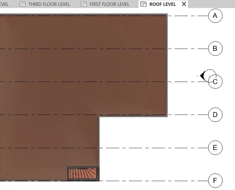
-Roof
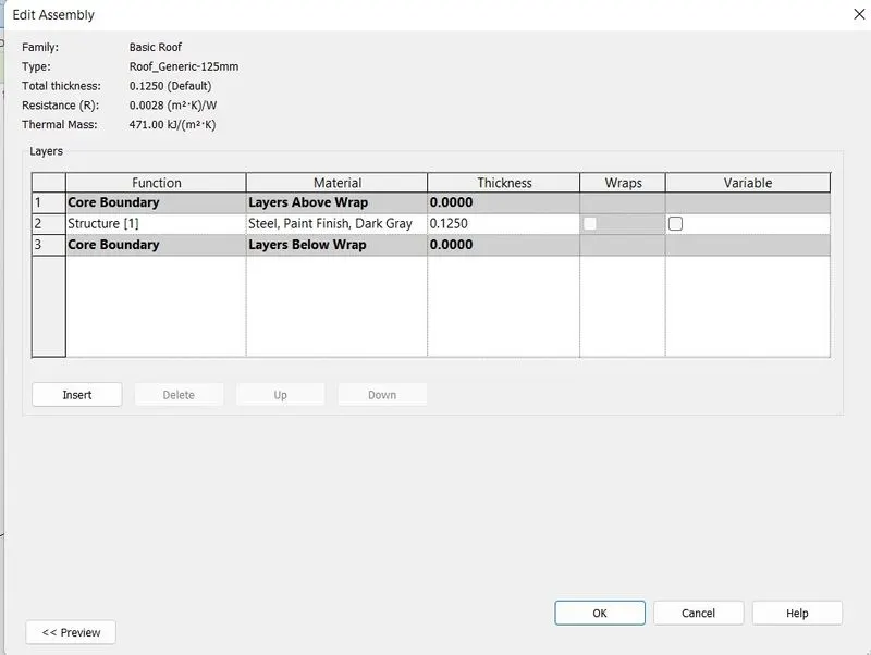
-Go to architecture>select roof>Select rrof by footprint>In project browser select edit type>Select strure edit give thickness 125mm and material to it
-Create Shaft for stair same as per previous
-Select front walls to make it in glass wall
-Select wall>In project browser select Curtain wall Exterior glazing
-For Internal lighting fixture
-Go to Insert>Selct load autodesk library>Select lightinng>Seelct architecture>Select interior>Select lamps>LOAD
Topographic component
-Go to Massing and site>Seelct topposurface>Select place point with elevarion 0, select place point with elevation 0.1>Click tick
-Create in project browser site
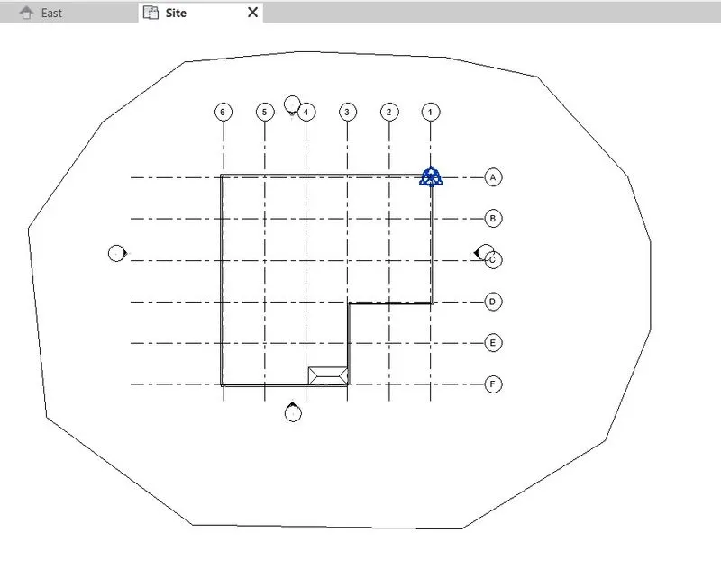
-Now create compound wall with 100mm thickness and 2000mm height
-Go to Insert>Select load autodesk family>Select parksing>Select parking std bays and bike stand>LOAD
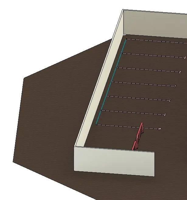
-Now add plants, bench and exterior lights
-GO to insert tab>Seelct autodesk family>Select planting>Select plants>LOAD
-GO to insert tab>Seelct autodesk family>Select lighting>Select lights>LOAD
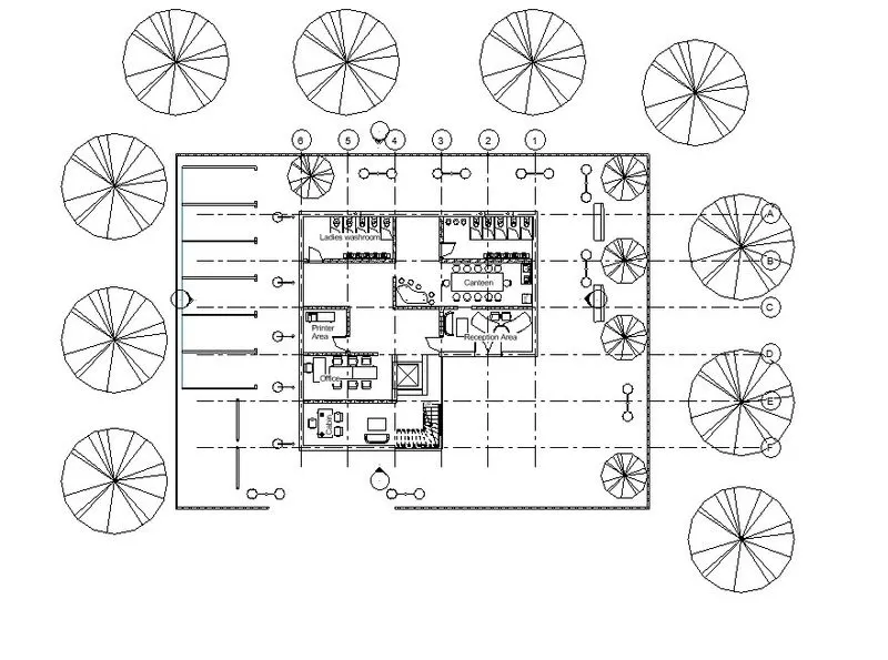
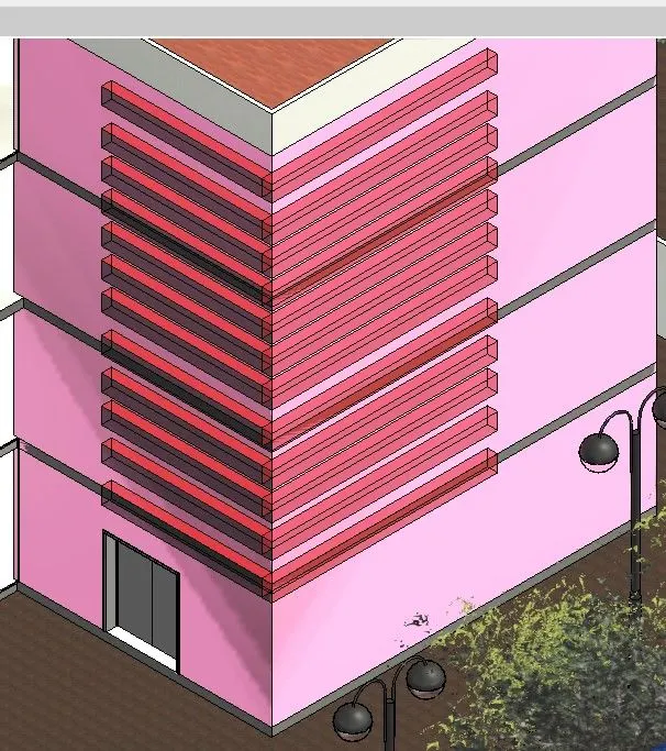
-To add exterior fancy finish
-GO to architecture>Select component>Select Model in place>select generic model>Select extrusion>Select set plane>Select plane where we wanto to add component>seelct draw line option and draw design as per your convienence>In project browser set elevation 0.25 and add material to it.>Finish
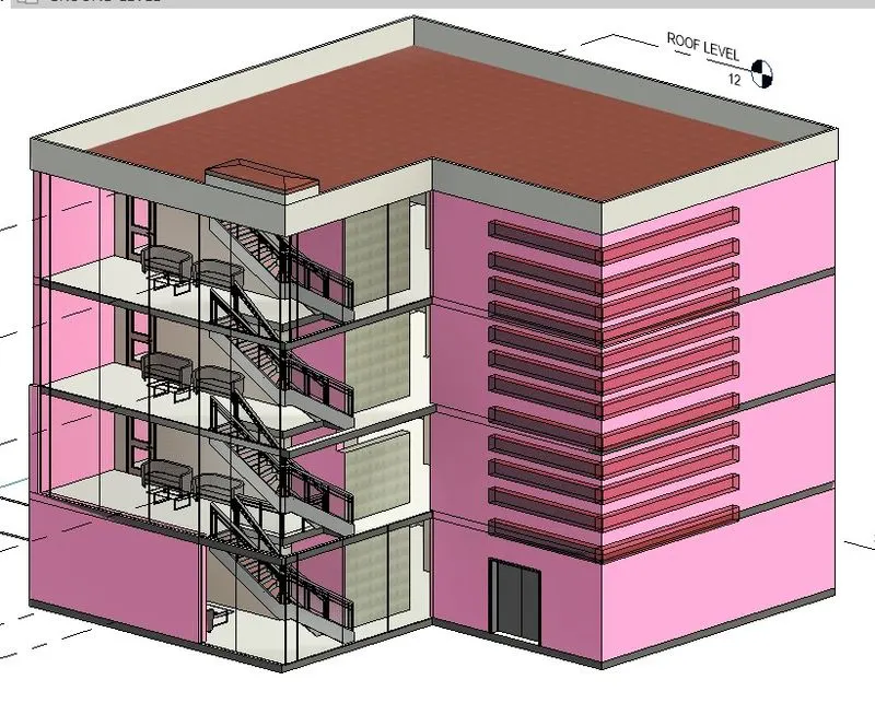
Result-
All the architecture components are drawn in this plan.
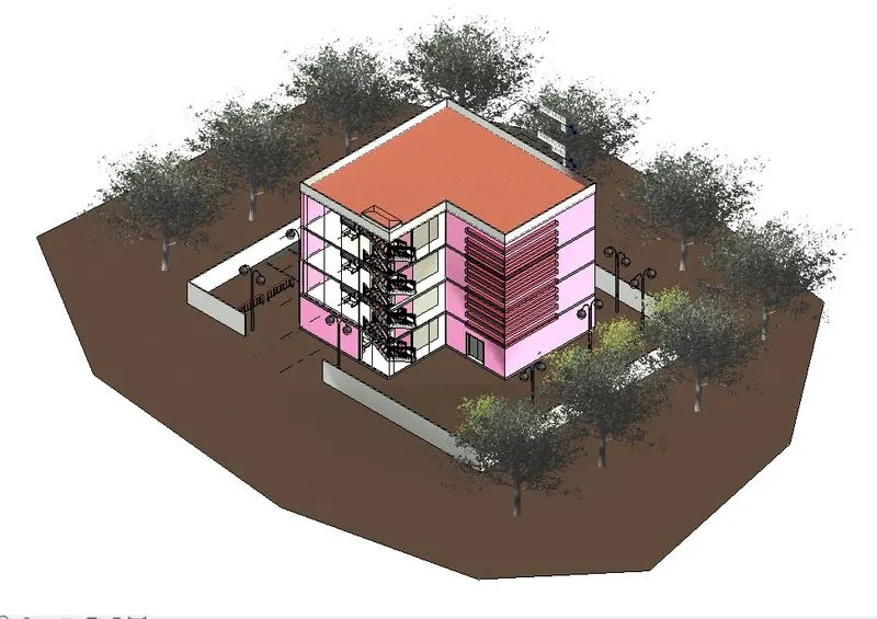
5]
Aim-Provide a set of drawings in an Architectural model and structural model using appropriate sheets to list the following details
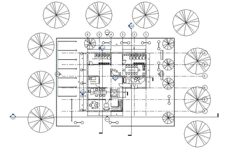
- Floor plans with Annotations
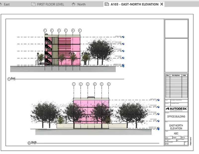
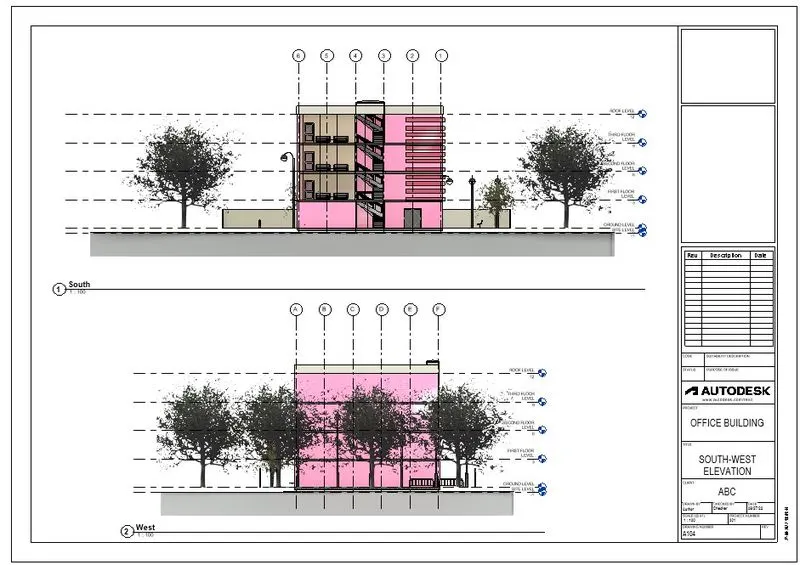
- Elevations
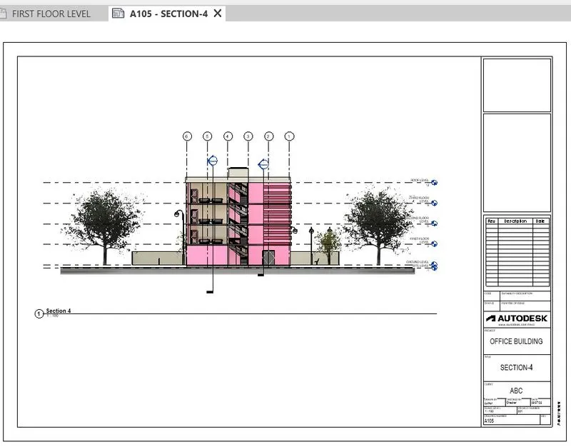
- Sections
Introduction-Revit offers different templates for Architectural, Structural, and MEP engineers to work easily based on the preloaded settings in the templates. When we open the Architectural Template, it will consist of both architectural and structural tabs.
The Architectural tab consists of walls, windows, doors, roofs, floors, etc that are used for architectural purposes and modeling whereas the Structural tab consists of structural walls, Columns Beams other Structural elements used for analysis.
We can add various sheet which include floor plan, sections and elevation
Procedure-
-First provide annotation to floor plans
-Go to annotate>Seelct aligned option>Select each room wall to give dimension>
-Then Go to view>select sheet>Se;ect std sheet>Ok
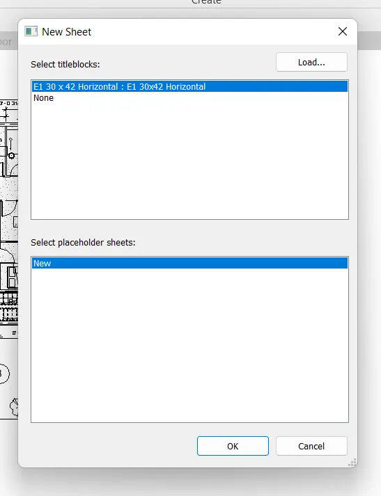
-Add details in sheet
-Now in peoject browser select ground floor plan and drag it in sheet
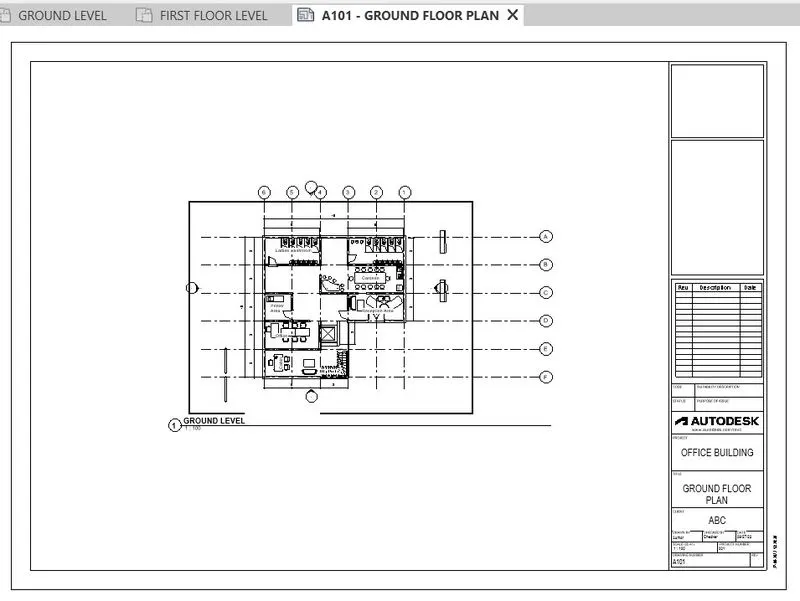
-Similarly for first floor plan sheet
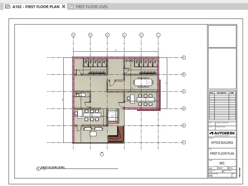
-Go to view>select sheet>Se;ect std sheet>Ok
-Add details in sheet
-Now in peoject browser select ELEVATION and drag it in sheet
-Go to view>select section>draw section where we want to cut the building
-Go to view>select sheet>Se;ect std sheet>Ok
-Add details in sheet
-Now in peoject browser select SECTION and drag it in sheet
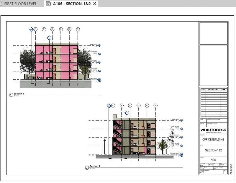
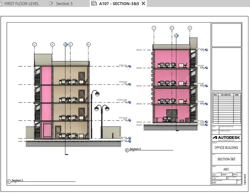
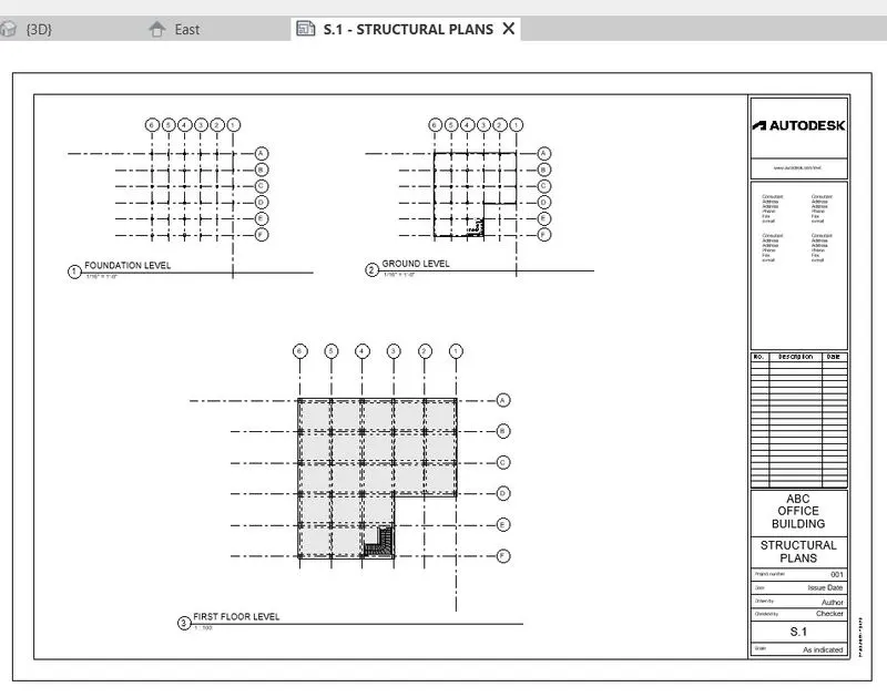
STRUCTURAL PLANS SHEET
-Go to view>Select sheet>there is teo option select metric sheet>Ok
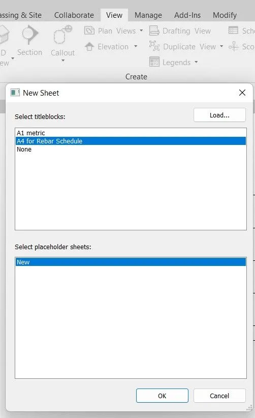
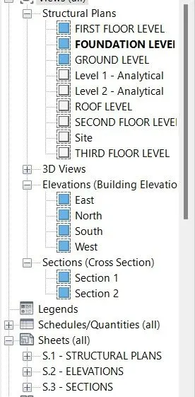
-In project browser select structural plans and drag it into sheet
-Go to view>Select sheet>there is teo option select metric sheet>Ok
-In project browser select elevations and drag it into sheet
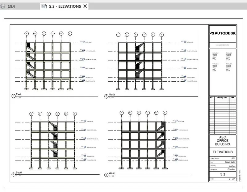
-Go to view select sections and add in plan
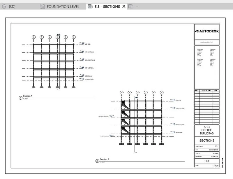
-Go to view>Select sheet>there is teo option select metric sheet>Ok
-In project browser select sections and drag it into sheet
Result-
All set of drawing in Architectural and Structural Model by using sheet are created.
6]
Aim-To render images of the 3D model produced and include the rendered images to the drawing sheets
a. Rendering from interior rooms
b. Rendering from out showing topographic features
c. Rendering through structural framing
Introduction-Revit offers different templates for Architectural, Structural, and MEP engineers to work easily based on the preloaded settings in the templates. When we open the Architectural Template, it will consist of both architectural and structural tabs.
The Architectural tab consists of walls, windows, doors, roofs, floors, etc that are used for architectural purposes and modeling whereas the Structural tab consists of structural walls, Columns Beams other Structural elements used for analysis.
Procedure-
-First set proper view of building
-Go toview>Select Render>Set all the information
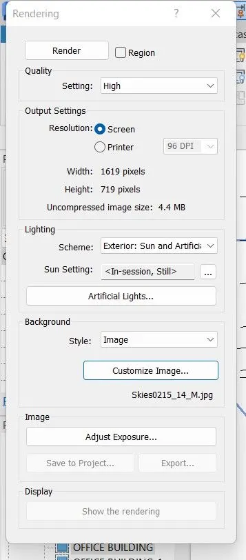
-Save the project by appropriate name
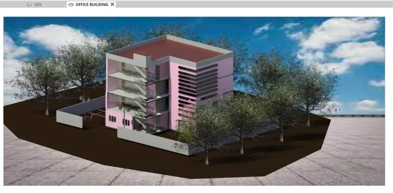
-Go to view>Select sheet>Select std sheet metric>Ok
-In project browser go to Rendering, select it which we want to add in sheet drag it in sheet
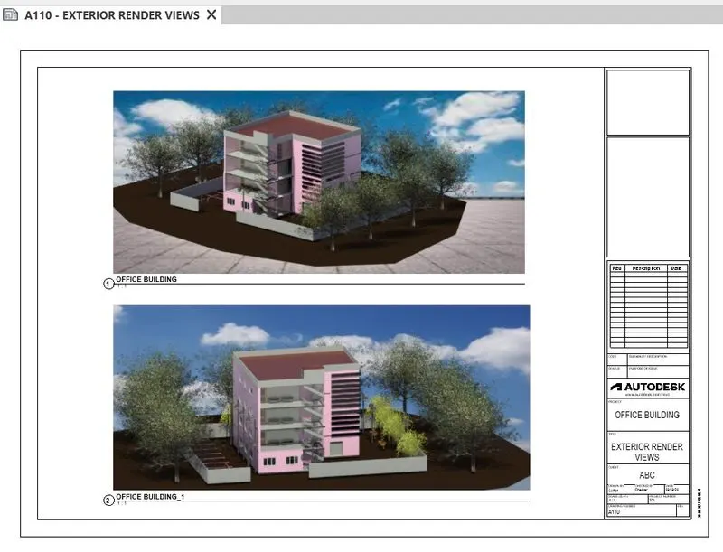
-Follow same procedure to render the views and add in sheet
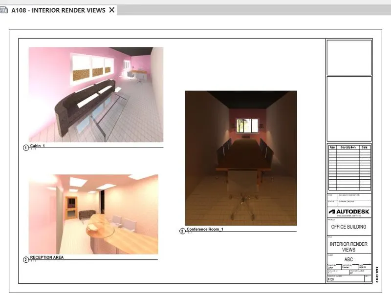
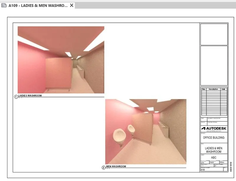
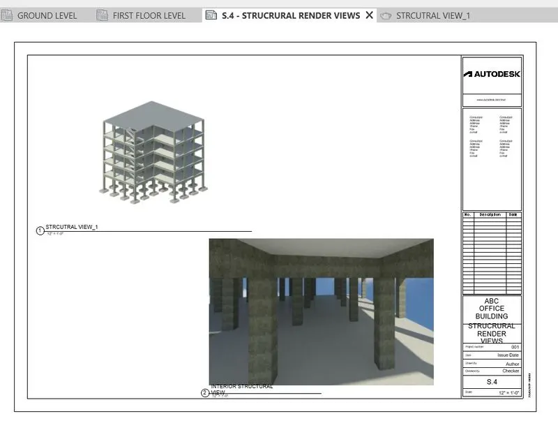
Result-
All the render images are add in sheet.
7]
Aim-To print the set of drawing sheets created and submit the drawing from architecture and structural model.
Introduction-Revit offers different templates for Architectural, Structural, and MEP engineers to work easily based on the preloaded settings in the templates. When we open the Architectural Template, it will consist of both architectural and structural tabs.
The Architectural tab consists of walls, windows, doors, roofs, floors, etc that are used for architectural purposes and modeling whereas the Structural tab consists of structural walls, Columns Beams other Structural elements used for analysis.
Procedure-
-Open the required sheet to print>Press CTRL + P on the keyboard
Print Setup dialogue box opens
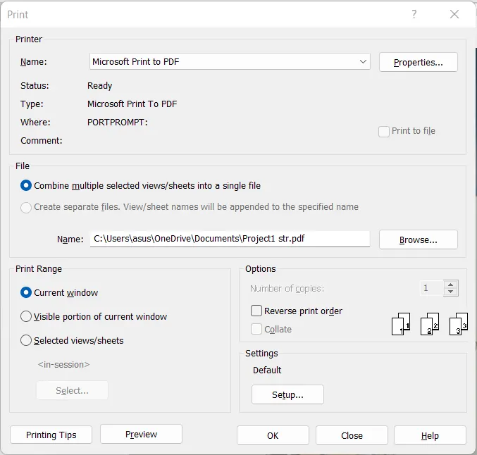
-Set the Print Name>File type,Print Range,Options
-Click on Setup settings option for page setup
-Print Setup dialogue box opens
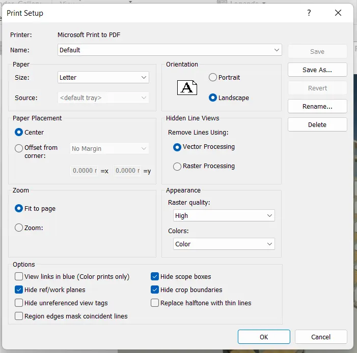
-Set the Paper size,Orientation,Paper placement,Zoom settings,Appearance Settings
-Press OK
-Save the file at the required destination
Result-
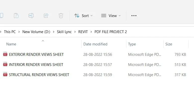
All the sheets are converted to pdf file and submitted it.