Creating Architectural and Structural model with 3D rendering using REVIT
1.
ANS :-From the given structures i want to make a muti-unit REsidential unit.
2)Assume reasonable assumptions for geographic and location details for your project modeling. Based on assumptions and type of structure selected identify the modeling requirements from NBC
ANS:-The ggeographic and location details for your project modeling. Based on assumptions and type of structure selected identify the modeling requirements from NBC are:-
a.As above mentioned by the buildingcomes under the residential category and it can be situated in center of city
b. The project is located in the highway nearest.
c.The road width of project is 60 feet
d. The height ,area limitation and safety measure are followed by NBC 2005
e. The height of project is 42'
f.The project height in meter is 12.8m and road width is 18.2m, so the height of building should not exceed 1.5 times the width of road.
g.In case of building height is not exceed so it is suitable for construction.
3 AIM:- Using the structural model, include the following components based on the type of structure selected
a. Foundation – Isolated / Wall/Matt Foundation
b. Columns
c. Beams Connected to Columns
d. Roof Framing/ Truss
e. Floor / Decks
f. Floor Openings for Elevators and Stairs
COMMANDS USED:-
- ARCHITECTURAL TEMPLATE
- Structural template
- Grids'
- columns
- beams
- foundation
- stAIRS
- SHaft
- floor
PROCEDURE:-
1 AIM:- Open an architectural template. Using the Manage tab set project base point and project shared coordinates for the project
PROCEDURE:- to create project shared coordinates
- OPEN Architectural tab
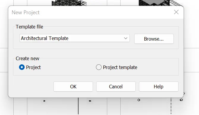
STEP-2:- FIRST save the file with appropriate name
- Go to collabration and enable collabration within your network
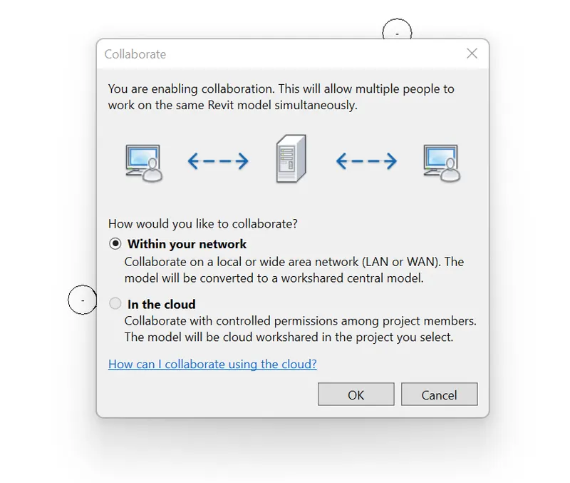
STEP-3:- OPEN MANAGE TAB
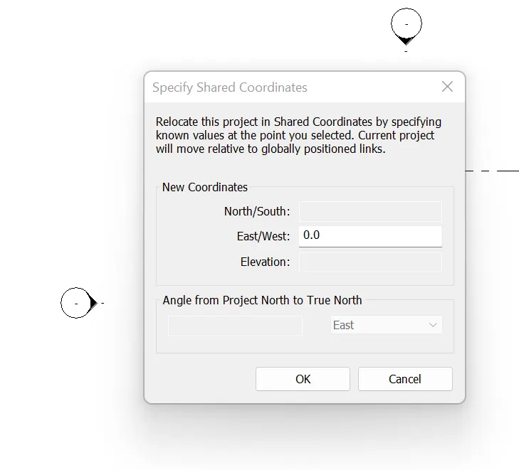
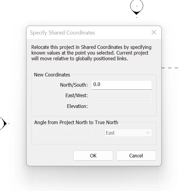
- CLick on project coordinates and then specify shared coordinates
- In east / west type 0'0"
- IN north/south type 0'0"
STEP-4;- go TO architectural tab
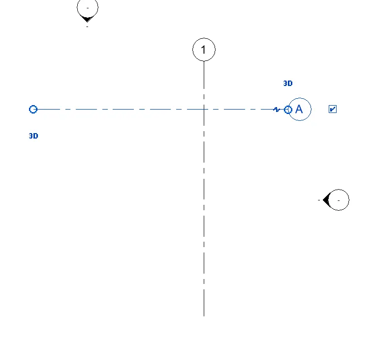
- CLick architectural horizontal and vertical grids
- REANME THE GRIDS
- select manage tab and specify coordinate at point and specify both grids and select 0'0"
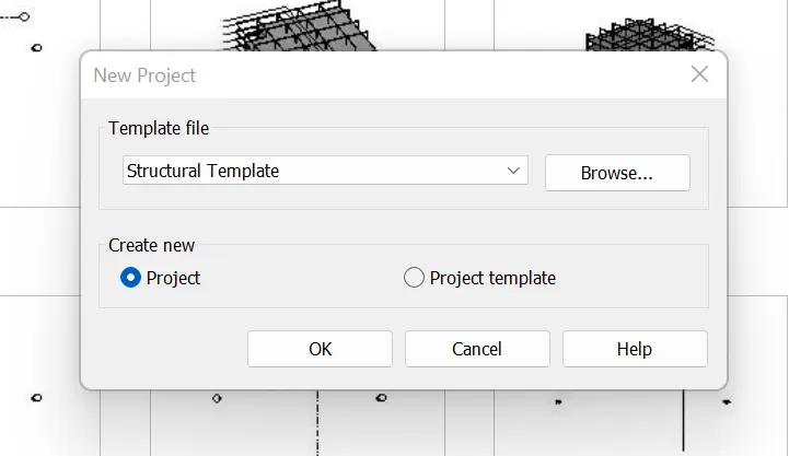
STEP -5:- Open another new file but with a structural template.
to create project shared coordinates
- OPENstructurall tab
STEP-6:- FIRST save the file with appropriate name
- Go to collabration and enable collabration within your network
STEP-7:- OPEN MANAGE TAB
- CLick on project coordinates and then specify shared coordinates
- In east / west type 0'0"
- IN north/south type 0'0"
STEP-8;- go TO architectural tab
- CLick architectural horizontal and vertical grids
- REANME THE GRIDS
- select manage tab and specify coordinate at point and specify both grids and select 0'0"
STEP-9 :-open the architectural template and select manage tab
- IN the manage tab selcet manage links
- SElect the structural dtrawwing
- Both the grids will appear in the drawi ng
- IT is not coinciding
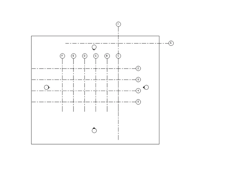
STEP _10:- SELCT the arch grid and acqire coordinate
- Select the position grid and click relocate position
- Selevct the intersection point of the grids
- The grids will be positioned
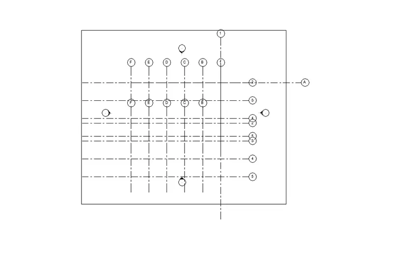
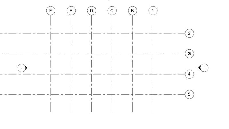
STEP 11 :-
- Now start drawing the structural components of project in structural template
- Draw the vertical and horizontal grid lines ,also set the levels
STEP -12 :-
- DRAW the columns at ground and first floor
- draw foundations also at the bottom of ground floor
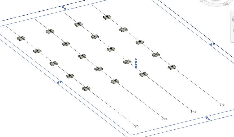
STEP-13:-
- REPeat the same procees and copy columns to above floors
- draw beams also and copy and paste it to levels above
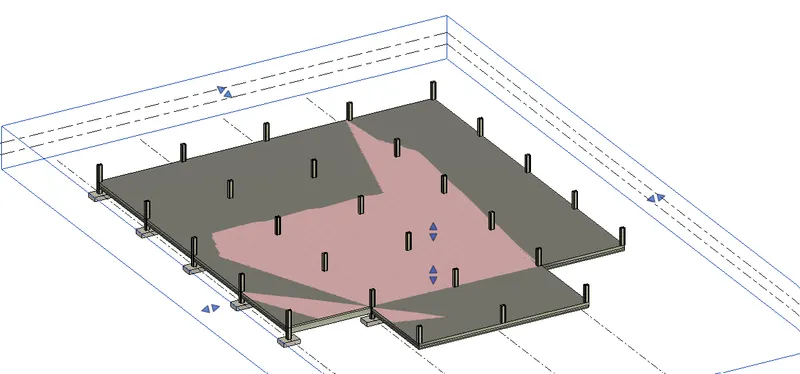
STEP-14:-
- structural model is drawn and save it as a central file
- shafts are also drawn
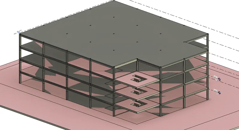
RESULT:-
4. AIM:-Using the architectural model, include the following components based on the type of structure selected
a. Wall Layout with appropriate material and finishing
b. Exterior façade with fancy finish
c. Interior partition walls to size rooms
d. Components to add details to a room ( Desk, Chair, Lighting, Plumbing fixtures)
e. Add components such as stairs Elevators
f. Have at-least one side of the building with curtain walls and glass panels
g. Include interior and exterior lighting fixtures
h. Place proper topographic components from outside ( Trees, Parking, Plants) to add details to the model
COMMAND USED:-
- ARCHITECTURAL TEMPLATE
- Structural template
- Grids'
- columns
- beams
- foundation
- stAIRS
- SHaft
- floor
PROCEDURE;-
- Now go to architectural template which has created before in the file
- Copy the grids which were created before in this file
- With the help from the clipboard option paste the grids in architectural template
- Select the grids and pin it
- click the elevation and create the levels req from architectural template
- Click virtural graphics setting and create the levels
- Now start creating the architectural walls
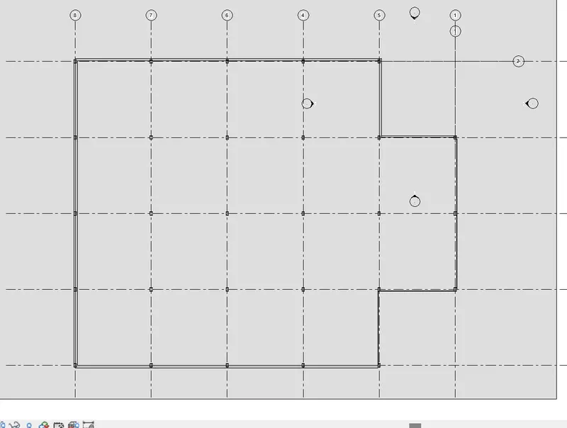
STEP -2 :-now create the exterial wall on grid lines
- Than floor tool add fllor to all levels of project
- Add windows, doors and to walls
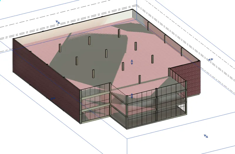
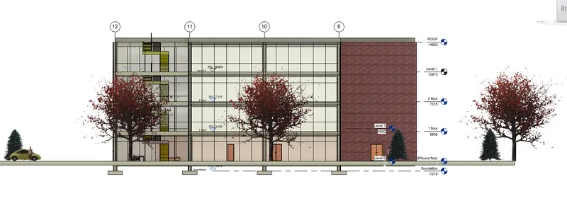
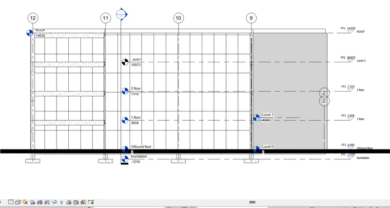
STEP-3 ELEVATion view is visiblle from north
STEP -4
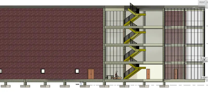
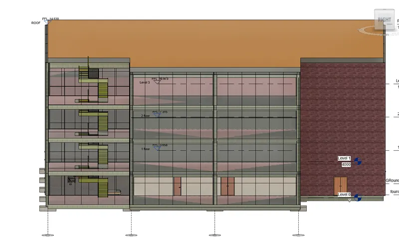
- . Added components such as stairs Elevators
- placed one side of the building with curtain walls and glass panels
- Included interior and exterior lighting fixtures
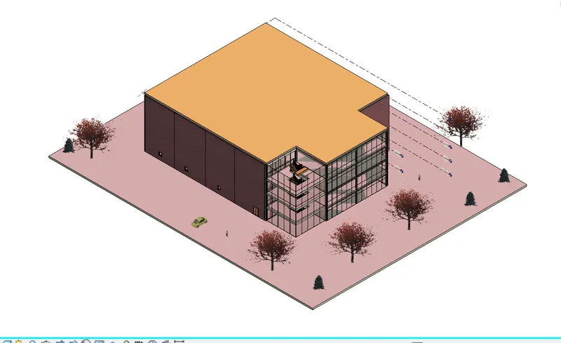
- Placed proper topographic components from outside ( Trees, Parking, Plants) to add details to the model
5 AIM:- Provide a set of drawings in an architectural and structural model to list the following details with categories and appropriate sheet templates included
a. Floor Plans with Annotations
b. Elevations
c. Sections
COMMAND USED:-
- ARCHITECTURAL TEMPLATE
- Structural template
- Grids'
- columns
- beams
- foundation
- stAIRS
- SHaft
- floor
PROCEDURE;-
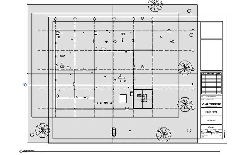
STEp-1:- MAking the ground floor ,1 and other floor plans
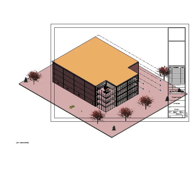
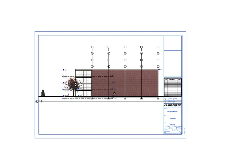
STEP-2 :- ELEVATION VIEW from north is visible
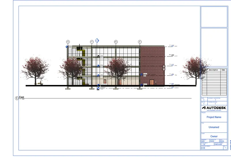
STEP-3 :- OTher elevation views are also drawn
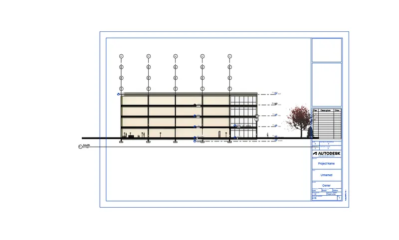
STEP-4 :- elevation view from the south is also avaiablre
STEP-5 SECTIONAL VIEW IS also there
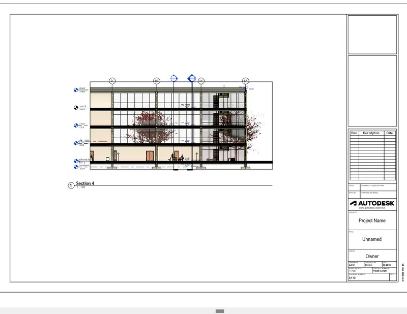
STEp-6:- Sectional view transversely is also there
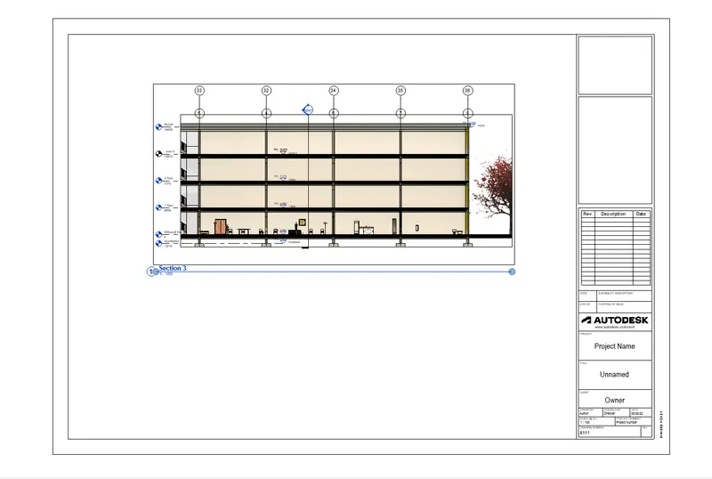
6.AIM:- Using the Rendering settings, Render images of the 3D model produced and include the rendered images to the drawing sheets
a. Rendering from interior rooms
b. Rendering from out showing topographic features
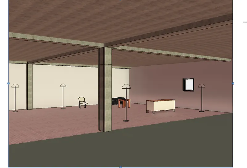
c. Rendering through structural framing
COmmand used :-
- ARCHITECTURAL TEMPLATE
- Structural template
- Grids'
- columns
- beams
- foundation
- stAIRS
- SHaft
- floor
PROCEDURE:-
- Open the 3d view and set view to take the picture where we want to render the area
- click view menu and click render option
- render dialog box appears
- select region option and crop the image in region
- than we change the styles of render images ,schemes ,lightening optionsa and finally click render it
- then the render image will apear in more realisticthan other it can be used to better presenation of oure clients
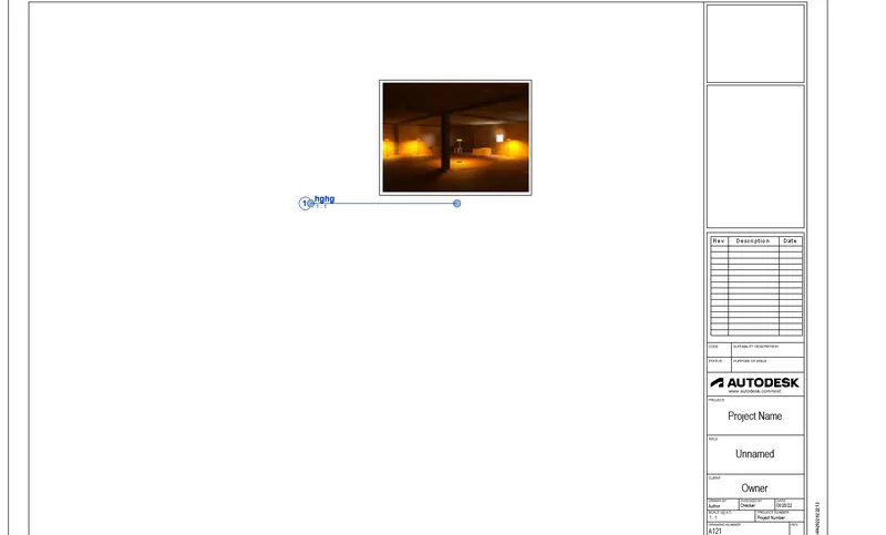
STEP-1:- RENDER image of living room
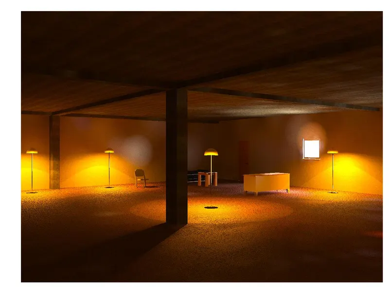
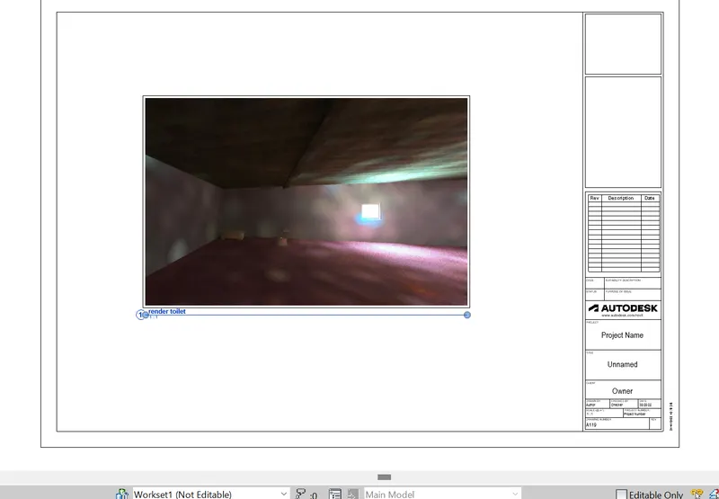
STEP -2 :-render image of washroom
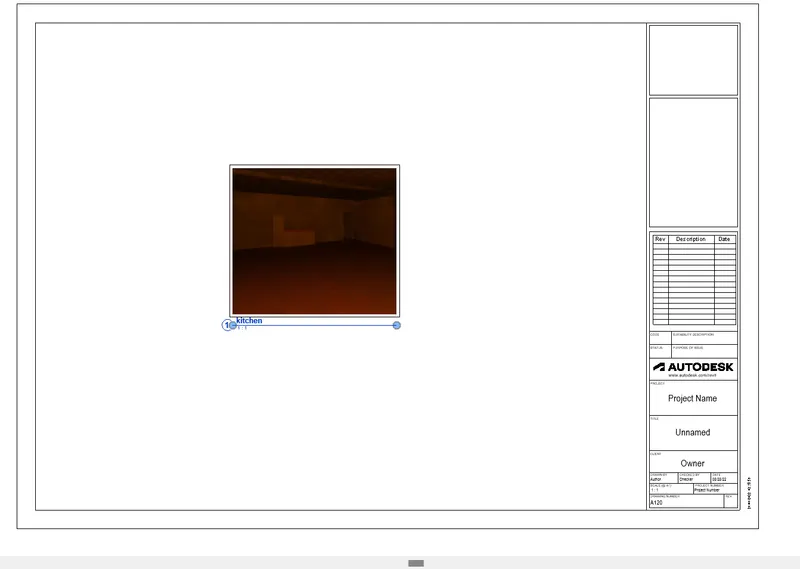
STEP-3 RENDER image of kitchen
\
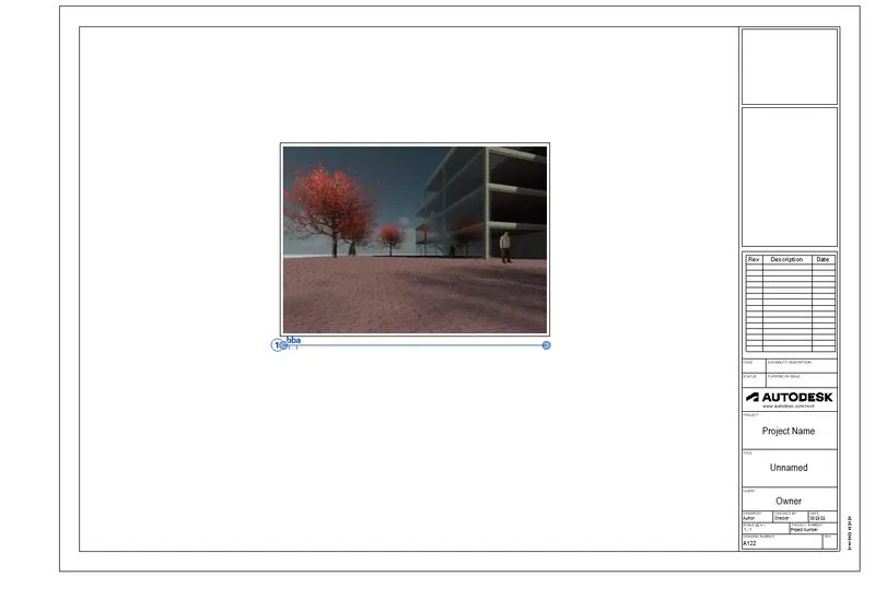
RENDER IMAGE OF building from outside
7. AIM:- Print the set of drawing sheets created and submit the drawings from the architecture and structure model
PROCEDURE :- open the printer
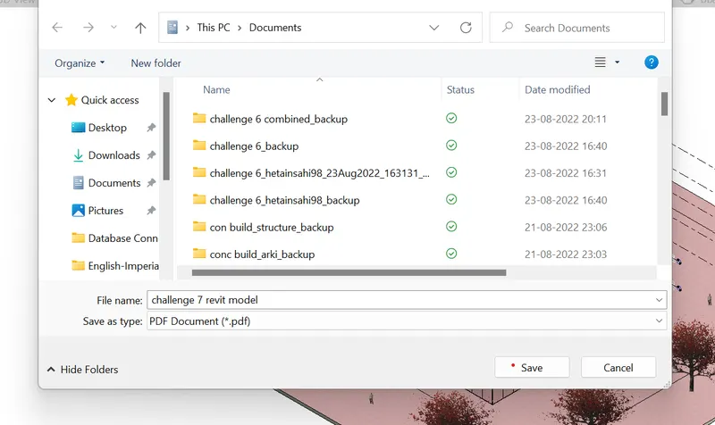
- now change the files from microsoft print to pdf
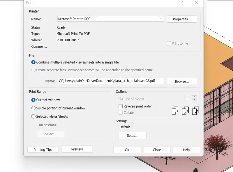
STEP -2 NOW Save the files with name