Creating a Floor plan, Footing detail and Isometric view using AutoCad
1 Aim:- To draw Cross section of load bearing wall over spread footing
Introduction:-The cross section of load bearing wall over spread footing using auto cad is created by lines.
- The proceddure and result should be written after creating the cross section of isolated footing
Procedure:-Open the auto cad software and start using drawing tab
- In command box use line command and give start point as (1,1)
- Than in line command give coordinates as @0.9,0
- Than in line command give coordinates as @0,0.25
- Than in line command give coordinates as @-0.2,0
- Than in line command give coordinates as @0,0.4
- Than in line command give coordinates as @0..5,0
- Than in line command give coordinates as @0.9,0
- Than in line command give coordinates as @0.3
- Than in line command give coordinates as @0.9,0
- Than in line command give coordinates as @0.5,2
- Than in line command give coordinates as @0.9,2
- Than in line command give coordinates as @0.3
- Than in line command give coordinates as @0.9,0
- Than in line command give coordinates as @0.5,2
- Than in line command give coordinates as @0.9,2
- ommand give coordinates as @0,0.25
- Than in line command give coordinates as @-0.2,0
- Than in line command give coordinates as @0,0.4
- Than in line command give coordinates as @0..5,0
- Than in line command give coordinates as @0.9,0
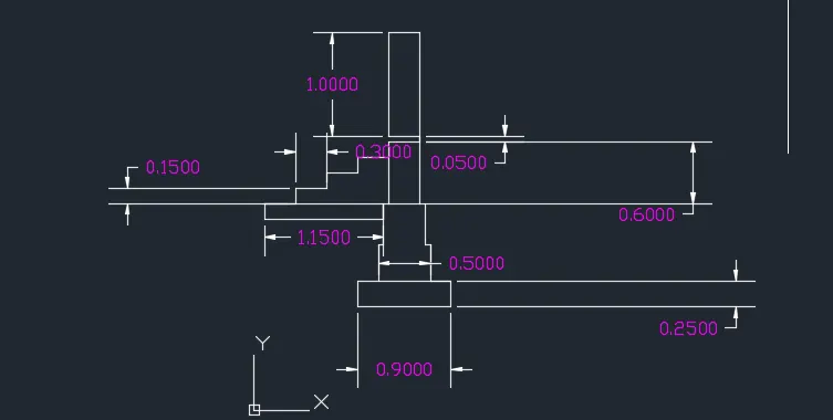
Result:-Cross section of load bearing wall over spread footing is created by lines using autocad
2 Aim:- To draw cross section of isolated footing using autocad
Introduction:-The cross section of isolated footing using auto cad is created by lines.
- The procedure and result should be written after creating the cross section of isolated footing
Procedure:-Open the auto cad software and start using drawing tab
In command box use line command and give start point as (1,1)
- Than in line command give coordinates as @0.9,0
- Than in line command give coordinates as @0,0.25
- Than in line command give coordinates as @-0.2,0
- Than in line command give coordinates as @0,0.4
- Than in line command give coordinates as @0..5,0
- Than in line command give coordinates as @0.9,0
- Than in line command give coordinates as @0.3
- Than in line command give coordinates as @0.9,0
- Than in line command give coordinates as @0.5,2
- Than in line command give coordinates as @0.9,2
- ommand give coordinates as @0,0.25
- Than in line command give coordinates as @-0.2,0
- Than in line command give coordinates as @0,0.4
- Than in line command give coordinates as @0..5,0
- Than in line command give coordinates as @0.9,0
- ommand give coordinates as @0,0.25
- Than in line command give coordinates as @-0.2,0
- Than in line command give coordinates as @0,0.4
- Than in line command give coordinates as @0..5,0
- Than in line command give coordinates as @0.9,0
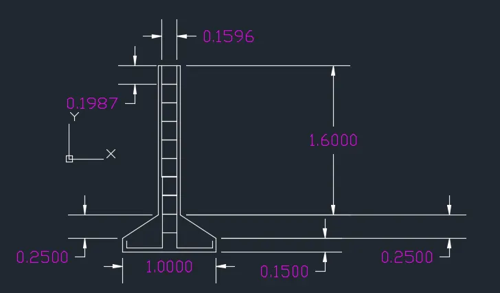
Result:-Cross section of load bearing wall over spread footing is created by lines using autocad
3 Aim:- To draw a line diagram of two bedroom building
Introduction:-The line diagram of 2 bedroom building using autocad is created by lines and rectangle command.The procedure is writeen and results are written
Procedure:-In command box use line command and give start point as (1,1)
- Than in line command give coordinates as @0.9,0
- Than in line command give coordinates as @0,0.25
- Than in line command give coordinates as @-0.2,0
- Than in line command give coordinates as @0,0.4
- Than in line command give coordinates as @0..5,0
- Than in line command give coordinates as @0.9,0
- Than in line command give coordinates as @0.3
- Than in line command give coordinates as @0.9,0
- Than in line command give coordinates as @0.5,2
- Than in line command give coordinates as @0.9,2
- ommand give coordinates as @0,0.25
- Than in line command give coordinates as @-0.2,0
- Than in line command give coordinates as @0,0.4
- Than in line command give coordinates as @0..5,0
- Than in line command give coordinates as @0.9,0
- ommand give coordinates as @0,0.25
- Than in line command give coordinates as @-0.2,0
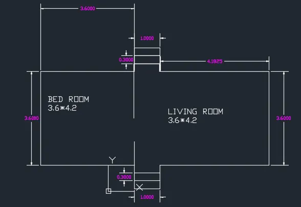
Result: line diagram of two bedroom building is created using auto cad
4 Aim:-To draw Cross section of load bearing wall ahowing foundation details
Introduction:-The cross section of load bearing wall using auto cad is created by lines.
- The proceddure and result should be written after creating the cross section
PRocedure:-
Open the auto cad software and start using drawing tab
- In command box use line command and give start point as (1,1)
- Than in line command give coordinates as @0.9,0
- Than in line command give coordinates as @0,0.25
- Than in line command give coordinates as @-0.2,0
- Than in line command give coordinates as @0,0.4
- Than in line command give coordinates as @0..5,0
- Than in line command give coordinates as @0.9,0
- Than in line command give coordinates as @0.3
- Than in line command give coordinates as @0.9,0
- Than in line command give coordinates as @0.5,2
- Than in line command give coordinates as @0.9,2
- Than in line command give coordinates as @0.3
- Than in line command give coordinates as @0.9,0
- Than in line command give coordinates as @0.5,2
- Than in line command give coordinates as @0.9,2
- ommand give coordinates as @0,0.25
- Than in line command give coordinates as @-0.2,0
- Than in line command give coordinates as @0,0.
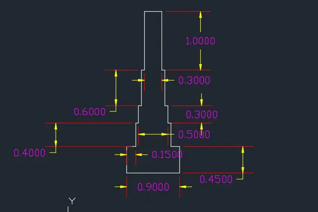
REsult:-Cross section of load bearing wall is created using auto cad
5 Aim:-To draw isometrric view for steps
Introduction:-The isometric view of stairs is done in isometric draft mode by use of lines
- PRocedure:-Put snap on,grid off and isometric snap on
- Ortho on
- Draw a line of 1 unit in x direction
- Draw a line of 0.3 unit in y direction
- Draw a line of 0.5 unit in x direction
- Draw a line of 1 unit in y direction
- Draw a line of 1 unit in x direction
- Draw a line of 0.15unit in x direction
- Draw a line of 1 unit in x direction
- Draw a line of o.3 unit in x direction
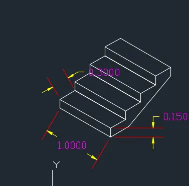
REsult:-Steps are drawn using auto cad
6 Aim:-To draw isometric view of gabble wall
Introduction:-The isometric view of gabble wall is done in isometric draft mode by use of lines
Procedure:-
- -Put snap on,grid off and isometric snap on
- Ortho on
- Draw a line of 1 unit in x direction
- Draw a line of 0.3 unit in y direction
- Draw a line of 0.5 unit in x direction
- Draw a line of 1 unit in y direction
- Draw a line of 1 unit in x direction
- Draw a line of 0.15unit in x direction
- Draw a line of 1 unit in x direction
- Than in line command give coordinates as @0.3
- Than in line command give coordinates as @0.9,0
- Than in line command give coordinates as @0.5,2
- Than in line command give coordinates as @0.9,2
- Than in line command give coordinates as @0.3
- Than in line command give coordinates as @0.9,0
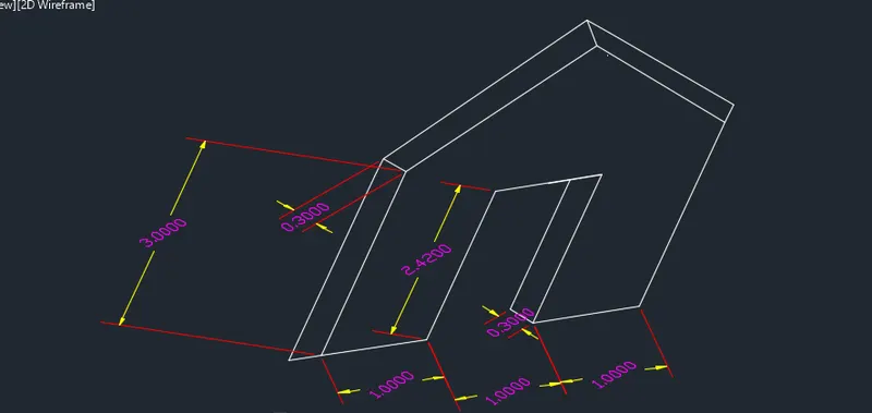
REsult:-Gabble wall is created using auto cad