Creating Architectural and Structural model with 3D rendering using REVIT
1) For this challenge am choosing a) Multi Unit Residential Apartment.
2) My project is loacted at residential area and project is modeling as per NBC rules. The road abutting the building is taken as 9m (30').
3) AIM: To create foundation, columns, beams and roof to the structural model
PROCEDURE:
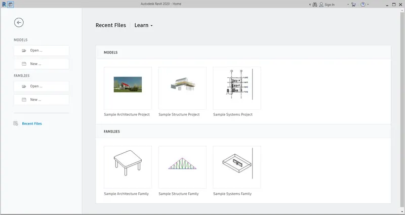
- Go to desktop and select the Revit icon.
- Once the icon the selected then the below shown dialogue box will appear.
- Open the new structural model.
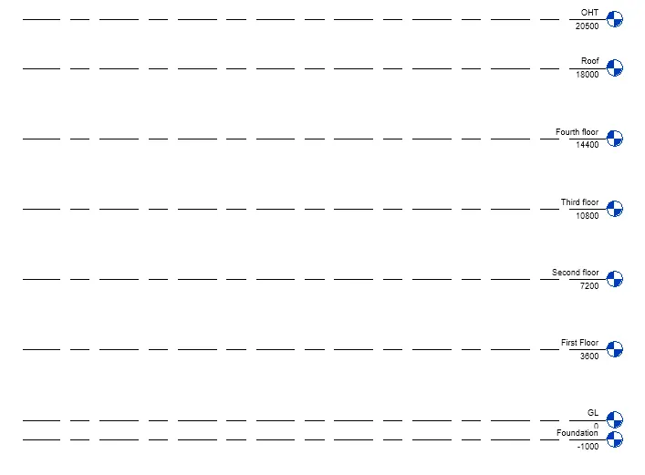
- Go to levels in the architectural option.
- Add or remove the levels as per requirements in the elevation view.
- After adding all te required levels now start with the grid option.
- Place the grid in a state that they are the centre point of the column and anything.
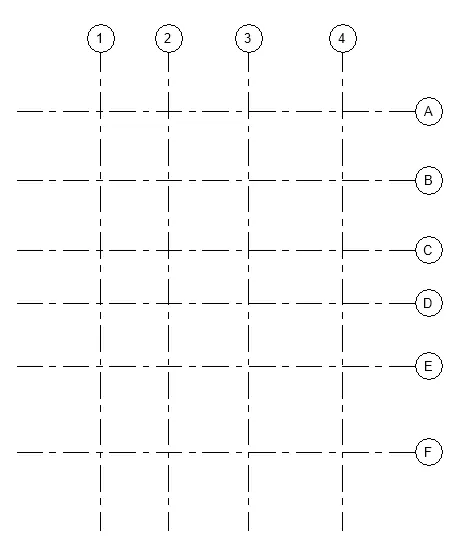
- Once the grids are completed as shown above then start with the foundation work.
- Go to structure menu and select Isolated footing.
- Select load families and insert foundation of required shape.
- Once the selections are done then select the places where thw footing has to be added.
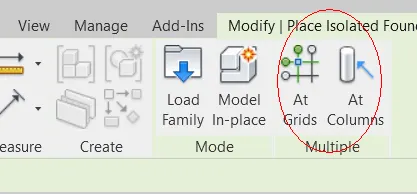
- Here there are two types to add the footing select the requied.
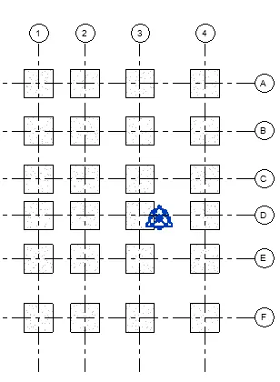
- If all the footings are same then select the At Grids option and go to drawing and select all the grids.
- Then the footing will be appeared in all the intersections.
- Once the footing is completed then start with the column.
- Open structural toolbar, select columns and place them in plan.
- Here we can change all the size and everything as required even the orientation can also be changed.
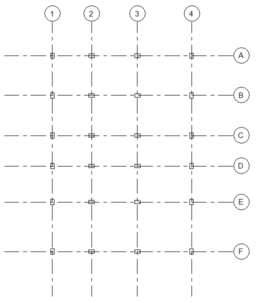
- Rotate the columns as required with respect to the wall conditions and site.
- Once the column and footing are completed now we have to do floor beam and truss.
- So carry the same steps as done for column and footing and complete it.
- So now we will go throught the staircase part.
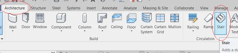
- Select the staircase in the architecture and privide the required dimensions.
- Now click in the starting point of the staircase and next click where the end of staircase needed.
- The number of riser tread all are pre calculated by the software.
- After doing the staircase in one floor then copy and paste it for all the other required floors.
- Now we have to do the floor opening for the elevators and staircase.
- Go to shaft option in architecture option

- Then the below shown options will appear then there select the type and method of doing the shaft and carry on.
- Select the shaft base and end level for accurate shaft.
- If neede then draw the walls in all sides of shaft.
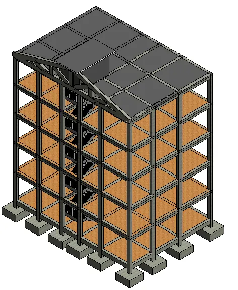
RESULT:
4) AIM: : To create architectural model with appropriate material and finishing.
PROCEDURE:
- Go to desktop and select the Revit icon.
- Once the icon the selected then the below shown dialogue box will appear.
- Open the new Architectural model.
- Go to levels in the architectural option.
- Add or remove the levels as per requirements in the elevation view.
- After adding all te required levels now start with the grid option.
- Place the grid in a state that they are the centre point of the column and anything.
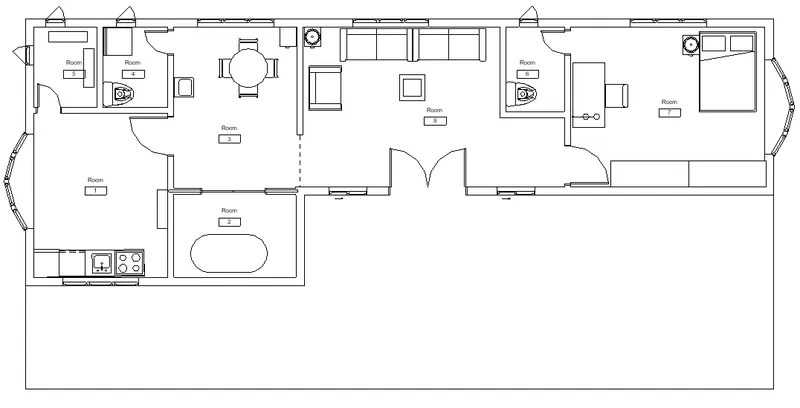
- Once the grids are completed as shown above then start with the walls.
- Follow steps of drawing the wall as shown before.
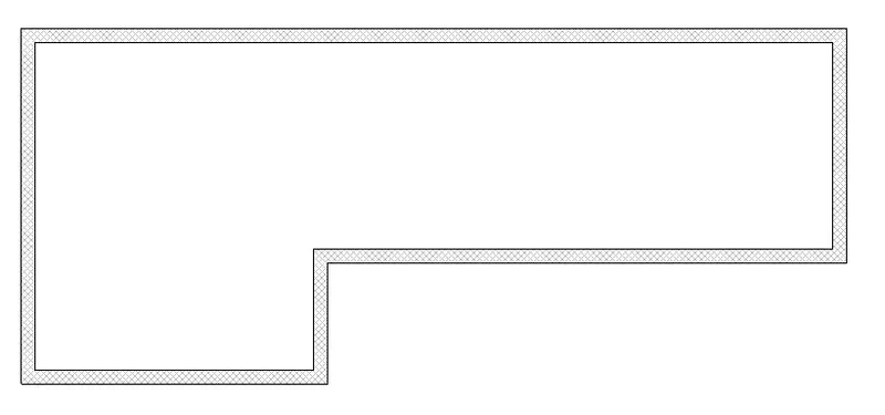
- Once the main outer walls are completed then start with the inner side partition walls.
- Here we have to change the material and size of the wall.
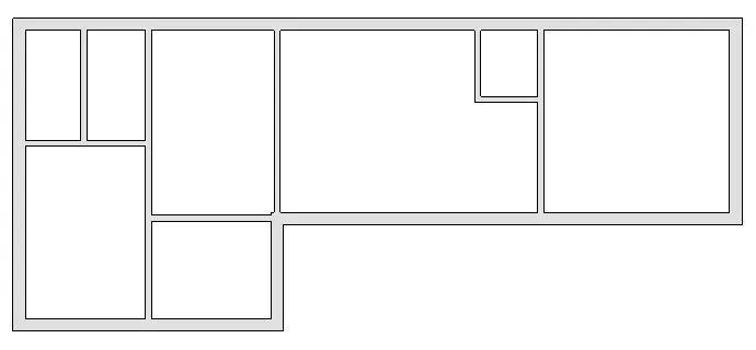
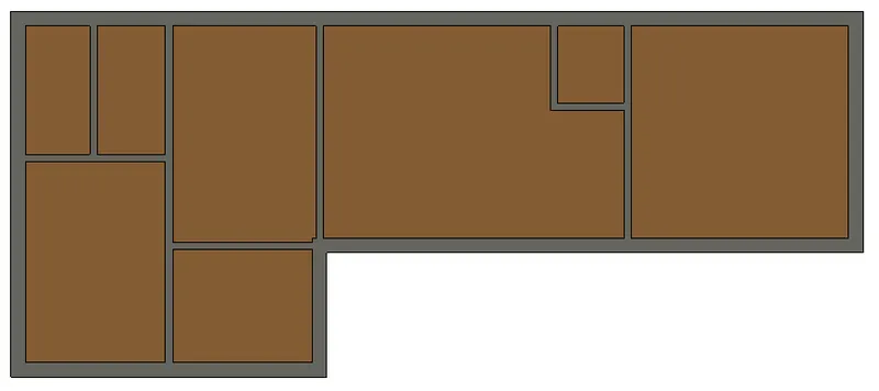
- Once the wall is done then the wall and change the wall material and properties.
- Then start with the Architectural floor give the desire thickness and materials.
- Now place the door and windows as needed.
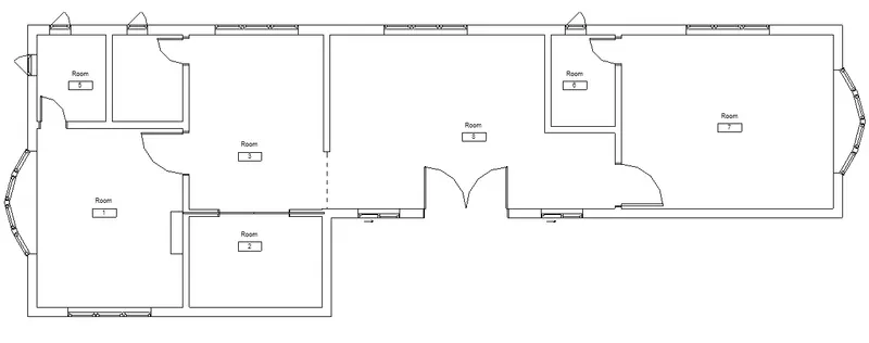
- Place the Desk, Chair, Lighting, Plumbing fixtures etc.
- Place proper topographic components from outside like Trees, Parking, Plants etc.
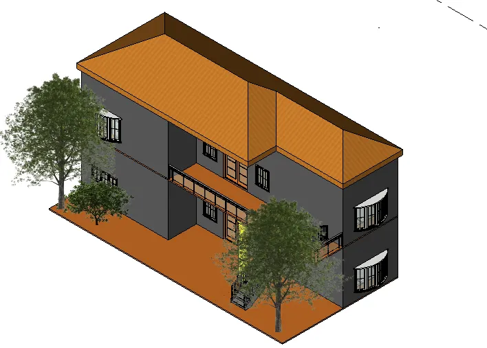
RESULT: Architectural model is created and finishing is completed.
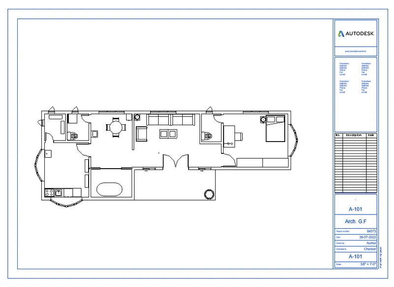
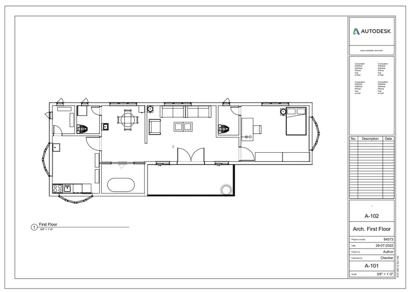
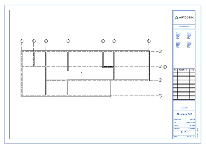
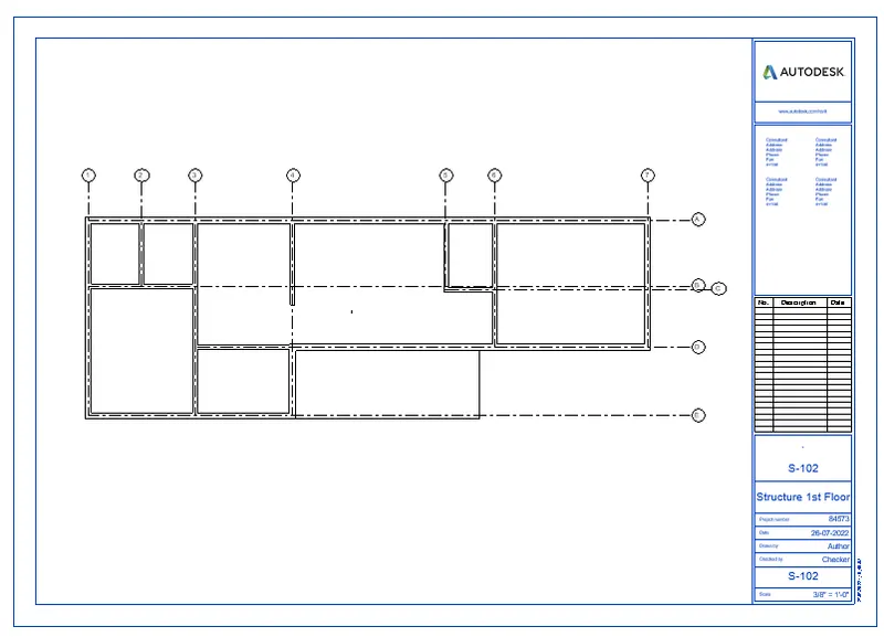
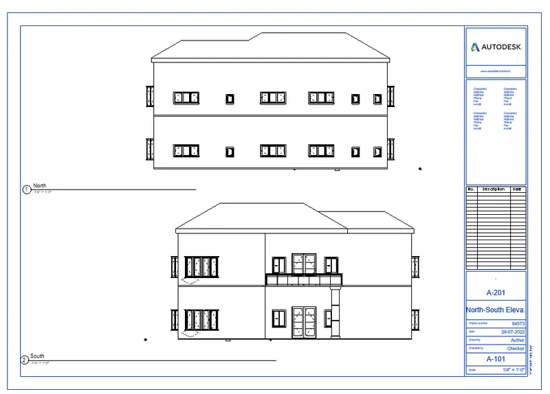
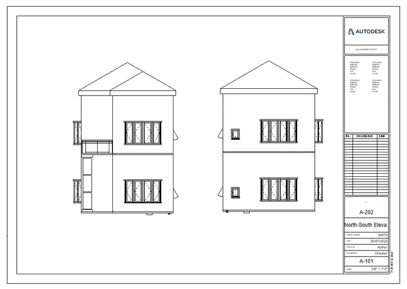
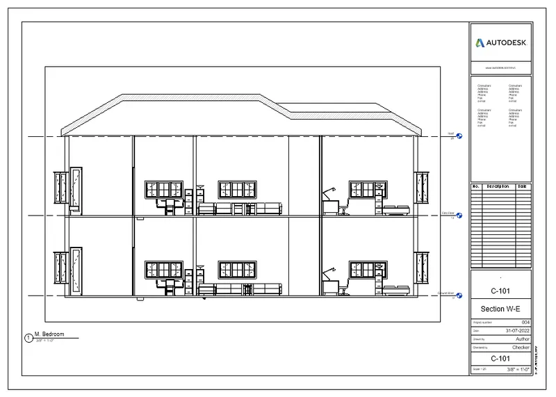
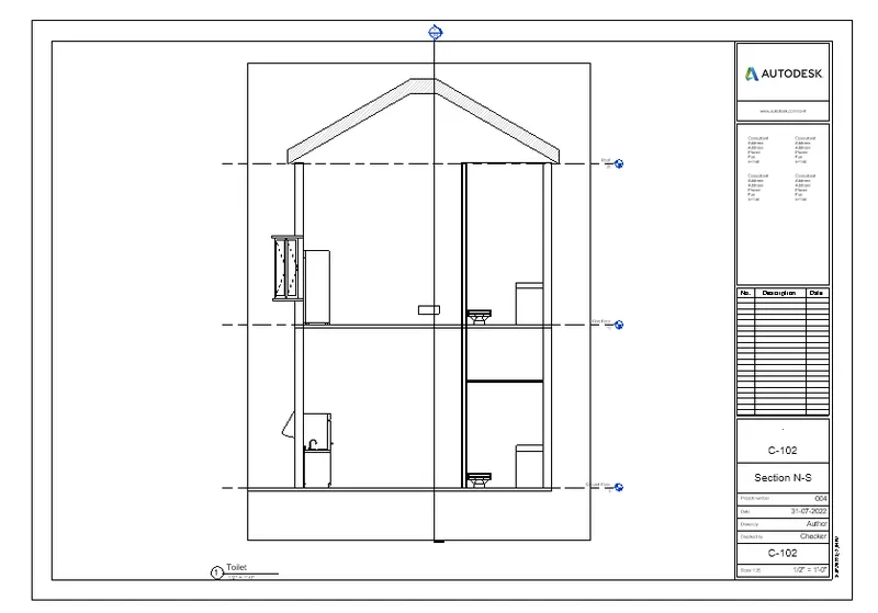
5) AIM: To add floor plan, elevation and section plans to the sheet.
PROCEDURE:
- Go to the drawing from which the sheets has to be done.
- Once the drawing is opened then click on view toolbar and select sheet.
- Now we have to create the sheet as mentioned in the question
- So go to view option in task bar and select the sheet option

- Once you click the sheet option then the below shown dialogue box will appear
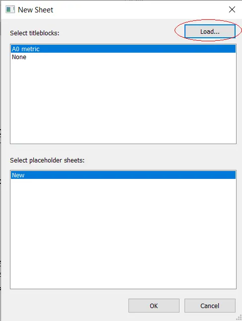
- Once the above box appears now we have to load the sheet we required.
- So press the load option and follow the below steps.
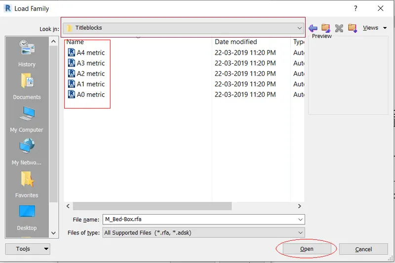
- The above box will appear as soon as we select the load option.
- Here we have to go to the source of sheet like the place where the template are stored.
- Once we go to the designated place now we have have to select the type of sheet required for our drawing.
- Once we have got the required sheet then press open.
- It will be loaded to the New sheet box.
- Once the drawing sheet is visible in the new sheet dialogue box then press okay.
- The selected sheet will appear in the screen.
- Now we have to drag the required view to the sheet from Project Browser.
- After draging the drawing into the sheet set the view scale in teh properties menu.
- Make the drawing fits the sheet properly.
- Carry the same procedure for all the other mentioned drawing sheets.
RESULT:
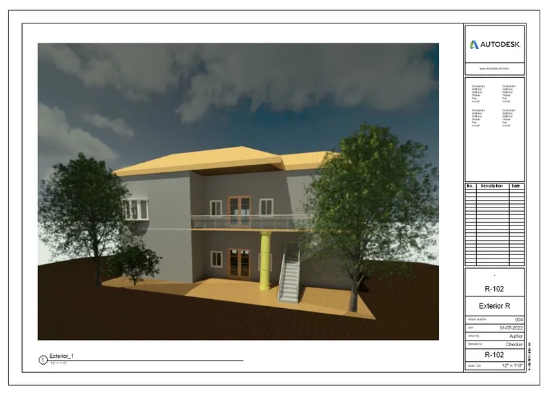
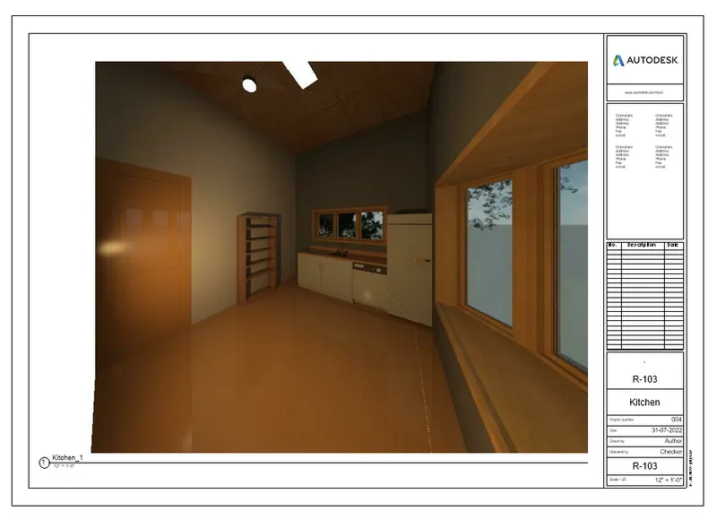
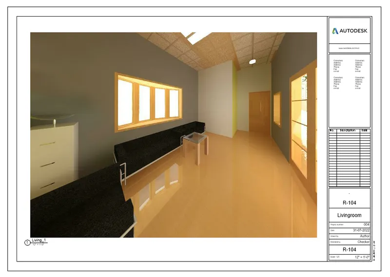
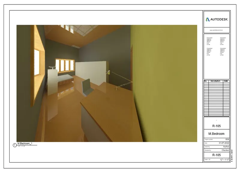
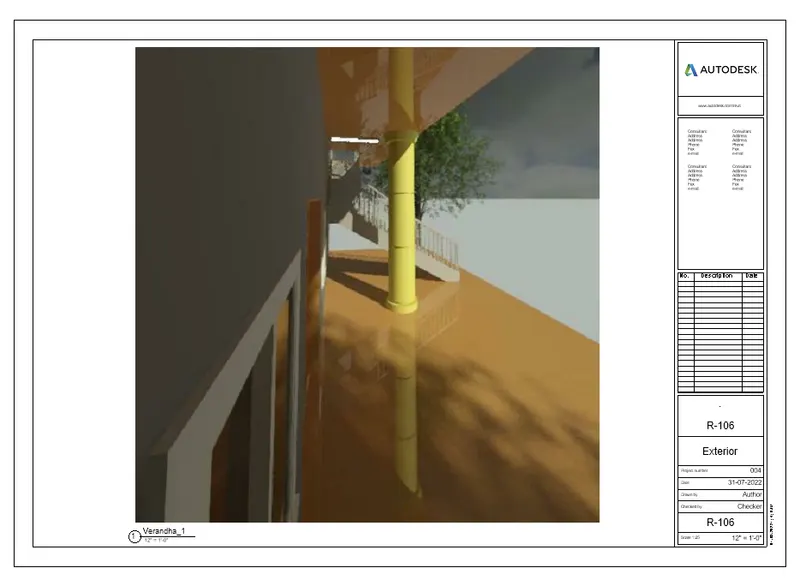
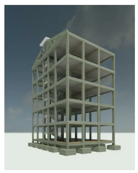
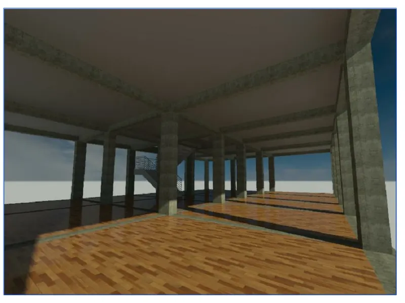
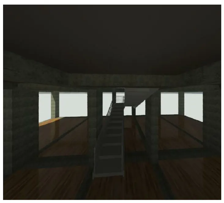
6) AIM: To Render the images of interior rooms, topograhic features and structural framing.
PROCEDURE:
- Go to the drawing from which we can get all the required views.
- Before doing the Rendering views we have to place the cameras so follow the below steps.
- Then go to 3D view and there a drop menu will appear then go to camera there.
-
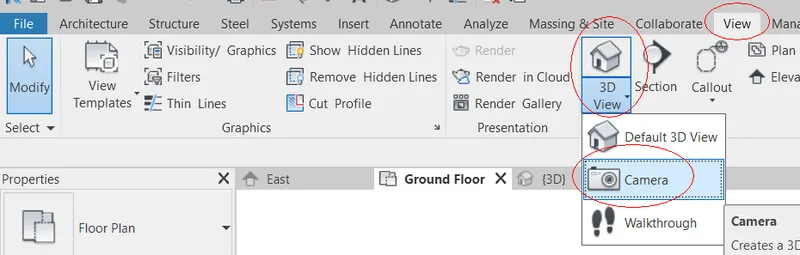
- Then select the place where the camera has to be placed.
- Now there will be 3 lines take that lines to where the camera has to focus or cover.
- Click on the point or place where the camera has to be faced.
- As soon as the cameras are placed the new views will appear in the 3D views.
- Once the cameras are placed then go to view command and select render command.
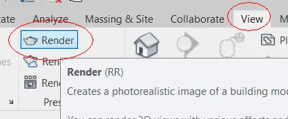
- The below show dialogue box will appear.
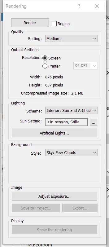
- Here select the type of lighting scheme, Type of background and Quality of rendering etc.
- After all the selections now press render the rendering will start.
- Once the rendering is completed then either we can save the drawing as jpg or in the project.
RESULT:
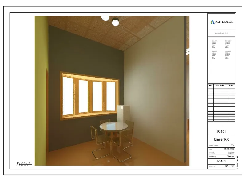
7) AIM: To print the set of drawing sheets created and submit the drawings.
PROCEDURE:
- After completing all the drawin sheet creation now we have to print the sheet.
- Click on print option.
- Click on view or sheet to be printed.
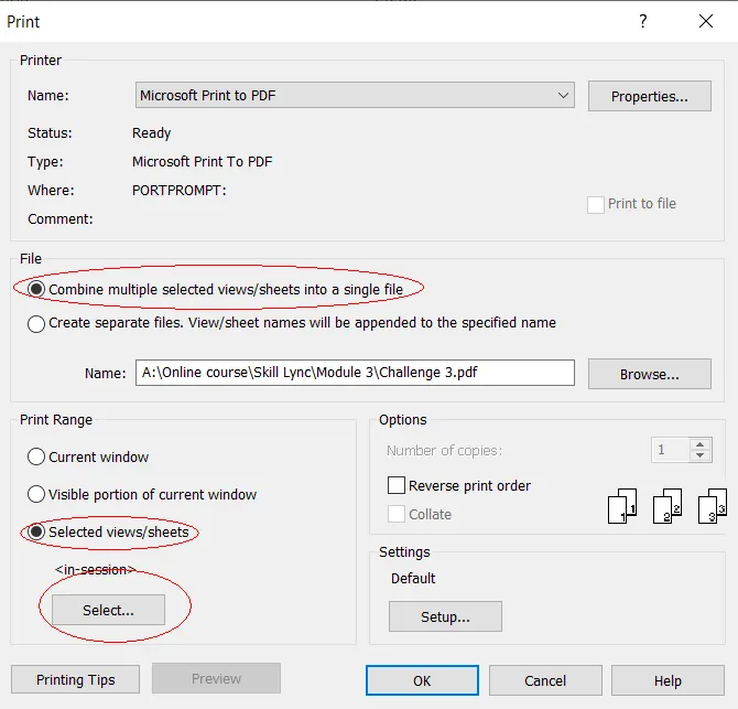
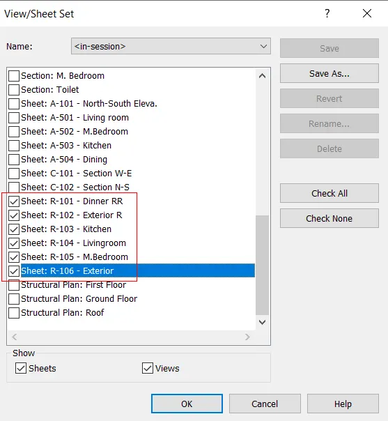
- Select all the sheets that has to be plotted.
- Edit the parameters and click ok.
RESULT:
From above steps ,printing the sheets are possible.