Creating Architectural and Structural model with 3D rendering using REVIT
Question:- 1
Select the type of structure you want to build from one of the three below:
a. Multi-Unit Residential Apartment
b. Office Buildings
c. School
Result :-
- From the above options, I will go with Multi-Unit Residential Apartment.
Question:- 2
Assume reasonable assumptions for geographic and location details for your project modeling. Based on assumptions and type of structure selected identify the modeling requirements from NBC.
Result :-
- As above mentioned by building comes under th eresidential category and it can be suitable in the city area.
- The height, area limitations and safety measure are followed by NBC 2016.
- The height of the building is 45'.
- Width of the road is 18.5m.
- Height of the building is not exceeding 1.5 times width of the road.
- So it is suitable for Construction.
Question:- 3
Using the structural model, include the following components based on the type of structure selected
a. Foundation – Isolated / Wall/Matt Foundation
b. Columns
c. Beams Connected to Columns
d. Roof Framing/ Truss
e. Floor / Decks
f. Floor Openings for Elevators and Stairs
Aim :-
- To use the structural model and include the components used in the Multi-Unit Residential Apartment like Isolated Foundation, Columns, Beams.
Introduction :-
- When you use a structural template as the starting point for a new model, the view properties and ranges are modified to work with structural components.
- Although you can work with structural components in projects based on non-structural templates, you must modify view ranges to display the structural components in the view.
- This is because structural components, such as beams and columns, are placed on the level below the view you are working in. Therefore, they fall below the bottom cut plane of the view range and do not display.
Procedure :-
- Open Revit 2023.
- Choose the tempalate file Architecture Template.
- Manage Tab -> Coordinates -> Specify coordinates at Points.
- Enter the amount 0.
- Now type VG for Visibility Graphics.
- Go to Manage TAb.
- Go to Site option in Model categories.
- Select Project base point.
- Click on the base point circle.
- Insert 0 in all the parameters.
- Save the file as Architectural.
- Open an Structural Template.
- Using the Manage tab set project base point and project shared coordinates for the project as created in the Architectural template.
- Re-open the Architectural model.
- Go to Collaborate tab.
- In Collaborate window, Select the Within your Network Option.
- Click File tab -> Save As (Project).
- Do the same process in structural Model.
- Create another new file with a Architectural template. Save the new file as a central model. This file will include both architectural and structural model. Under the manage tab, Click manage links to link both architectural and structural files.
- After Collaborating both the file, Link the Structural File to the Architectural file.
- Create the local files and start working in the Structural local file.
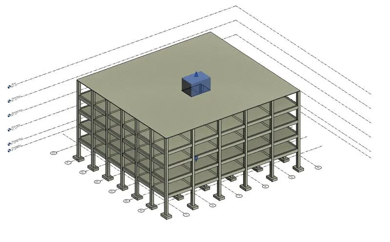
- Create the levels at Foundation, Ground Floor, First Floor, Second Floor, Third Floor, Roof athe disatance of 10'.
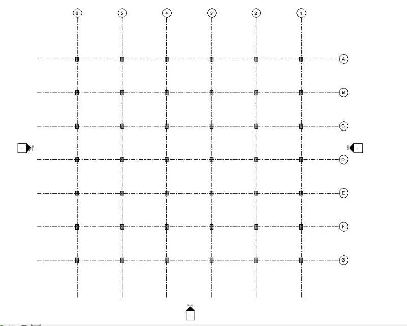
- Create the grids horizontally at the distance of 15'.
- Create the grids vertically at the distance of 20'.
- Name the grids appropriately.
- Now Selct the column and place it at the grids.
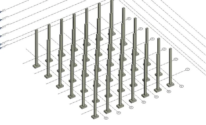
- Now Place the Foundation at the foundation level.
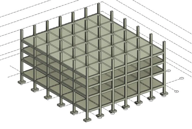
- Now place the Beams and Floors at every floor.
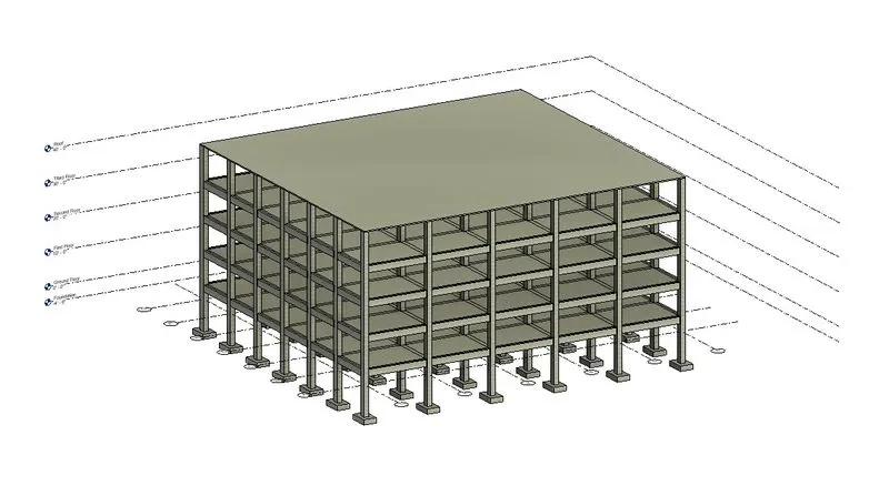
- Place the Roof at the Roof level.
- Now place the Floor Openings for Elevators and Stairs at the center of the building.
Result :-
- We have completed the structural model by placing Foundation – Isolated / Wall/Matt Foundation, Columns, Beams Connected to Columns, Roof Framing/ Truss, Floor / Decks, Floor Openings for Elevators and Stairs.
Question:- 4
Using the architectural model, include the following components based on the type of structure selected
a. Wall Layout with appropriate material and finishing
b. Exterior façade with fancy finish
c. Interior partition walls to size rooms
d. Components to add details to a room ( Desk, Chair, Lighting, Plumbing fixtures)
e. Add components such as stairs Elevators
f. Have at-least one side of the building with curtain walls and glass panels
g. Include interior and exterior lighting fixtures
h. Place proper topographic components from outside ( Trees, Parking, Plants) to add details to the model.
Aim :-
- To Create components based on the type of structure using the architectural model.
Introduction :-
- With this template you will have a completely setup projects with families designed to give you a unique, clean and simple look that puts your design in view.
- By eliminating extra clutter from your views you can concentrate on making important design decisions without any distractions.
- To make the presentation creation easy, this template includes parametric families that are there to help you explain the idea behind the design as well as videos with some tips and tricks on how to get the most out of them.
Procedure :-
- Create the walls around the building in architectural template.
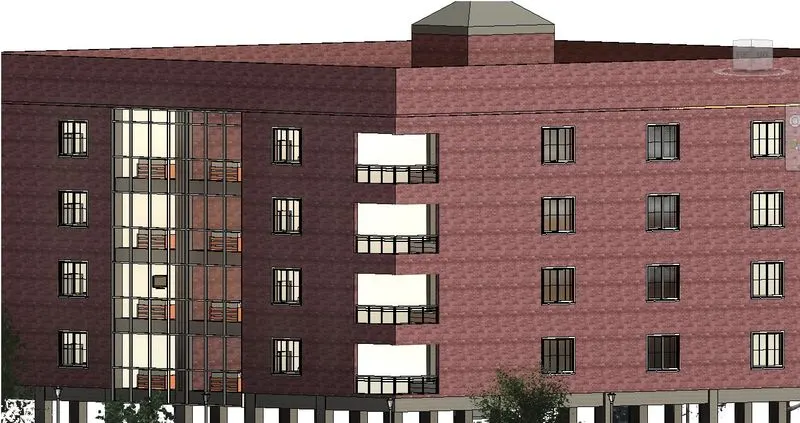
- Place thebalcony at the four corner of the building.
- For that give the wall opening option.
- Place the Curtain wall at the wesa East face of the building.
- Place the components in the building related to architectural aesthetics.
- There are many components are used in the building model like Desk, Chair, Lighting, Plumbing fixtures and many more.
- There are 2 elevators and common Staircase in the building.
- There are interior and exterior lighting fixtures included in the building.
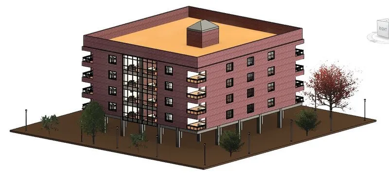
- Placed proper topographic components from outside ( Trees, Parking, Plants) to add details to the model.
Result :-
- Created components based on the type of structure using the architectural model.
Question:- 5
Provide a set of drawings in an architectural and structural model to list the following details with categories and appropriate sheet templates included
a. Floor Plans with Annotations
b. Elevations
c. Sections
Aim :-
- To provide a set of drawings in an architectural and structural model to list the details with categories and appropriate sheet Templates.
Procedure :-
- Create a sheet view for each sheet in the construction document set. You can then place multiple drawings or schedules on each sheet view.
- Place the different type of floor drawings, Elevations, Sections in the sheets.
Result :-
- Provided a set of drawings in an architectural and structural model to list the following details with categories and appropriate sheet templates.
A. Floor Plans with Annotations
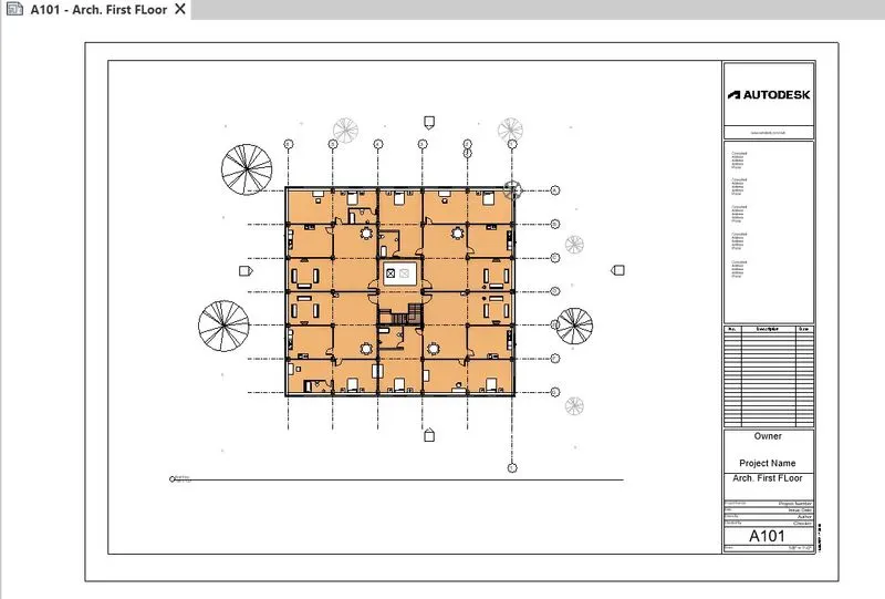
Architecture First Floor Plan
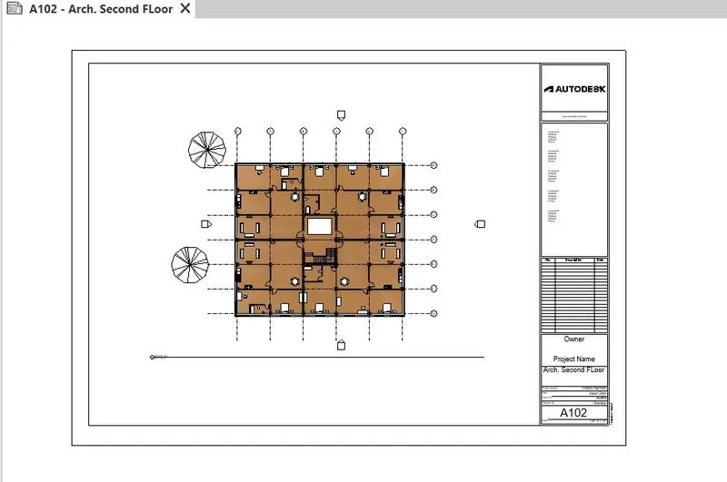
Architecture Second Floor Plan
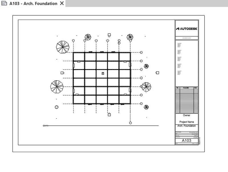
Architecture Foundation Plan
B. Elevations
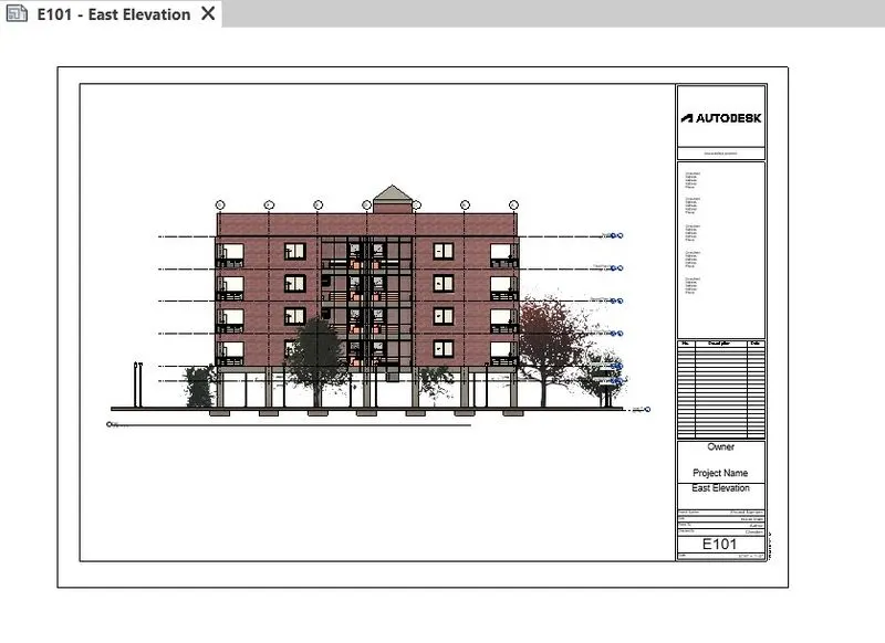
East Elevation
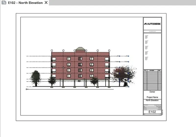
North Elevation
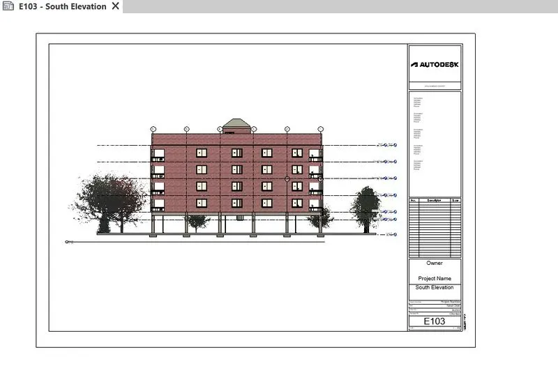
South Elevation
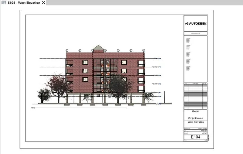
West Elevation
C. Sections
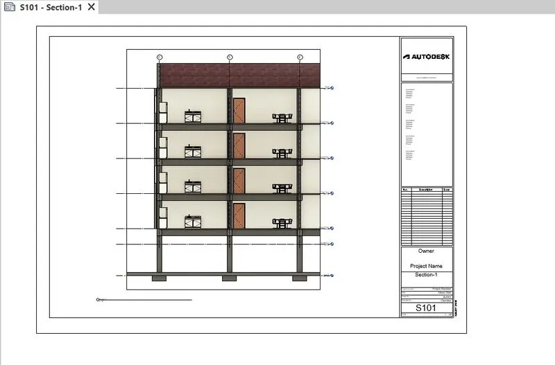
Section-1
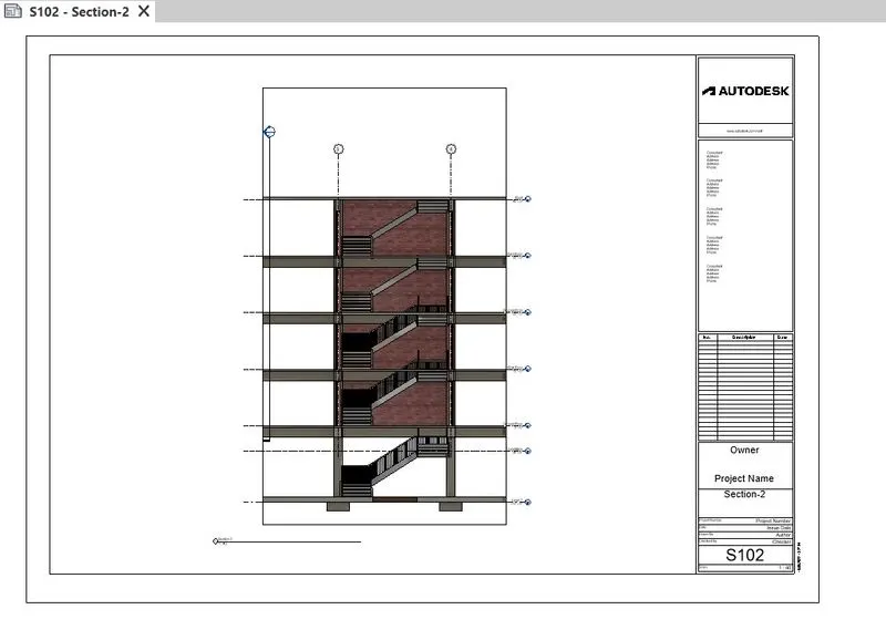
Section-2
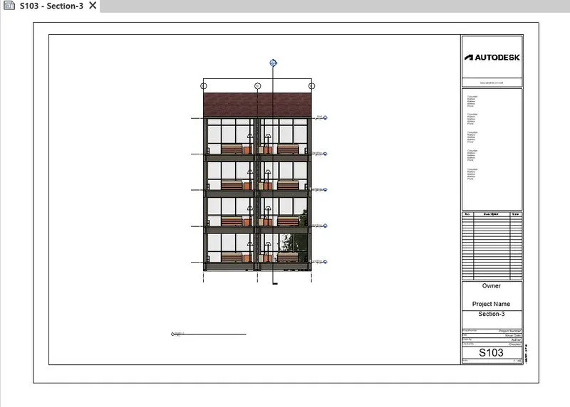
Section-3
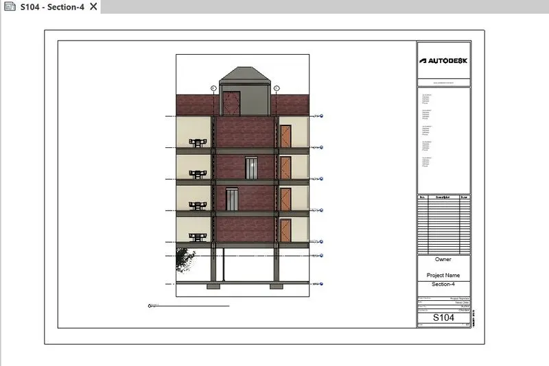
Section-4
Question:- 6
Using the Rendering settings, Render images of the 3D model produced and include the rendered images to the drawing sheets
a. Rendering from interior rooms
b. Rendering from out showing topographic features
c. Rendering through structural framing
Aim :-
- To Render images of the 3D model produced and include the rendered images to the drawing sheets using the Rendering settings.
Introduction :-
- Rendering in Revit is an excellent way to create images that are closer to the real result, because it offers greater details and provides a better understanding of what was set out in the project.
- Rendering is a digital processing of a 3D (three-dimensional) model into a 2D (two-dimensional) image, resulting in an image with a high degree of realism.
- Revit has a native renderer in the program, but it is possible to resort to plugins or other rendering software that can provide very realistic results.
Procedure :-
- With your project's floor plan open, go to the View tab and in the Create panel locate the 3D View button.
- Clicking on the 3D View button you will have access to other options, including the Camera option.
- The camera view will immediately appear and you will be able to use the handles to adjust the framing.
- To render your scene in Revit, just go to the View tab and in the Presentation panel click on the Render button.
- You now have access to the Rendering window where we can make a series of adjustments to the image you are going to render.
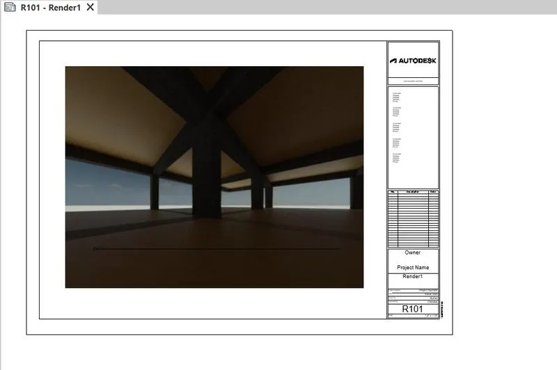
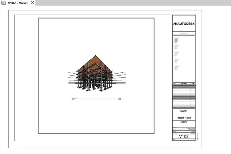
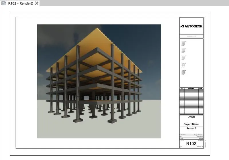
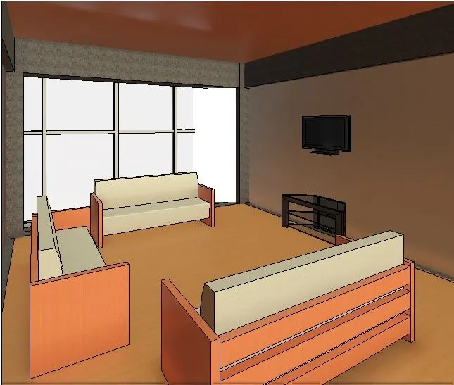
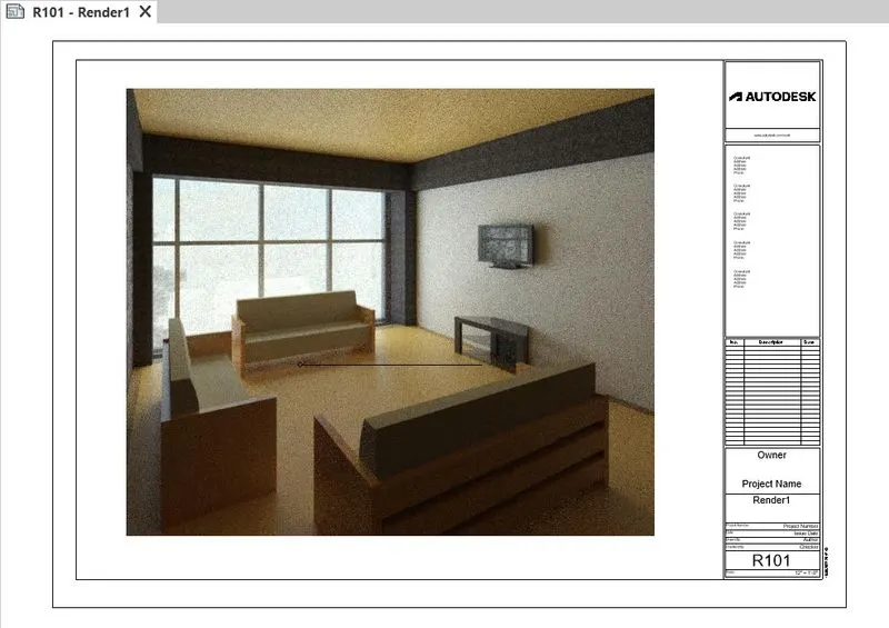
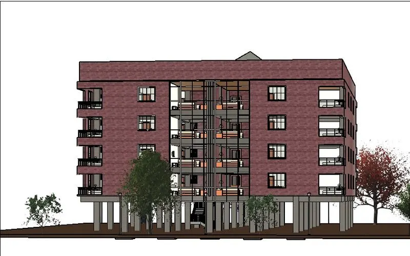
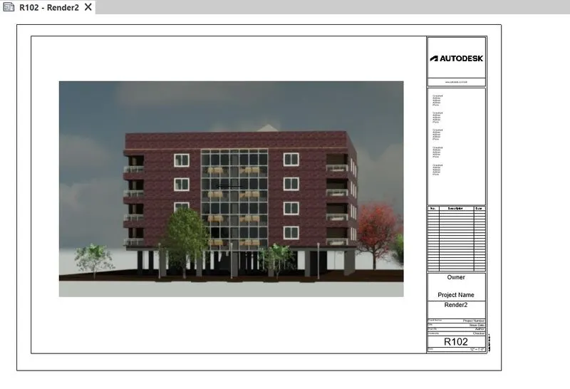
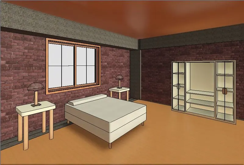
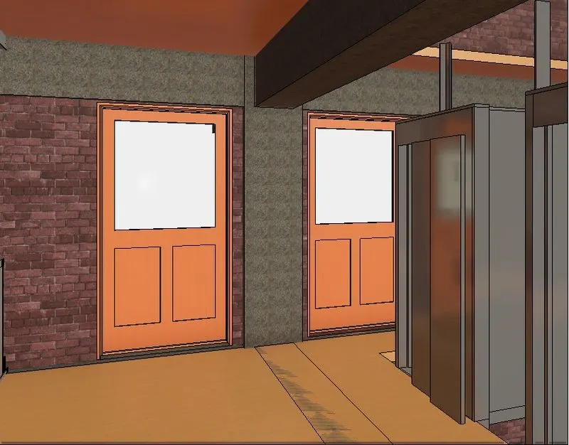
- I have created different views and then rendered that views.
A. Structural Model
View-1 :-
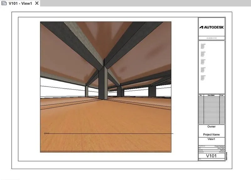
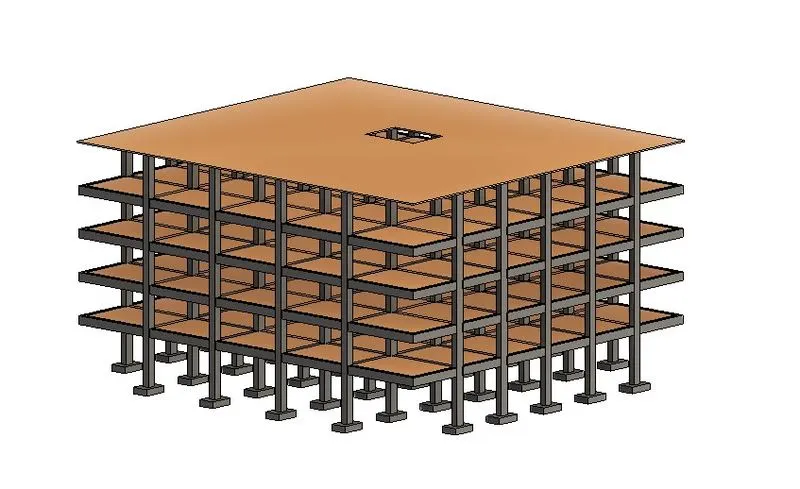
Structural Floor and Columns
Rendered View-1 :-
View-2 :-
Rendered View-2 :-
A. Architectural Model
View-1 :-
Rendered View-1 :-
View-2 :-
Rendered View-2 :-
View-3 :-
Rendered View-3 :-
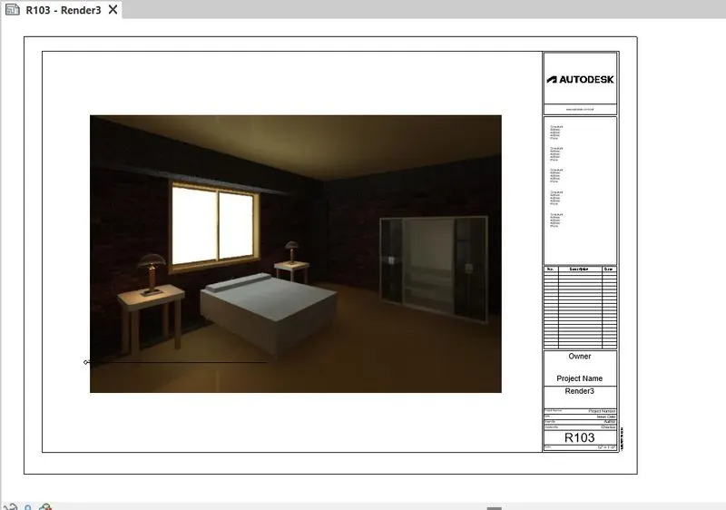
View-4 :-
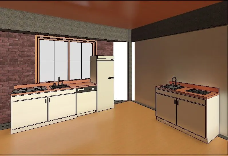
Rendered View-4 :-
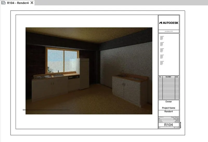
View-5 :-
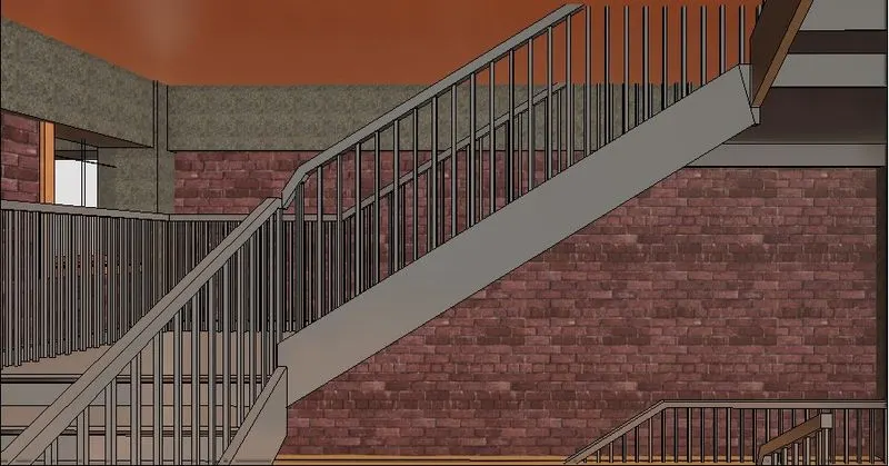
View-6 :-
Result :-
- Rendered images of the 3D model produced and included the rendered images to the drawing sheets using the Rendering settings.
Question:- 7
Print the set of drawing sheets created and submit the drawings from the architecture and structure model.
Aim :-
- To Print the set of drawing sheets created and submit the drawings from the architecture and structure model.
Introduction :-
- Print views and sheets from the current model.
- To streamline the printing process, you can create and save print setups for different type of print jobs. You can also create and save sets of views/sheets, so it is easy to reprint a set later.
Procedure :-
- Click File tab -> Print
- In the Print dialog, for Name, select a printer.
- To print a complete copy of the project before the first page of the next copy is printed, select Collate. To print all copies of the first page and then print all copies of each subsequent page, clear Collate.
- To change print settings, under Settings, click Setup.
- When you are ready to print, click OK.
Result :-
- Printed the set of drawing sheets created and submit the drawings from the architecture and structure model