Creating Architectural and Structural model with 3D rendering using REVIT
1- Select the type of structure you want to build from one of the three below:
- Office building
2- Assume reasonable assumptions for geographic and location details for your project modeling. Based on assumptions and type of structure selected identify the modeling requirements from NBC
- The project is in topographically plain area
- It is in commercial space.
- The road width is 70ft infront of the structure
- An exit must be provided in every building,so as to to permit safe escape of residents in times of fire escape.
- The main staircase and fire escape staircase must be continuous from ground floor to the terrace level.
- The interiors must be constructed with non-combustible material only.
3- AIM - Using the structural model, include the following components based on the type of structure selected
Foundation – Isolated / Wall/Matt Foundation
b. Columns
c. Beams Connected to Columns
d. Roof Framing/ Truss
e. Floor / Decks
f. Floor Openings for Elevators and Stairs.
Procedure –
- First open the Revit software.
- Select new project and structural template.
- Make grids using grid command.
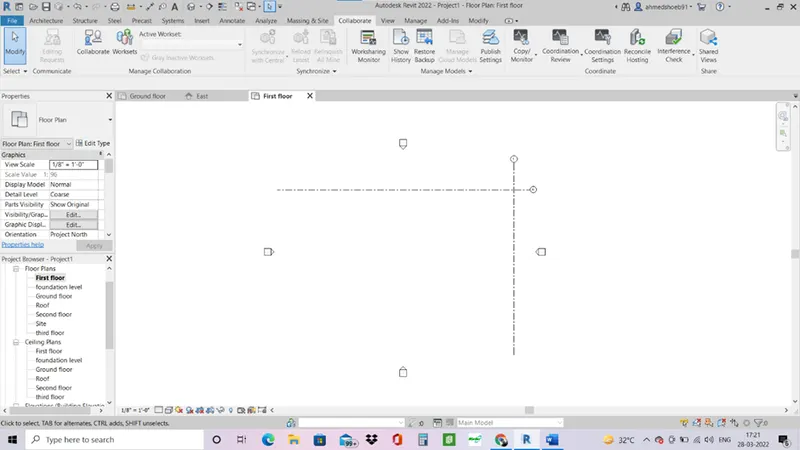
- Go to manage and specify the coordinates at 0,0
- Specify the base project point at 0,0,0. This will set the coordinates at a absolute value.
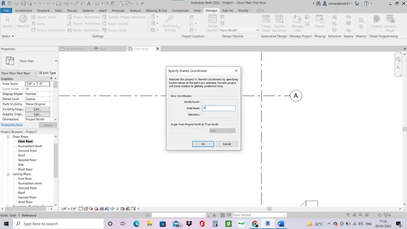
- Now go to elevation and define levels using level command. Define foundation level, ground level, first floor, etc.
- Now go to manage and collaborate the project and save it as central model.
- Go to foundation level, grids are already made according to the structure requirement, so select the footings command in structure, isolated footing and sketch according to the grids. This will make isolated footings on the grids automatically.
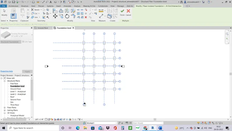
- For column go to columns in structure and select the required column that is to be placed. Set the base constraint as foundation and top constrain as roof.
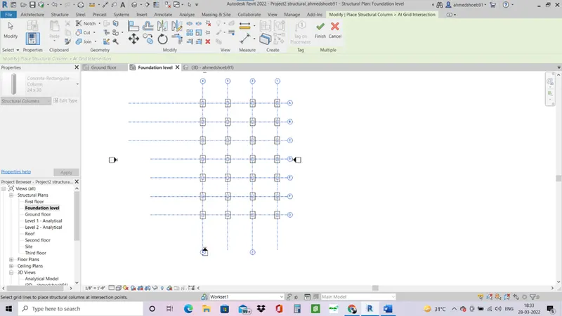
- Select the grids at which grids the columns is to be placed and place it accordingly.
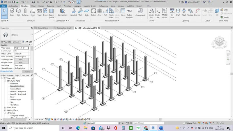
- Columns are placed in the model.
- Go to ground floor, For beams select beams command in structure select the required beam place it with pick lines command.
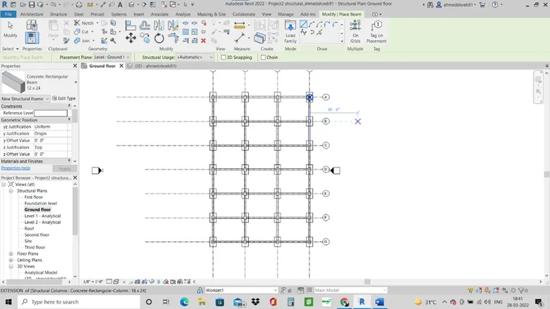
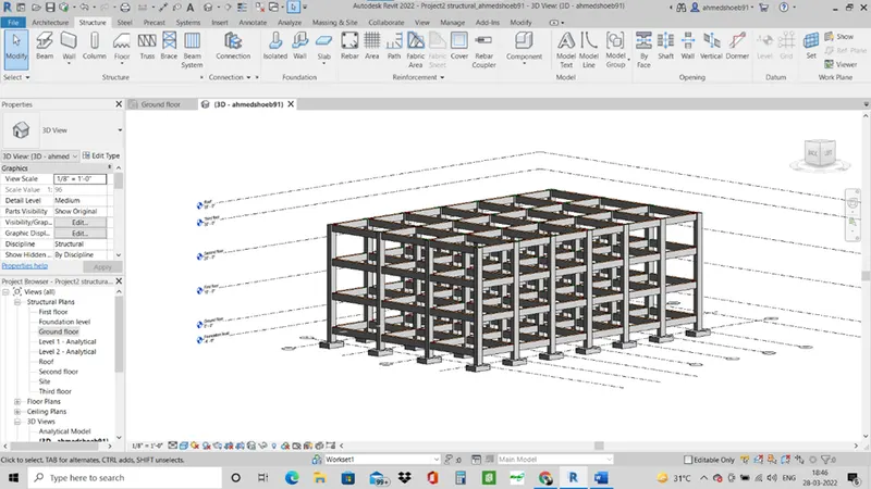
- Copy the beams and paste it accordingly in first floor, second floor, third floor of the building. Beams are placed in the model.
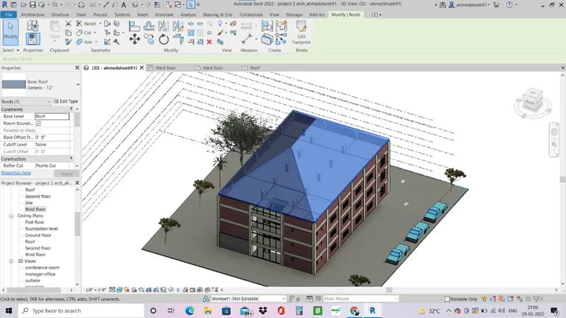
- For roofs, go to roof floor and select the roof command in structure and>roof by footprint. Place the roof border on the outside of the building and place the roof accordingly.
- Go to ground floor, select the floor command and select the line command and sketch the lines of the floor. Floor is created.
- Copy and paste the floor to the aligned selected levels of first floor, second floor, third floor.
- Go to Architecture and select the shaft command on the right.
- Draw the floor openings where you want to place the stairs, select the base constraints as ground floor and top constraint as roof and give an offset of 5’ on both side.
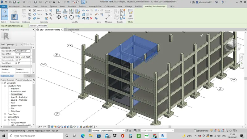
- Opening for stairs are created.
- Save the file as structural.
Result –
The structural frame of the project is created in the revit and saved.
4- AIM- Using the architectural model, include the following components based on the type of structure selected
Wall Layout with appropriate material and finishing
b. Exterior façade with fancy finish
c. Interior partition walls to size rooms
d. Components to add details to a room (Desk, Chair, Lighting, Plumbing fixtures)
e. Add components such as stairs Elevators
f. Have at-least one side of the building with curtain walls and glass panels
g. Include interior and exterior lighting fixtures
h. Place proper topographic components from outside (Trees, Parking, Plants) to add details to the model
Procedure –
- First open the Revit software.
- Select new project and architectural template.
- Make grids using grid command.
- Go to manage and specify the coordinates at 0,0
- Specify the base project point at 0,0,0. This will set the coordinates at a absolute value.
- Now go to manage and collaborate the project and save it as central model.
- Go to manage tab and manage links and insert the revit structural file in the through project base point to project base point.
- This will make the structural project and architectural grids aligned.
- Now you can add walls to the structure through wall command in architecture.
- Select the base constraint as ground floor and top constraint as roof.
- One side of the is store front for aesthetic purposes.
- Walls are added to the structure.
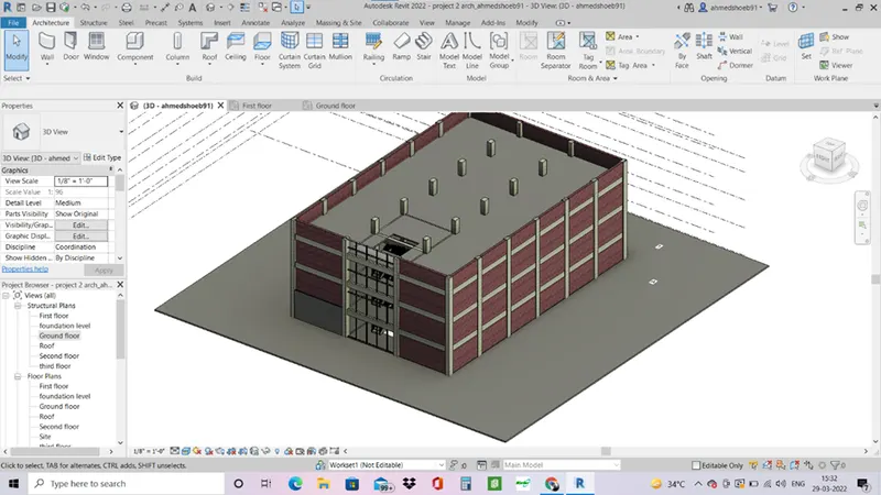
- Interior walls are added as partition walls.
- Go to stairs command and design the stairs as required.
- Railing component of the stairs can be edited.
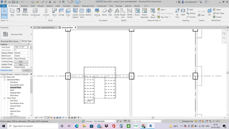
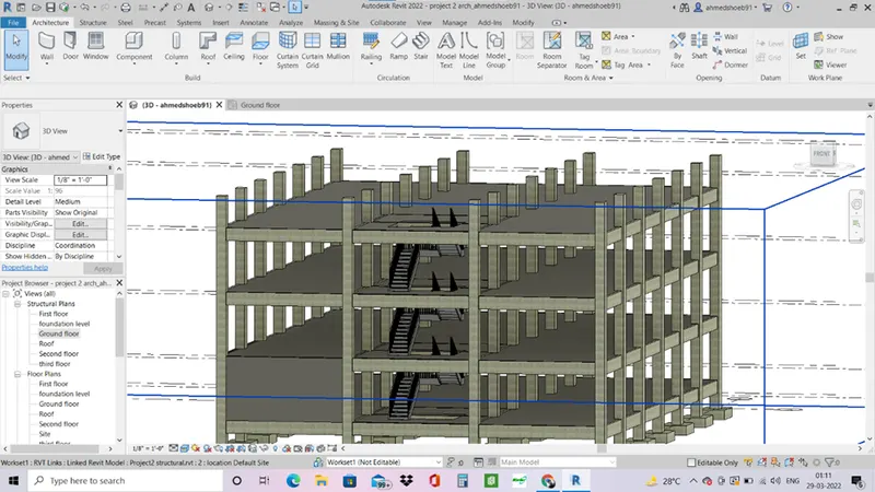
- Go to ground floor and add component to the building as required.
- If the required element is not present you can load it in revit trough load family and select the required component and placed it accordingly.
- Include the lighting fixtures in the model through load family.
- Plumbing components are also added.
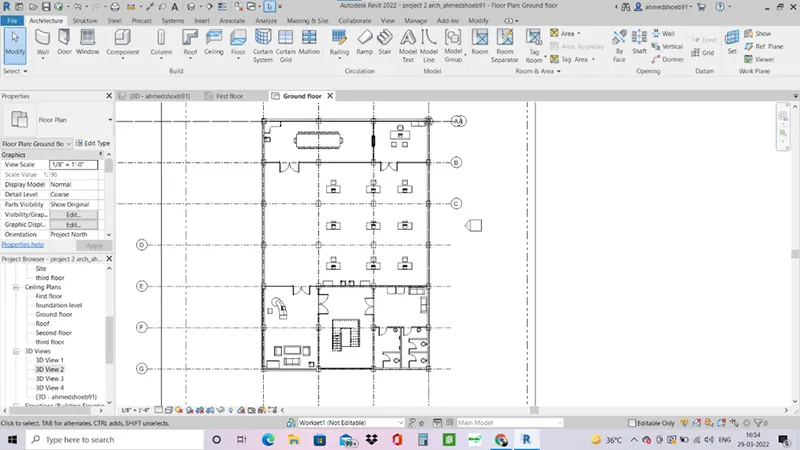
- Place the parking and topographic elements on the ground floor.
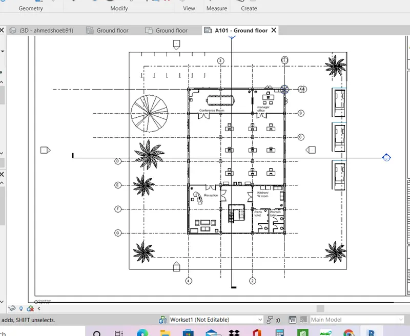
Result –
The Architectural elements of the building are added in the model.
5- AIM- Provide a set of drawings in an architectural and structural model to list the following details with categories and appropriate sheet templates included
Floor Plans with Annotations
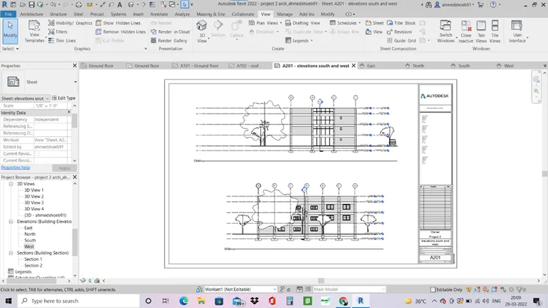
b. Elevations
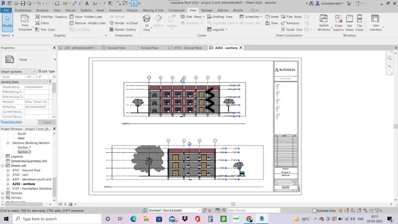
c. Sections
Procedure –
- Go to view and select sheet command.
- Load the required sheet such as A1 sheet size in revit.
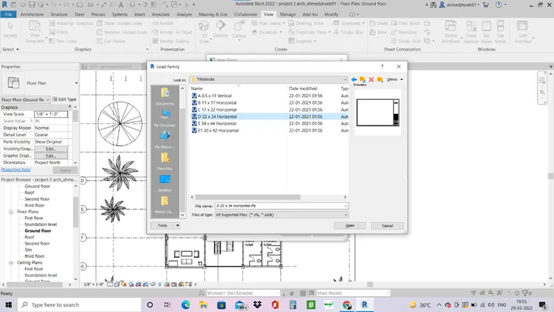
- Make the annotations changes such as floor plan name, number, date, issued by, check by etc.
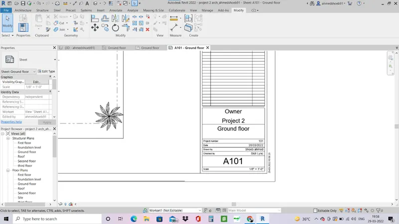
- Drag the view from the project browser on the sheet as set scale to fit the paper.
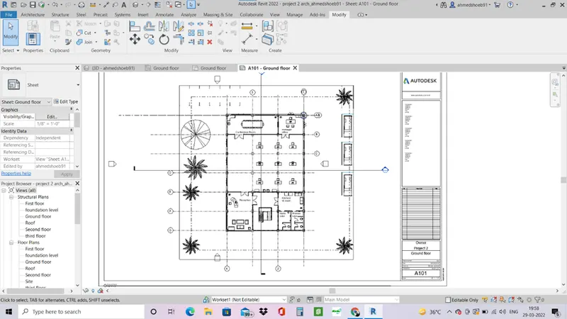
- Define different sheet name as sections then drag the section views, elevations for elevation views etc.
Result –
Sheets are created with appropriate name in the revit.
Floor plans-
Elevations
Sections
6- AIM- Using the Rendering settings, Render images of the 3D model produced and include the rendered images to the drawing sheets
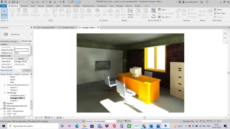
Rendering from interior rooms
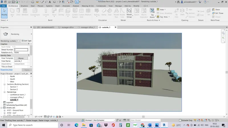
b. Rendering from out showing topographic features
c. Rendering through structural framing.
Procedure –
- Go to ground floor and view option in toolbar select the 3d view>camera.
- Now set the camera as the view is required.
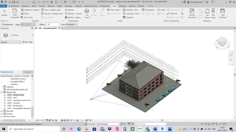
- Go in the camera view rename it as required and pan,orbit it as required.
- Set different cameras for the different views.
- Go in a specific view, press RR or render option for rendering.
- Adjust the requirements as required, and render the view.
- Save the rendering in the project.
- Open a new sheet and drag the rendered images on the sheet.
- Save the sheet as renderings.
Result-
Views in 3d are rendered , saved and sheet is formed for the rendered views.
- Rendering from interior rooms
-
- Rendering from out showing topographic features
-
- Rendered images on sheets
-
7- AIM- Print the set of drawing sheets created and submit the drawings from the architecture and structure model
Procedure-
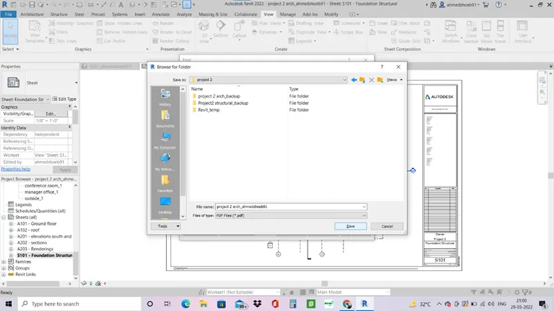
- Select the sheet from the project browser.
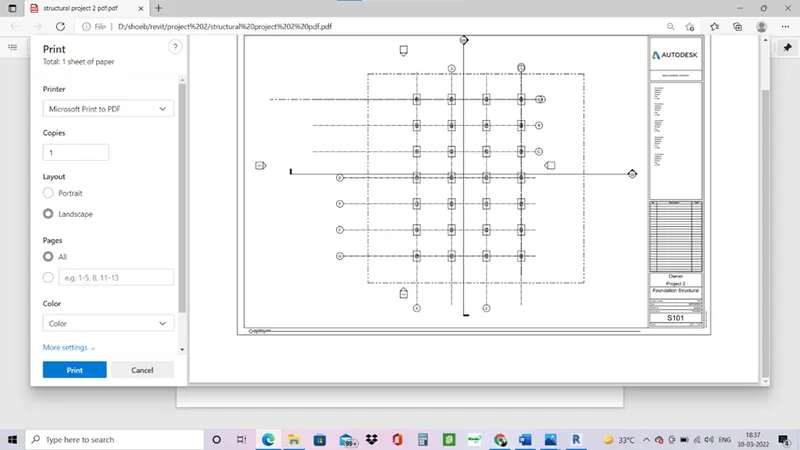
- Enter ctrl+p command for print.
- A dialogue box is opened then select Microsoft to printer option and sheet changes are made accordingly.
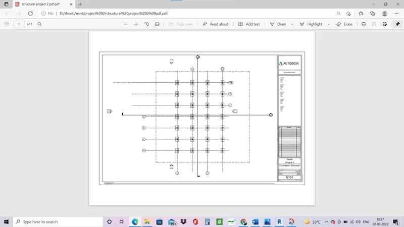
- Press enter and the file will be saved as pdf to print.
Result-
The drawing sheets are printed for architecture and structural sheets.