Creating Architectural and Structural model with 3D rendering using REVIT
1)
AIM: To Select the type of structure you want to build from one of the three Multi-Unit Residential Apartment or Office Buildings or School.
PROCEDURE: The type of structure i want to build from among the above three is Office Buildings.
RESULT: Office buildings
2)
AIM: To assume reasonable assumptions for geographic and location details for the project modeling. Based on assumptions and type of structure selected we need to identify the modeling requirements from NBC
PROCEDURE: For the 2nd type building or Office Buildings some criteria to be followed according to NBC are:
1. The open space around the building should not be less than 4.5m.
2.The FAR value for business building shall be taken as 2.9
3. The plot size is taken as 40*70 m that is 2800m2 and individual floor area is 2000m2. Hence FAR value obtained is 2.14 which is within the prescribed limit .
4.The width of road abutting the building is taken as 9m (30')
RESULT: Some NBC codes for office buidings in chennai.
3)
AIM:In the structural model, include the following components based on the type of structure selected
a. Foundation – Isolated / Wall/Matt Foundation
b. Columns
c. Beams Connected to Columns
d. Roof Framing/ Truss
e. Floor / Decks
f. Floor Openings for Elevators and Stairs
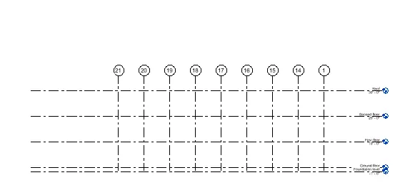
PROCEDURE: open the structural model Create level foundation level ground floor level, first floor level, second floor leveland roof level.
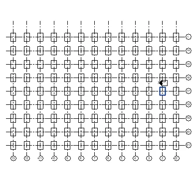
a. Open ground floor view and then go to structural tab and select isolated foundation option then select at grids and then select all the grids
 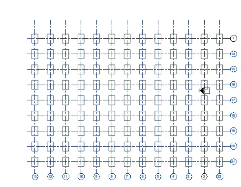 and then finsh
 .
.
b. Again go to structure tab and select column option  and then select vertical column option
 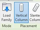 and then select at grids
 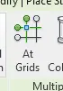 then select the type of column and size
 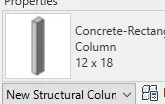 and select all the grids aand give the height of the column till second floor.
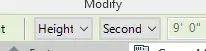 and then finish the columns are created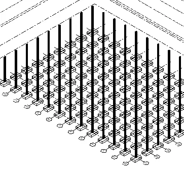
c. Again go to structure tab and select Beam option in the ground floor view slect the type of beam
 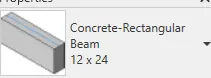 and the select on grids otion and then select all grids and then finish the beams are created similarly
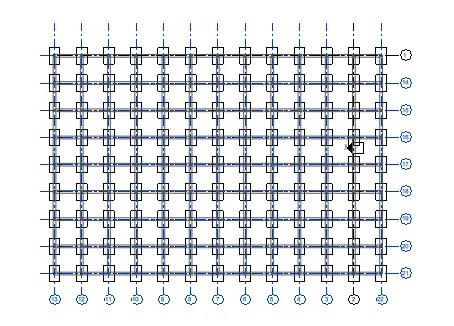 do it in the first floor plan view and second floor view.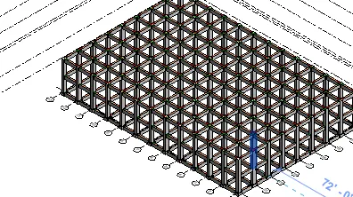
d. Go to the structure tab select truss option go to second floor view and select draw option
  and and draw line in the cornerws of the layout.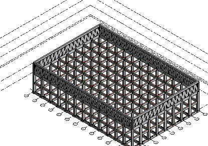
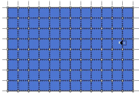
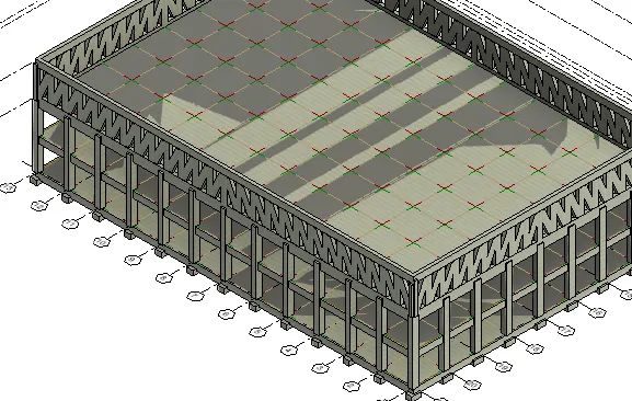
e. Go to the structure tab and select floor option in the ground floor level select the type of floor then 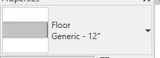 and then select the boundary plane using rectangular
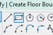 and draw the boundary
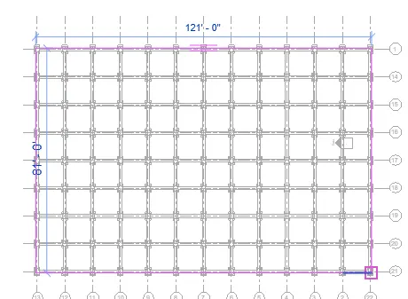 then finish simlarly select in first an dsecond floor from property browser.
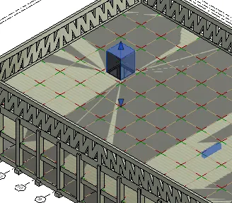
f. go to structural tab and select shaft option  then using rectangle draw the shaft opening
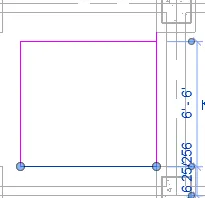 and then close
  .
.
RESULT:
a.
b.
c.
d.
e.
f.
4)
AIM:In the architectural model, include the following components based on the type of structure selected
a. Wall Layout with appropriate material and finishing
b. Exterior façade with fancy finish
c. Interior partition walls to size rooms
d. Components to add details to a room ( Desk, Chair, Lighting, Plumbing fixtures)
e. Add components such as stairs Elevators
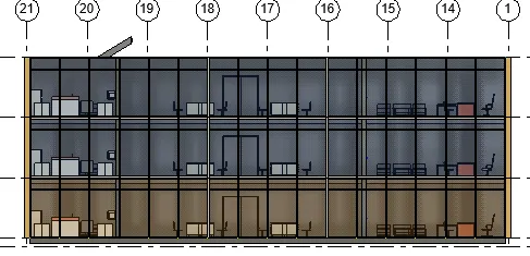
f. Have at-least one side of the building with curtain walls and glass panels
g. Include interior and exterior lighting fixtures
h. Place proper topographic components from outside ( Trees, Parking, Plants) to add details to the model
PROCEDURE:
Draw the levels same as the structural model and name them .
a. in the architectural model select wall option and from property select the type of wall 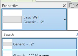 and then draw the wall in the grids
 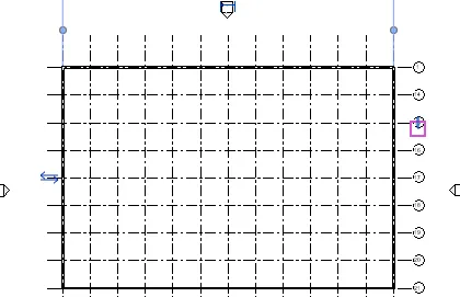 and give height till first floor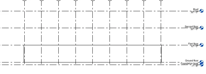
b. select the wall and go to edit properties and then duplicate and then go to category
  and select material in the material browser
 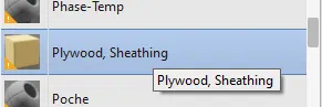 and then apply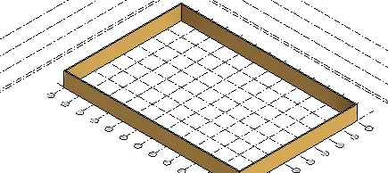
c. go to architecture tab and select wall option and select the wall type 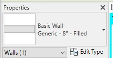 and the draw the inner walls according to rooms partition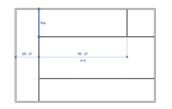
d. go to insert option and then load family and select equipments as per requirements such as table desk , chair , plumbing fixtures urinals basins bathrooms mirrors then kitchen equipments and seatings like microwave oven refrigerator gas stove and sinks then the reception desk and chair and then finally the managers room desk and chair.. then from architecture tab go to add component select the object and place in plan one by one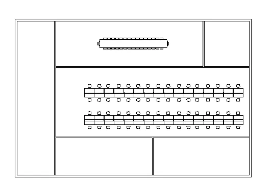
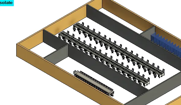
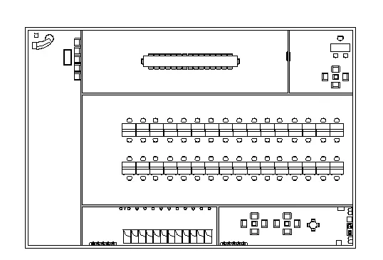
e. select the floor plan in the ground floor plan and then click copy option and then paste option from paste option select aligned to different levels
 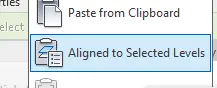 and select first floor and second floor.
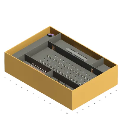
Then from the architectural tab select stairs option and draw stairs in beween levels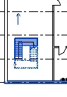 then go to shaft opening and select the area of stairs.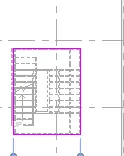
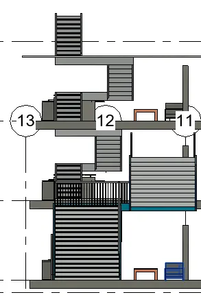
create a shaft opening and then in the opening from structural plan using insert family place the elevator.
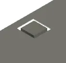
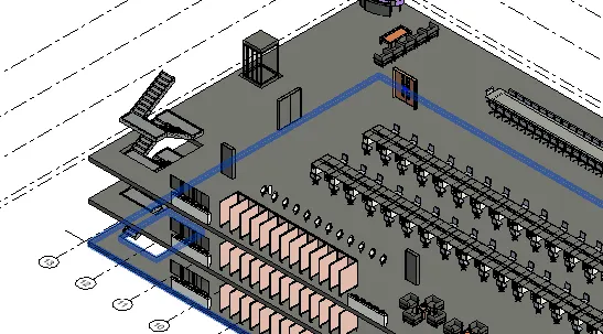
f. Select the wall of the front side of the building and from the properties change the wall type to curtainwall storefront.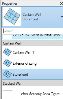
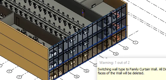
g. Go to insert tab and select load family and then go to lightings and lighting fixtures internals.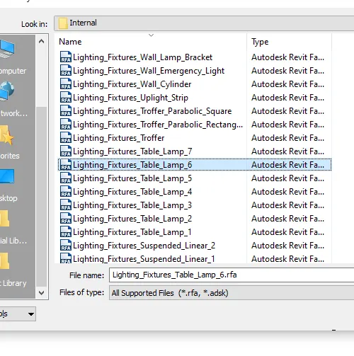 then select the type of lighting go to the required view and add it to the drawing.
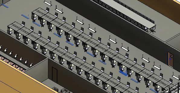 to draw this add ceiling and then in 3Dview add it.
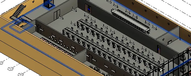 similarly add few other lighting fixures
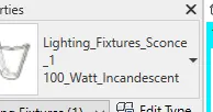 .Then from the load family go to external lighting fixtures and add street lamp in the surrounding by drawing the floor with offset -12" in the ground floor. and adding lamps over there.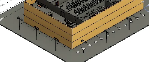
h. Then from the insert tab go to load family option then parking and select parking type 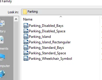 and add to the plan.
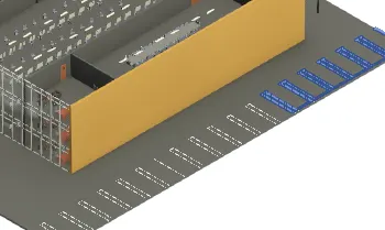 then similarly from planting in the load family
 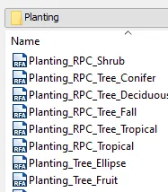 add plants to the drawing.

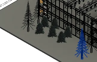
RESULT:
a.
b.
c.
d.
e.
f.
g.
h.
5)
AIM:To Provide a set of drawings in an architectural and structural model to list the following details with categories and appropriate sheet templates included
a. Floor Plans with Annotations
b. Elevations
c. Sections
PROCEDURE:
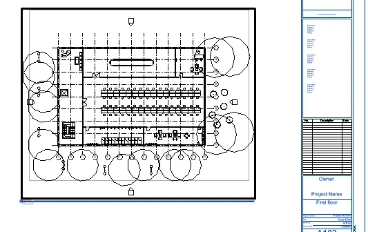
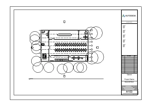
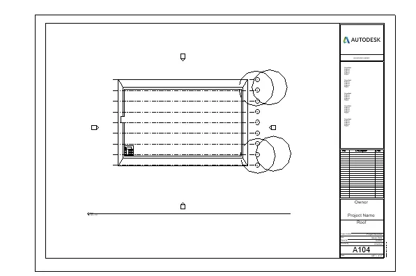
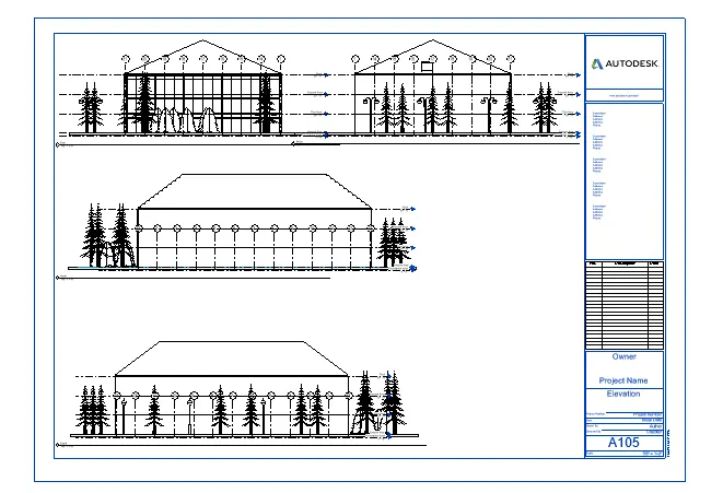
Go to view tab and select sheet otion select the size of sheet 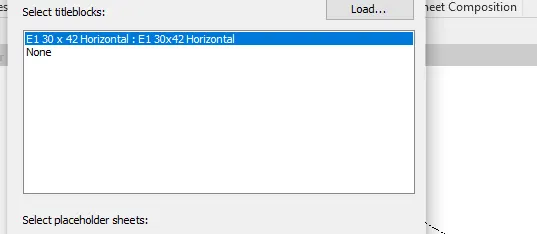 and click ok.
a. from the project browserr tab select the floor plan view  one byone and drag them to the sheet.and rename them.
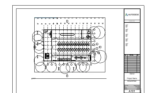
b. from the project browserr tab select the Elevation view one byone and drag them to the sheet.and rename them.
c. Then go to ground floor plan view and from the view tab draw sections in the plan .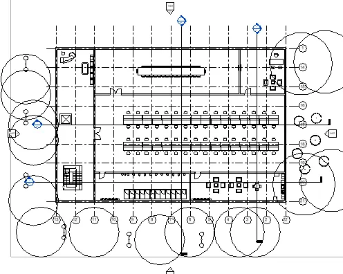
then from property browser go to the section view and similarly drag all the views to the sheets.
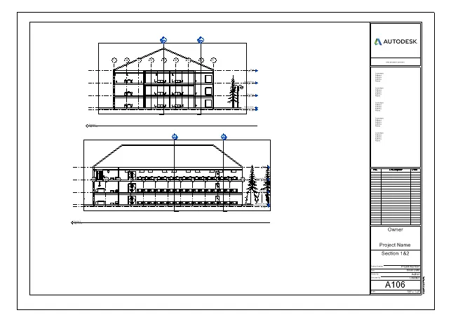
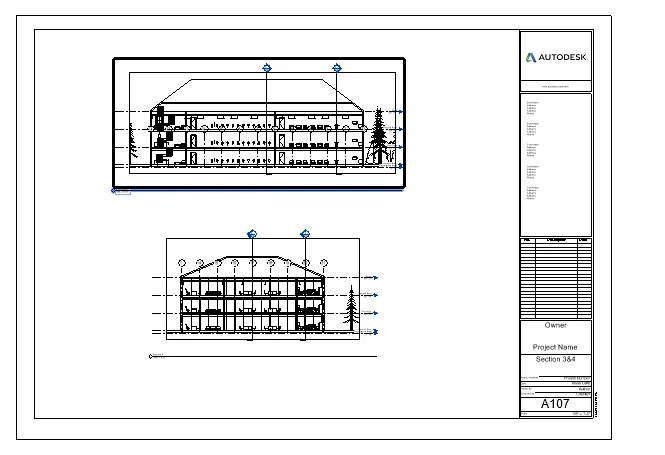
RESULT:
a.
b.
c.
6)
AIM:To Render images of the 3D model produced and include the rendered images to the drawing sheets
a. Rendering from interior rooms
b. Rendering from out showing topographic features
c. Rendering through structural framing
PROCEDURE:
a.Go to view tab and then second floor view and add camera to all the rooms and rename it according to room. Go to the 3d view from project browser and select the 3dviews .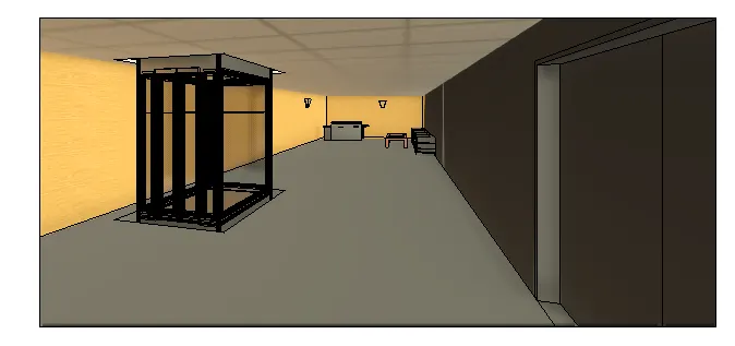 reception
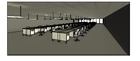 working area
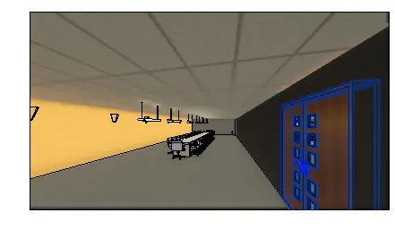 meeting areaetc.
now go to the render comand from view tab. and select medium and render all the views one by one .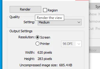 select lighting sun and artificial lighting.
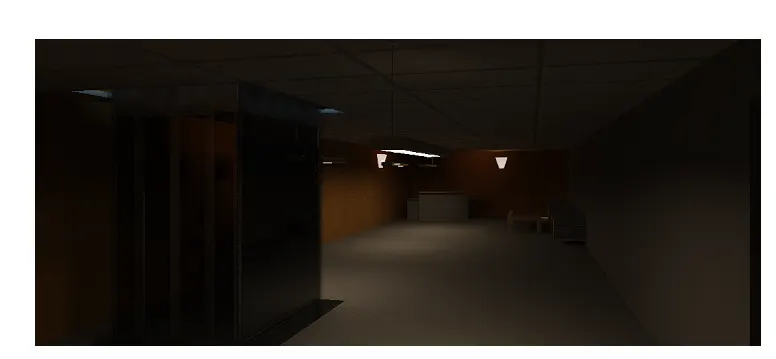 reception.
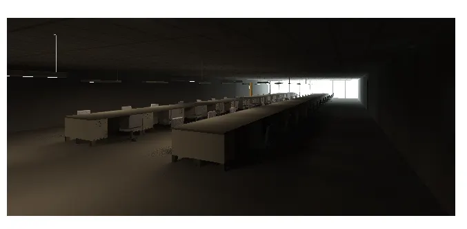 working area.
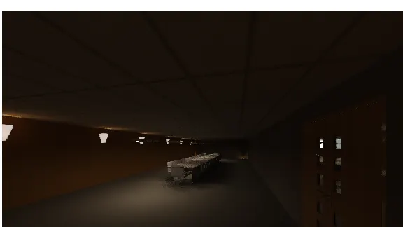 meeting area.
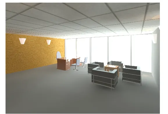 Manager room.
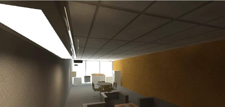 cafeteria.
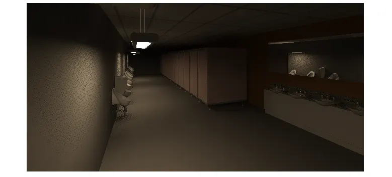 washroom. Add the views to the sheets.
b. go to 3d view add a camera and name the view as exterior. now go to render and render the view .
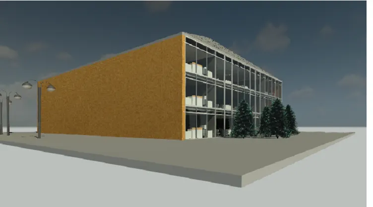 add the view to the sheets.
c. open structural view and add a camera and save the view as structural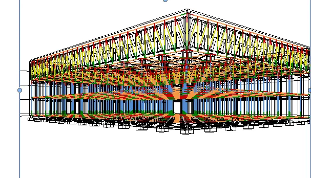 and then render the view.
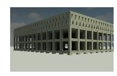 add the view to the sheet.
RESULT:
a.
reception.working area.meeting area. Manager room.
cafeteria.washroom.
b.
c.
7)
AIM:To Print the set of drawing sheets created and submit the drawings from the architecture and structure model
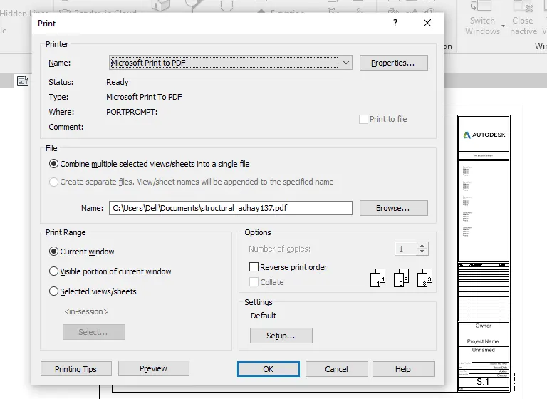
PROCEDURE: open the sheets and press ctrl+p a dialog box appears select the page setup and the printer and press okay for all the sheets.
RESULT: