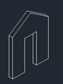
Creating a Floor plan, Footing detail and Isometric view using AutoCad
Aim: to create given drawings using autocad applications and mention the steps used .
procedure:
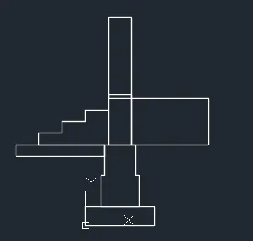
for c1:
give command rectangle
specify first corner point (0,0) then other corner point @(0.9,0.25)
give command pline
first point (0.2,0.25)then next point@(0,0.4)then next point@(0.05,0)then next point@(0,0.4)then next point@(0.4,0)then next point@(0,-0.4)then next point@(0.05,0)then next point @ (0,-0.04) close or esc.
give command rectangle
specify first corner point (0.3,1.05) then other corner point @(0.3,0.65)
give command rectangle
specify first corner point (0.3,1.65) then other corner point @(0.3,1.05)
give command line
specify first point(0.3,1.5)then next point @(-0.3,0)then next point @(0,-0.15)then next point @(-0.3,0)then next point @(0,-0.15)then next point @(-0.3,0)then next point @(0,-0.15)then close.
give command rectangle
specify first corner point (0.25,1.05) then other corner point @(-1.15,-0.15).
give command rectangle
specify first corner point (0.6,1.05) then other corner point @(1,0.6).
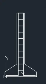
for c2:
give command pline
specify first point(0,0)then next point @(0,0.15)then next point @(0.38,0.25)then next point @(0,1.6)then next point @(0.24,0)then next point @(0,-1.6)then next point @(0.38,,-0.25)then next point@(0,-0.15) then close.
give command pline
specify first point(0.04,0.04)then next point @(0.38,0)then next point @(0,1.96)then next point @(0,0.16)then next point @(0,-1.96)then next point @(0.38,0)then close.
give command line
specify first point (0.42,1.8) then next point @(0.16,0) then copy command dispacement put base point( 0.42,1.8) then select array number of times to array 9 then displacement @(0,-0.2).
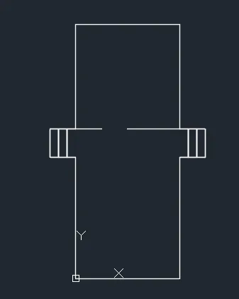
for c3:
give command rectangle first corner point (0,0)next corner point@(3.6,4.2)
give command rectangle first corner point (0,4.2)next corner point@(-0.3,1)then copy select base point(0,4.2)then select array no. of arrays put 3 second point @(-3,0) then again copy the whole array select first base point (0,4.2)and other base point (4.5,4.2).
give command pline
first point(0.9,5.2)then next point@ (-0.9,0)then next point@ (0,3.6)then next point@ (3.6,0)then next point@ (0,-3.6)then next point@ (-1.8,0)
then use the trim tool to remove the unwanted lines that is the line from point (0,4.2)to (3.6,4.2)and the line from point (0,4.2)to(0,5.2) and the line from point (3.6,4.2)to(3.6,5.2).
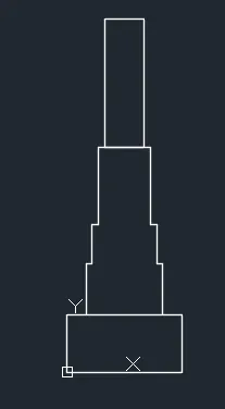
for c4:
give command rectangle
first corner point (0,0)next corner point@(0.9,0.45)
give command line
first point(0.15,0.45)then next point @(0,0.4)then next point @(0.05,0)then next point @(0,0.3)then next point @(0.05,0)then next point @(0,0.6)then next point @(0.4,0)then next point @(0,-0.6)then next point @(0.05,0)then next point @(0,-0.3)then next point @(0.05,0)then next point @(0,-0.4)then exit command.
give command rectangle
first corner point (0.3,1.75)next corner point@(0.3,1)
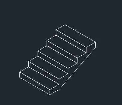
for c5:
select isometric drafting.
selct orthomode.
give line command .
select left plane in isometric drafting.
select a base point.
move the cursor in left plane and give the distance 1.
move the cursor in up direction give the distance 0.15.
move the cursor in the down direction and give the distance1.
then close.
then select right plane in isometric drafting give line command and give the base point on top left corner of the plane then move cursor in right plane and give distance 0.3 and then move cursor in right and give distance 1 and close.
copy the above plane
select the base point bottom left point and select the array put number of array 5 then put next point where to be placed in the top left corner of the drawing.
give line command
then select the first point or the base point of the drawing and give distance 0.3and then close.
for c6:
select isometric drafting.
give line command .
select left plane in isometric drafting.
select a base point.
move the cursor in left direction and give the distance 0.3
move the cursor in up direction give the distance 3.
movw the cursor in right direction give the distance 0.3.
move the cursor in the down direction and give the distance3.
then close.
select right plane .
give line command
select the endpoint in top right of the previous drawing as the first point of the line and give distance3.
select left plane in isometric drafting.
give line command
select base point as the end of the previous line
move the cursor in the down direction and give the distance3.
move the cursor in left direction and give the distance 0.3
move the cursor in up direction give the distance 3.
movw the cursor in right direction give the distance 0.3.
now select the right plane in isometric drawing and from the midpoint that is 1.5 distance draw a line of distance 1in up direction and close the end point of the line to the end points of the first drawing.
then copy the tuss and place it on 0.3 distance to the top.
select right plane in isometric drawing
now from the bottom point move the cursor to right to distance 1.then to the top to distance 2.42.then move the cursor to right to distance 1,then move the cursor to down to distance 2.42 and then move the cursor to right to distance 1.
Result:
c1:
c2:
c3:
c4
c5:
c6: