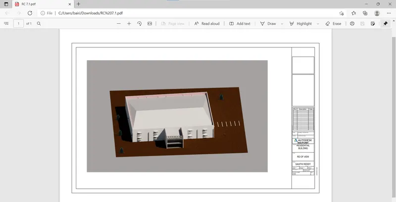
Creating Architectural and Structural model with 3D rendering using REVIT
1)
AIM:
To choose any one of the structure for designing and modelling out of the following:
a. Multi-Unit Residential Apartment
b. Office Buildings
c. School
RESULT:
I've chosen MULTI- UNIT RESIDENTIAL APARTMENT
2)
AIM:
To assume reasonable assumptions for geographic and location details for your project modeling. Based on assumptions and type of structure selected identify the modeling requirements from NBC
PROCEDURE:
- Open a new architectural template in Revit
- Go to manage tab and select location option from project location option
- Select the desired location
- Click ok
These are the major modelling requirements and assumptions made as per the NATIONAL BUILDING CODE:
- This falls under GROUP A- RESIDENTIAL BUILDINGS and under the sub section A5
- Height of the building has to be 40'
- Height of rooms should be 10'
- Thickmess of the walls should be 8"
- Main stair case and fire escape has to be continuous and from the ground floor to roof level
3)
AIM:
Using the structural model, include the following structural components based on the type of structure selected to design
a. Foundation – Isolated / Wall/Matt Foundation
b. Columns
c. Beams Connected to Columns
d. Roof Framing/ Truss
e. Floor / Decks
f. Floor Openings for Elevators and Stairs
PROCEDURE:
- Open a new structural file that has been created
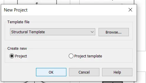
- Link structural file and architectural files that are created
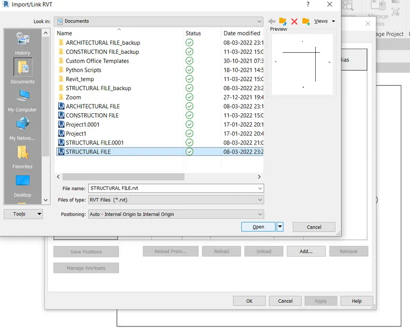
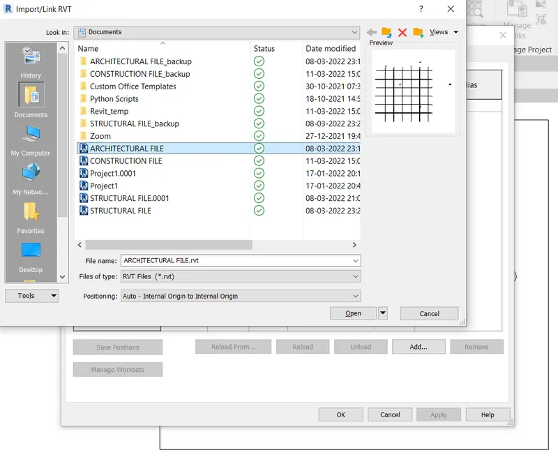
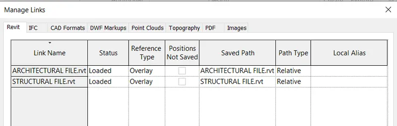
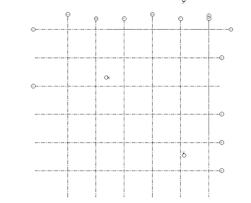
- Make sure the grids are located properly
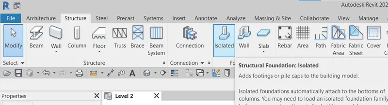
- Go to structure tab and select isolated footing
- Now select the at grids option to place the footing at the foundation level
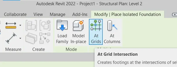
- Select thhe grids and click on finish option
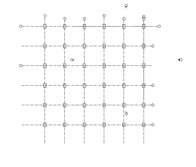
- Repeat the similar process to place columns at the grids intersection as well
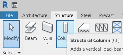
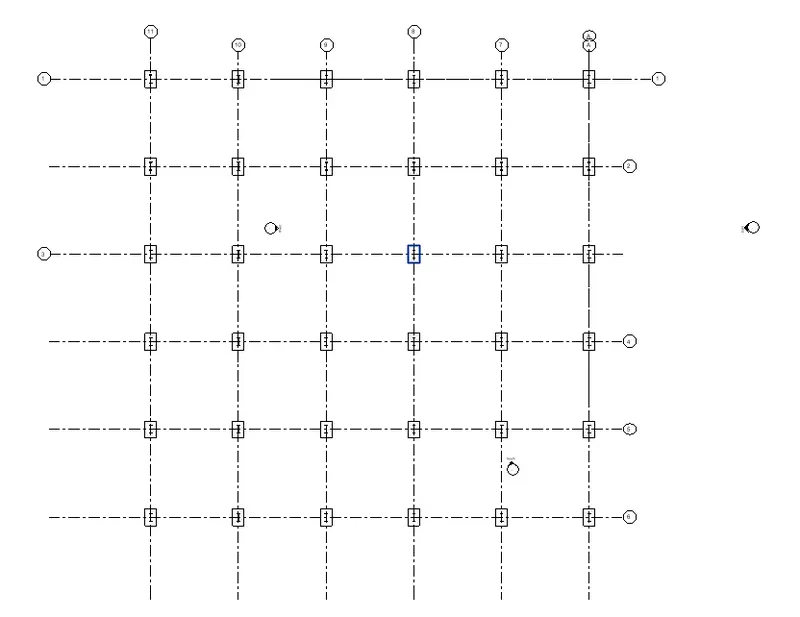
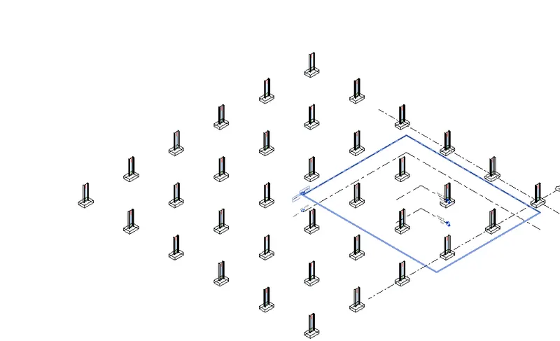
- Now go to structure tab and go to beam option
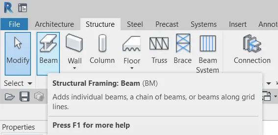
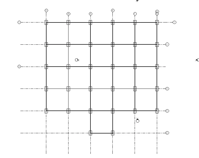
- Place the beams to make a girder system across the columns in every level
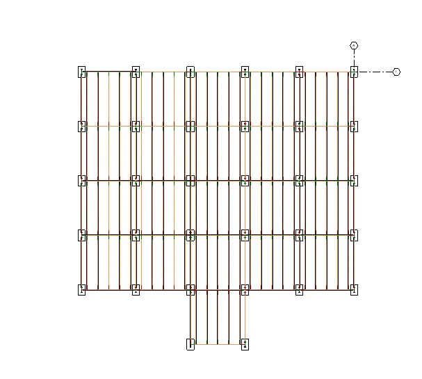
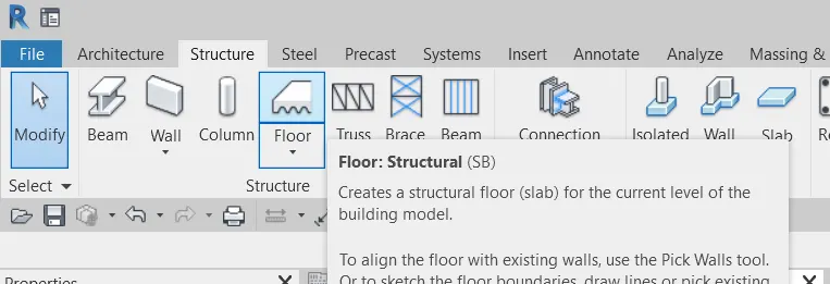
- Now go to floor option from structure tab and draw the floor outline on all levels
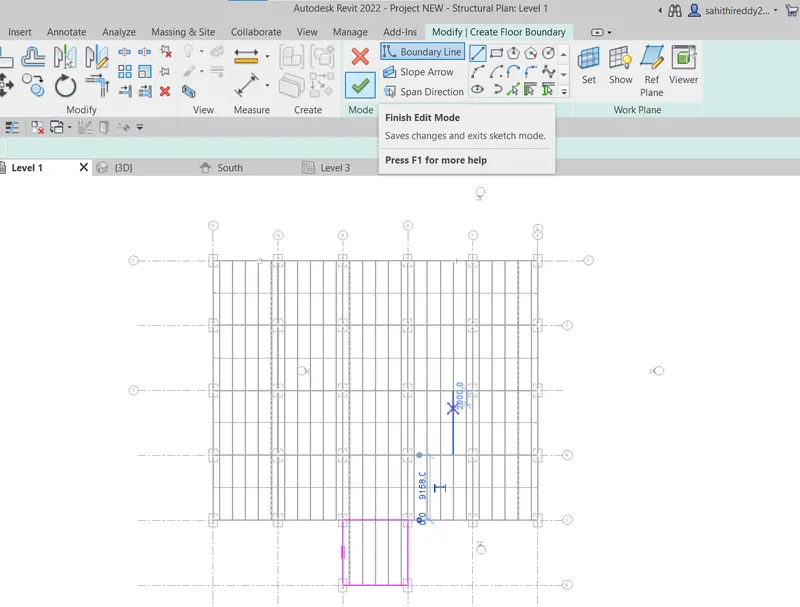
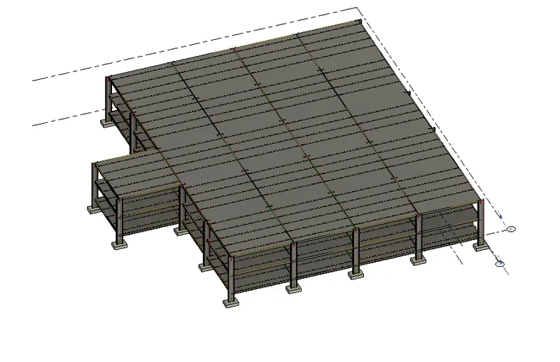
- Now to add shaft for stairs opening,select shaft option from the structure tab
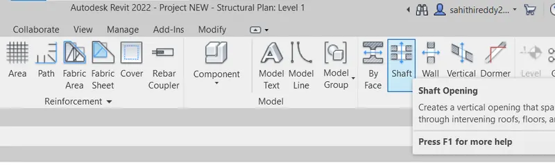
- Draw the area where we would like our stairs as a shaft opening
- Click on finish and our shaft opening for stairs has been created
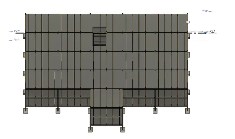
- Go to architecture tab and click on stairs to place them in the position

- Click on run and set the base constraint to ground level and selct the top constraint to the top most level
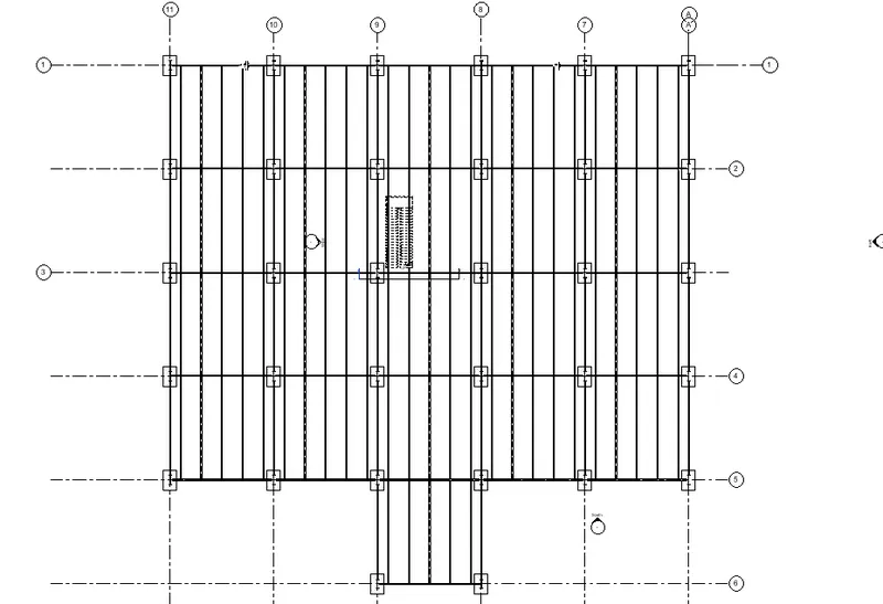
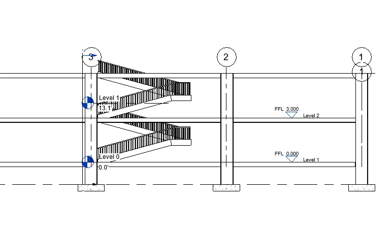
- Now to model truss select structure tab and then click on truss then select pick lines option
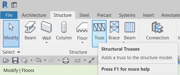
- Select the place truss is to be placed
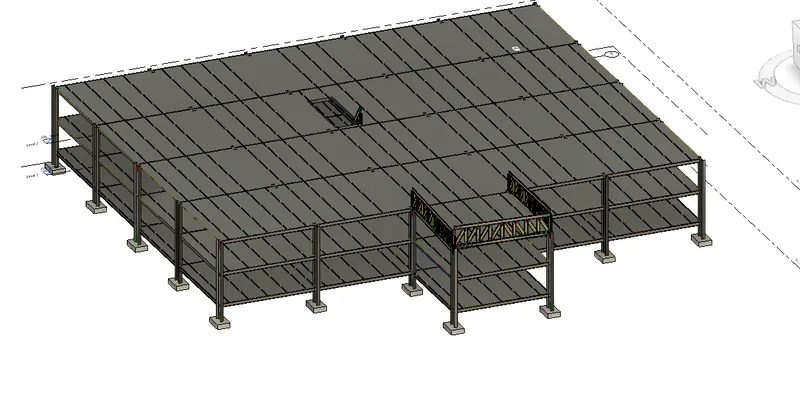
RESULT:
We have finished modelling for isolated footings, columns, beams, floor, stair openings and also truss
4)
AIM:
Using the architectural model include the following components based on the type of structure selected
a. Wall Layout with appropriate material and finishing
b. Exterior façade with fancy finish
c. Interior partition walls to size rooms
d. Components to add details to a room ( Desk, Chair, Lighting, Plumbing fixtures)
e. Add components such as stairs Elevators
f. Have at-least one side of the building with curtain walls and glass panels
g. Include interior and exterior lighting fixtures
h. Place proper topographic components from outside ( Trees, Parking, Plants) to add details to the model
PROCEDURE:
- Open the architecture file and as it is linked to the central model all the changes done in the structure tab also gets reflected in architecture file
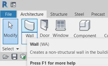
- To add walls got to architecture tab and walls , now select the exterior walls option and edit it as per requirements
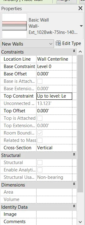
- Now select the desired wall type and place it accordingly
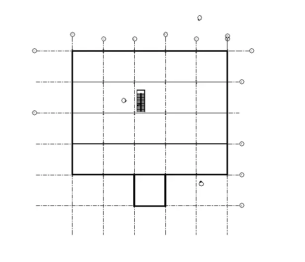
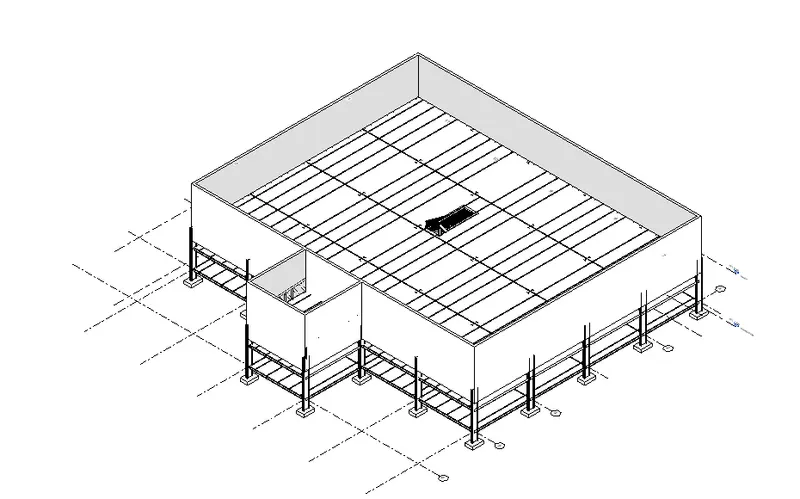
- Now start placing all the interior walls according to the partitions required
- So go to architecture tab and then walls and then select the desired wall type and place it
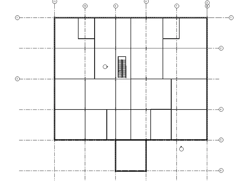
- Now start placing windows and doors in the required places
- Go to architecture tab and then to windows and doors and then place them
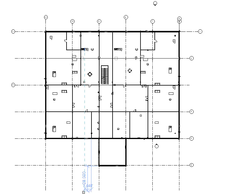
- According to requirements add different components in various rooms
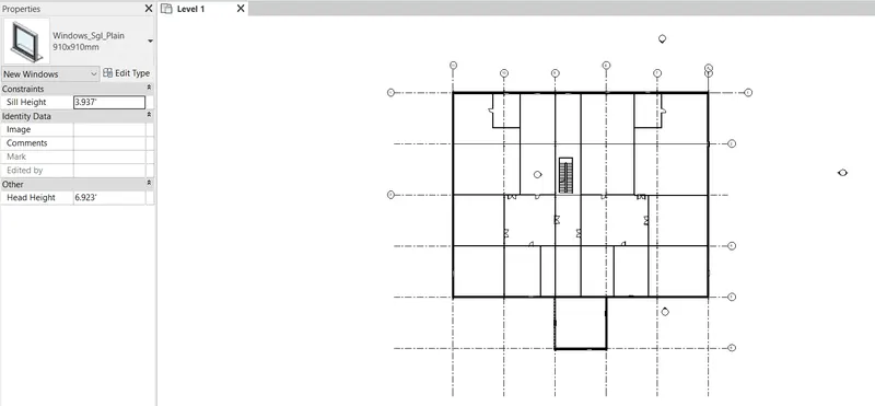
- To place those components first load those families and then insert them in the positions
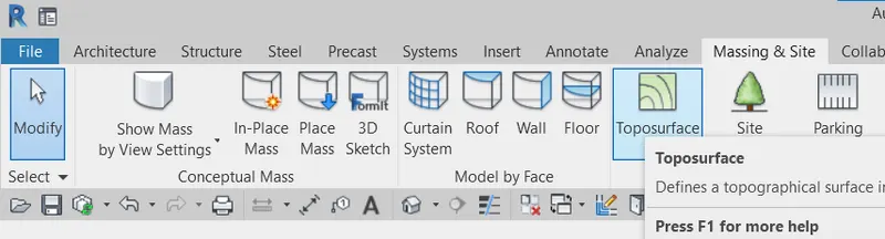
- Now to add topography go to the massing and site tab and then select toposurface option
- Plants and trees and other components can be added to topography using the site component option
RESULTS:
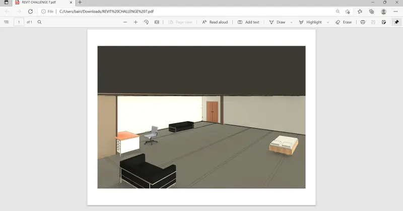
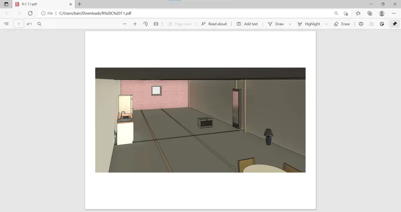
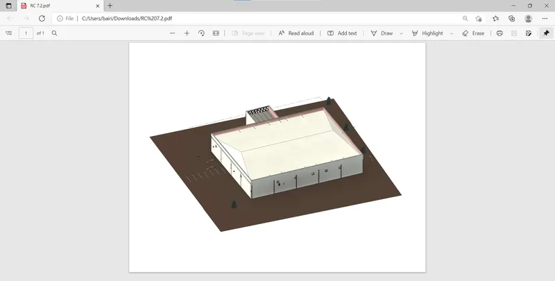
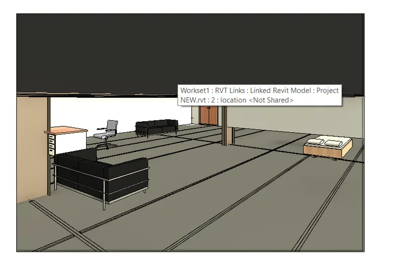
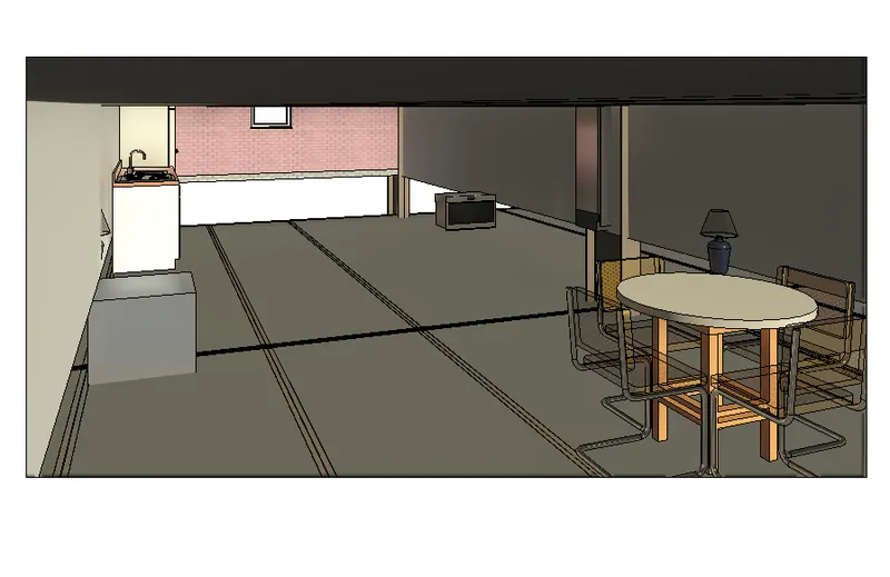
Below are the images of final results after modelling the rooms and topography components
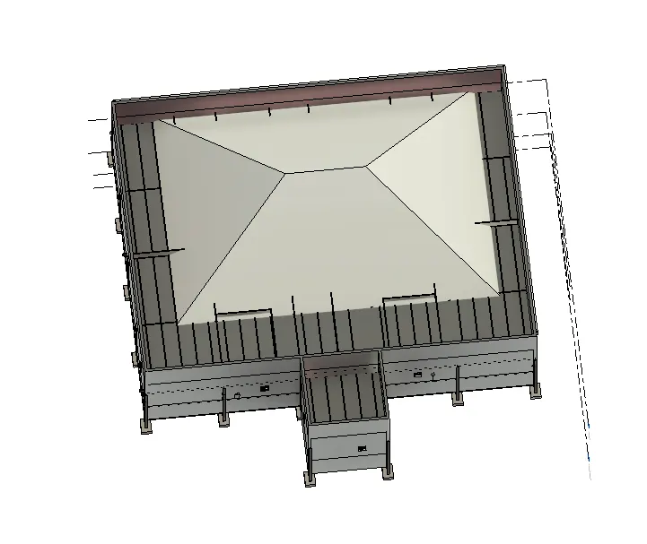
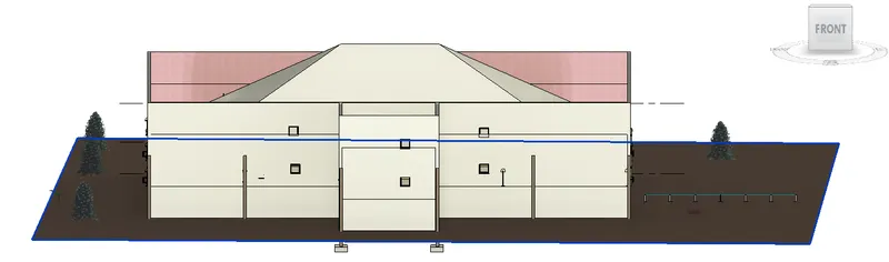
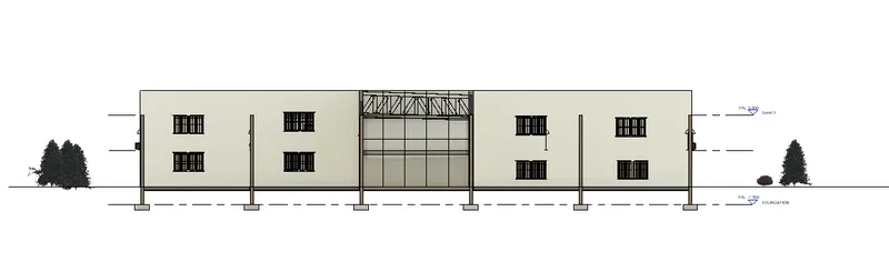
5)
AIM:
To provide a set of drawings in an architectural and structural model to list the following details with categories and appropriate sheet templates included
a. Floor Plans with Annotations
b. Elevations
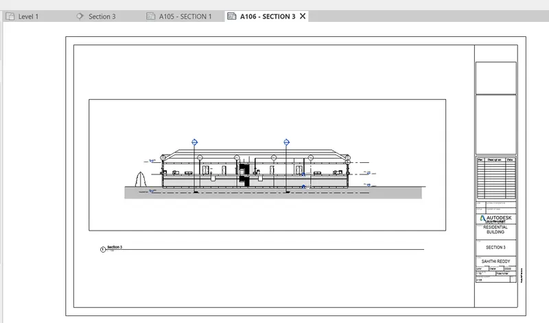
c. Sections
PROCEDURE:
- Open architecture file and go to annotate tab and then select aligned to give the dimensions to the project
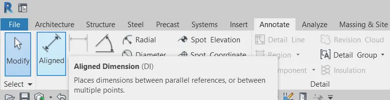
- Go to view tab and select sheet option to add sheets and then place the views on the sheet
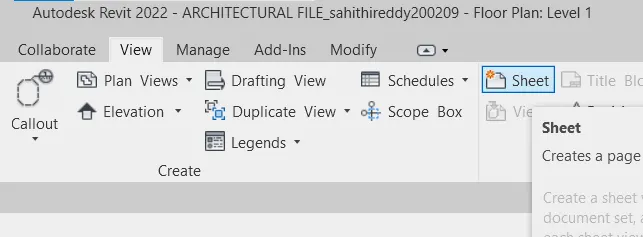
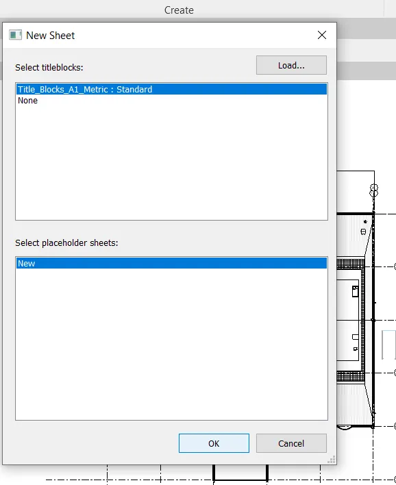
- Repeat the same procedure for elevation views and section views
RESULT:
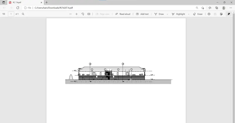
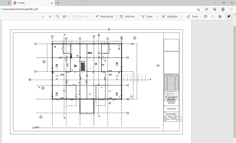
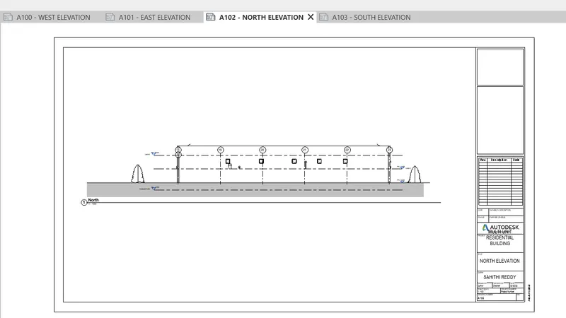
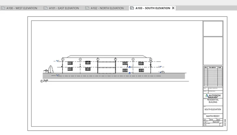
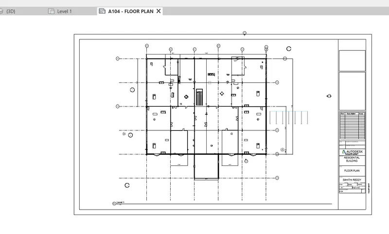
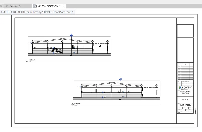
All the required sheets with the respective views and elevations and sections are modeled
ELEVATION VIEWS:
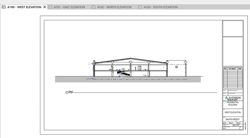
- WEST ELEVATION :-
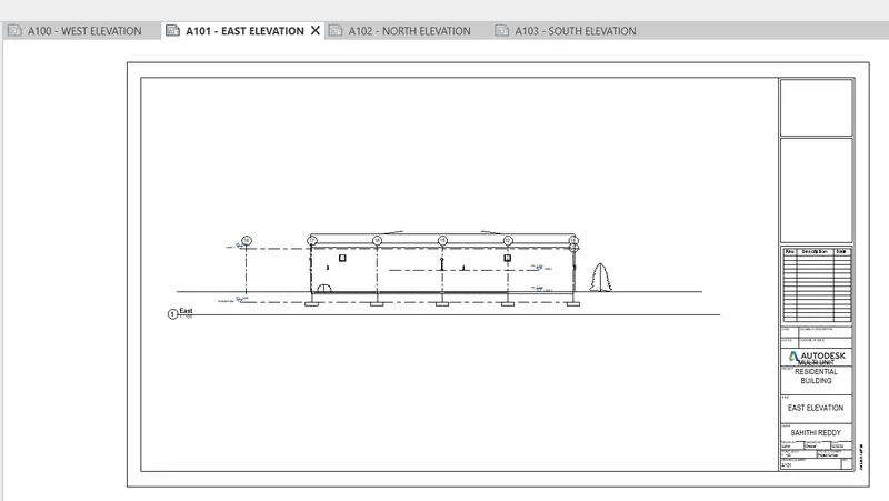
- EAST ELEVATION:-
- NORTH ELEVATION:-
- SOUTH ELEVATION:-
FLOOR PLAN:
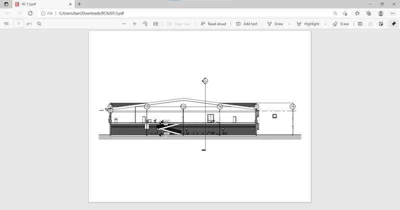
- SECTION VIEWS:
6)
AIM:
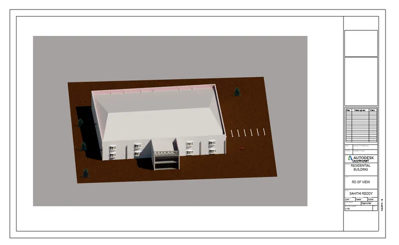
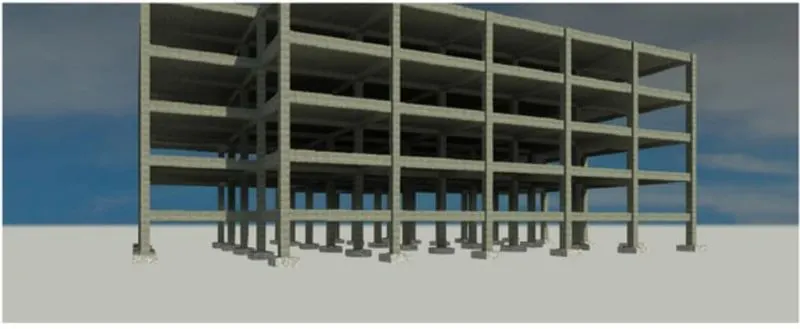
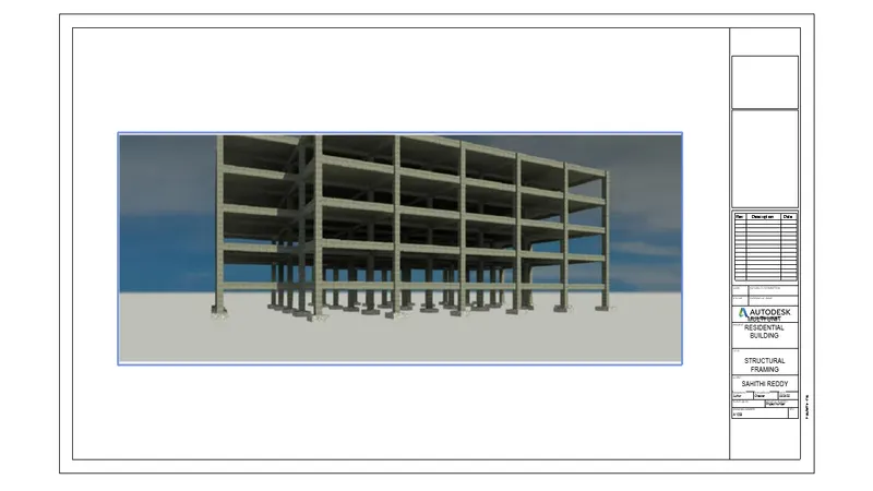
Using the Rendering settings to render images of the 3D model produced and include the rendered images to the drawing sheets
a. Rendering from interior rooms
b. Rendering from out showing topographic features
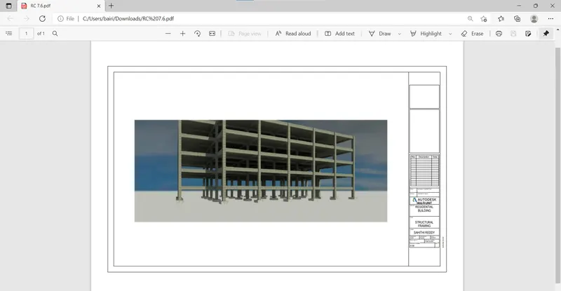
c. Rendering through structural framing
PROCEDURE:
- Open architecture file and go to view and create a camera specific view
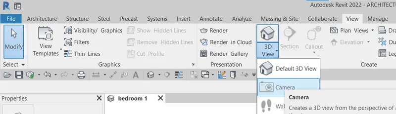
- Select show rendering option from vieew tab

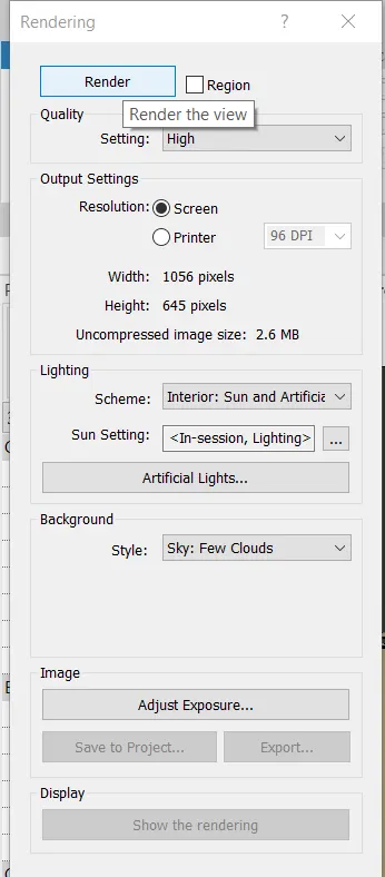
- Select the desired features and click on render
- Then save the rendered image to the project
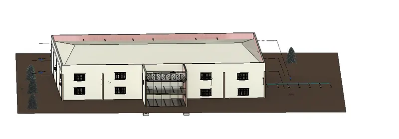
MODEL:
AFTER RENDERING:
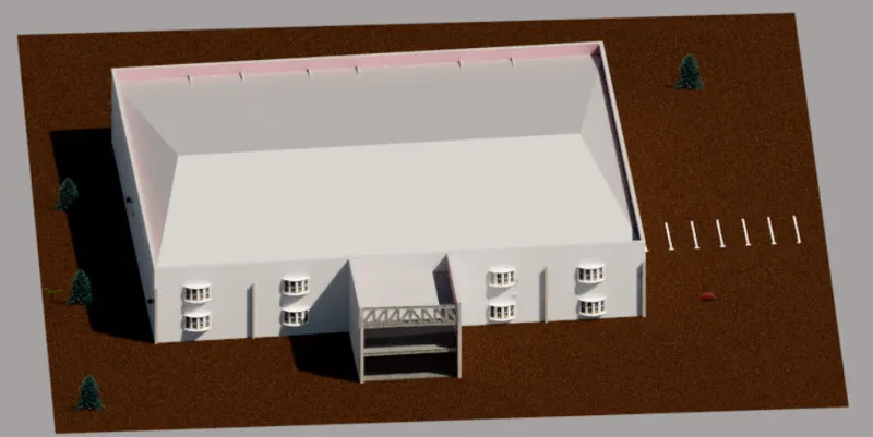
- Render all the views in the same way
BEDROOM:
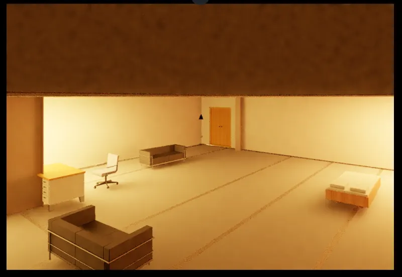
KITCHEN:
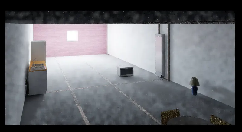
- Now similar to the previous project create the sheets with the rendered images in it
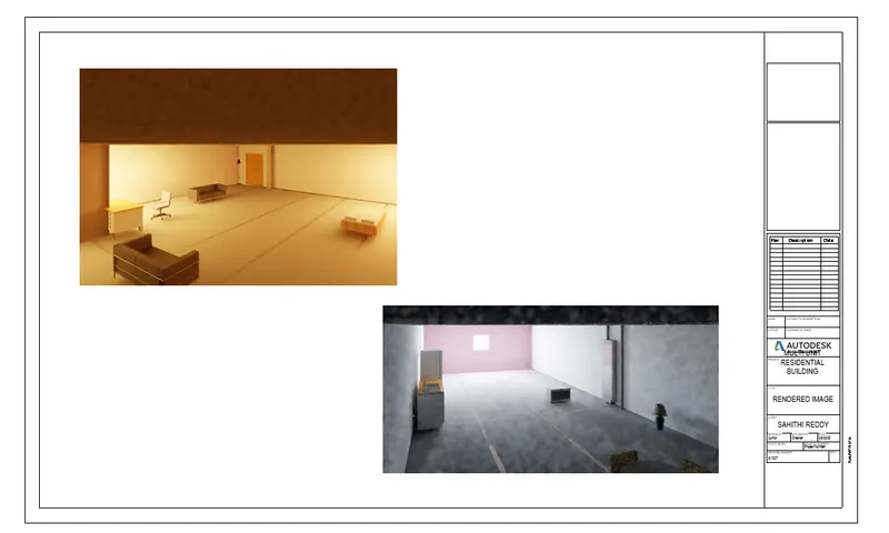
- Also render for structural framings in the structural model and place them in the sheets
RESULT:
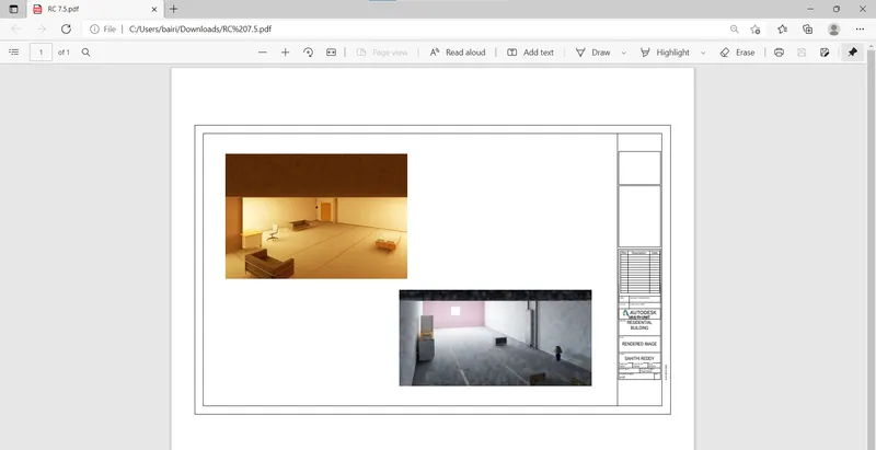
All the rendered views are added to the sheets
RENDERED IMAGE:
7)
AIM:
To print the set of drawing sheets created and submit the drawings from the architecture and structure model
PROCEDURE:
- Go to the above created sheets and press ctrl + p
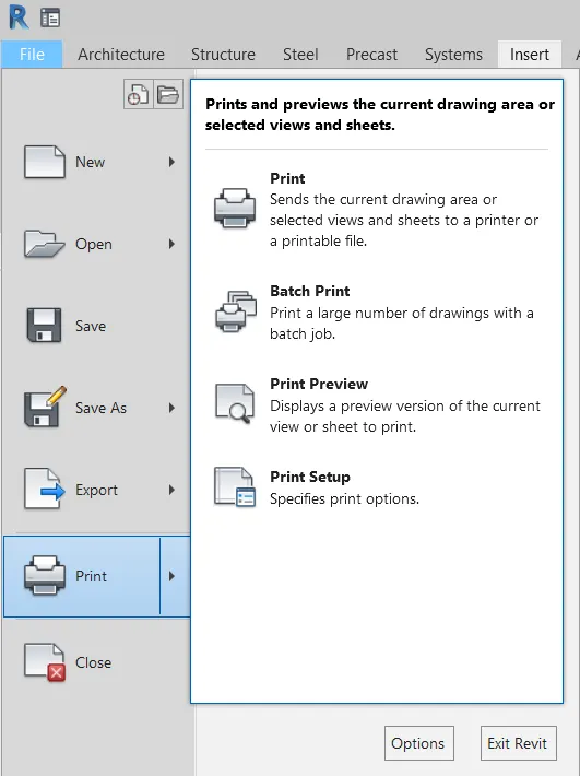
- A print dialog box will appear
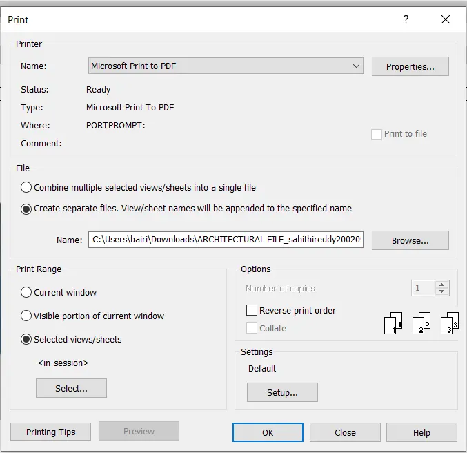
- Select the selected views option and click on select sheets
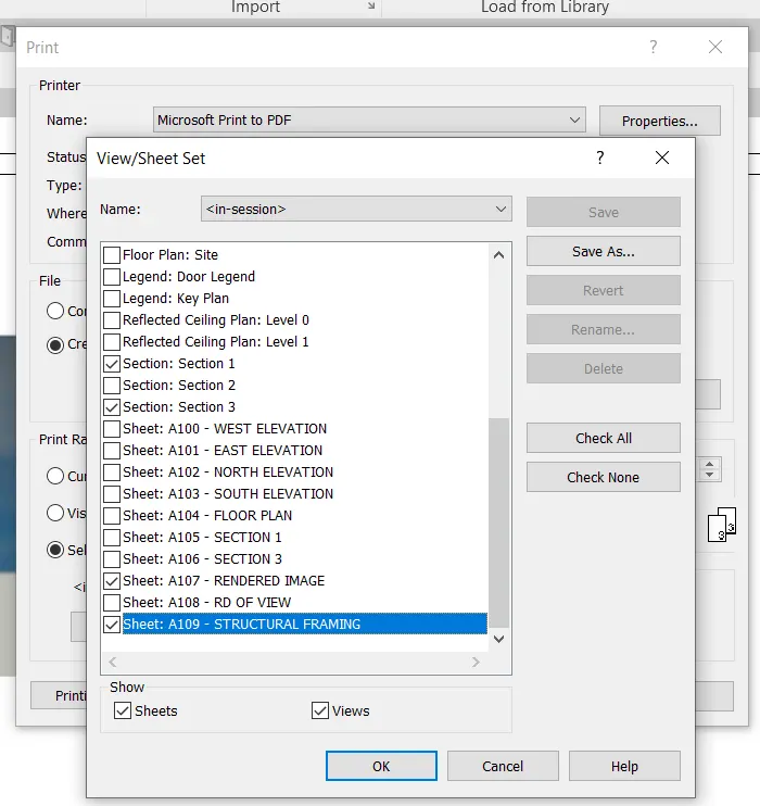
- Select all the sheets we want to print
- Then press ok
- Repeat the same with architecture files
RESULT:
All the architectural and structural sheets are printed