Creating Architectural and Structural model with 3D rendering using REVIT
1) Aim of this project is the select the type of structures that I will be creating here.
I would like to go for the office building.
2) Aim of this to make reasonable assumption based on the geographic and location details of the project.
Ans. As I have selected the office building following assumptions need to be considered.
a) The type of construction for the project is type 2. FAR value to be achieved is 2.9
b) Plot size is taken as 3600 sqmtr. Individual floor area is taken as 1800 sqmtr. G+2 Hence FAR is 1.5 with permissible limit as per NBC.
c) The width of the road is taken as 10mtr.
d) Open space around the building shall not be less than 4.5 mtr. It has also been considered.
3) Aim of this project is to include the components like foundation, column, beams connected to column, roofs, truss, floor openings for elevators and stairs.
Procedure:
a) First create the grid as per office plan/ structure frame plan after opening the structural template . At level 1 as ground floor I have created the grids in under structural tab by selecting the grid option.
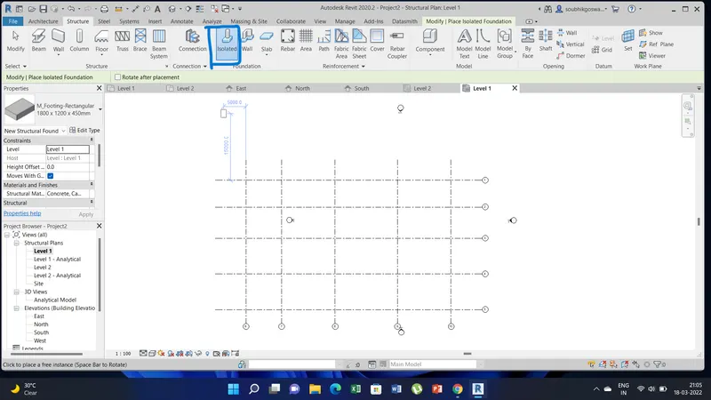
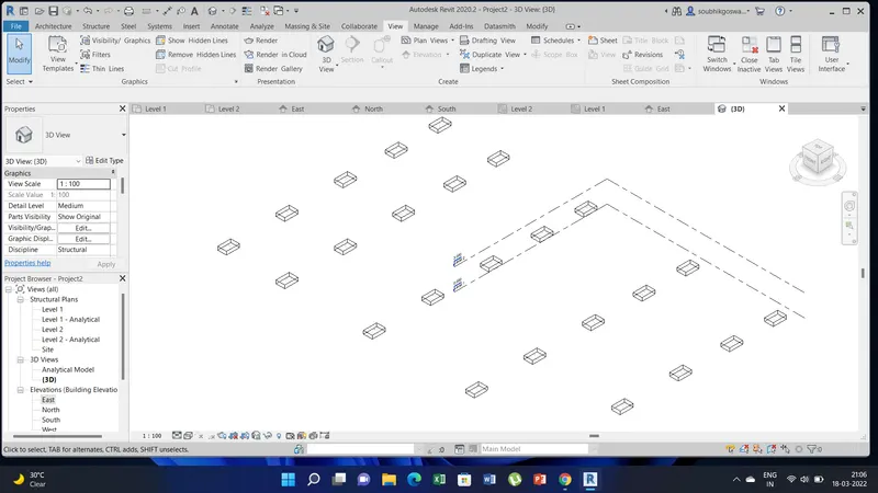
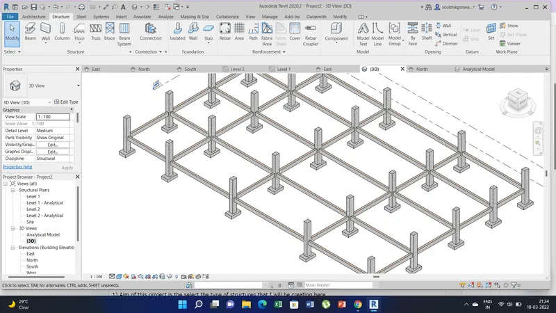
b) Now go to structural tab and select the type olf foundation we want assign. Here I have selected the isolated foundation.
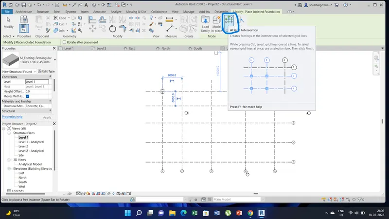
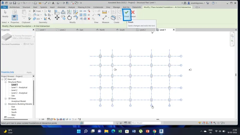
c) Select the level 1 at project browser and than select the isolated foundation. Now select the option at grid intersection than drag and click the all the grids and click the green tick. This will place all the foundation and respective grid nodes.
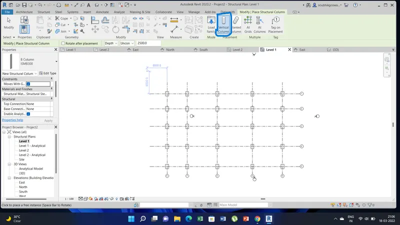
d) For columns again go to the structural tab and select the column from the ribbon menu under the structural tab. Here I have selected the vertical column and selected the specified size from the project browser option.
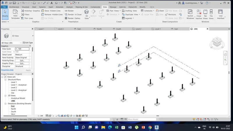
e) Now select all the grids and than assign all the columns in the intersection of the grids and than click on the green tick. To change the levels of the columns, from the project browser option select the top level as roof level-level 3 as per my model.
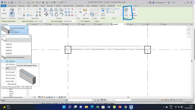
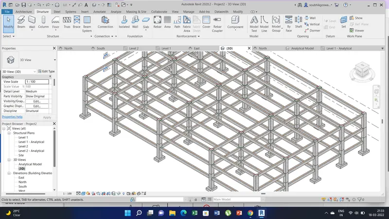
f) Now for creating the beams connected to the columns go to the structural tab select the beam option. And than select the type of beam. Here I have selected the concrete beam option.
g) Select the pick lin option and than click on on grid option. After that select the grids than click green tick. Following beams will be created the respective grid lines.
h) Similarly repeat the steps for other levels to create the beams on other levels i.e at level 2, 3.
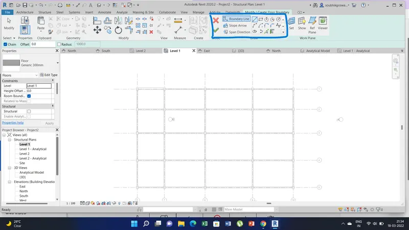
i) For roof framing, floor/deck go to the architectural tab select the floor option from the ribbon menu.
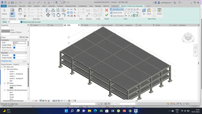
j) Now select the square draw tool from the modify tab and than click and drag the node of the model frame at level 1 from the columns/ grid nodes to the last grid nodes and than click the green tick this will create the floor. Similarly repeat the step at all the levels.
k) At the roof level I have created the structural slab by repeating the same steps.
l) For creating openings for elevators & Stairs we need to go to the structural tab and than select the shaft option from the ribbon menu.
m) Now select any levels and create the appropriate shaft with dimension as required by selecting the pick line option. Than adjust the shaft at respective levels as required. In this way we can create floor openings for elevators and stairs.
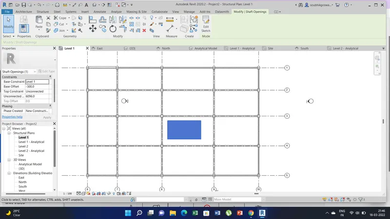
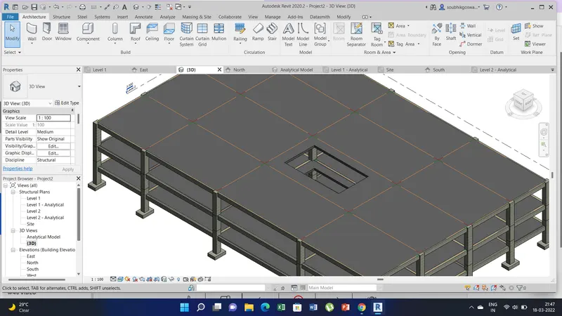
4) Aim of this project is to include components like wall layouts, Exterior façade with fancy finish,Interior partition walls to size rooms,Components to add details to a room ( Desk, Chair, Lighting, Plumbing fixtures), also add components such as stairs Elevators,have at-least one side of the building with curtain walls and glass panels, Include interior and exterior lighting fixtures, Place proper topographic components from outside ( Trees, Parking, Plants) to add details to the model.
Procedure:
a) Open the architectural file of office byuilding created. Now go to architectural tab and select the type of wall and create the walls along with the grid as per room layout.
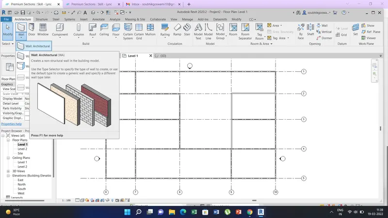
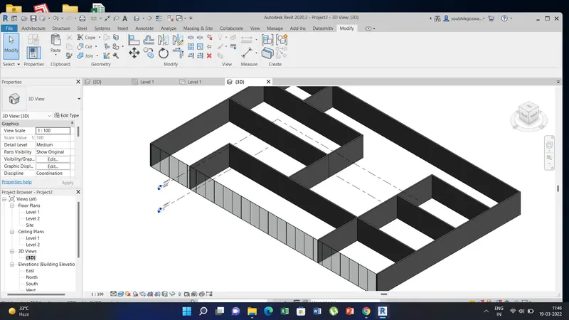
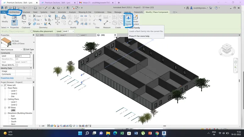
b) Go to architecture tab and than select the insert tab and load family option from the ribbon menu. Select the component you want to add like furniture, lighting, plumbing etc. Similarly add the other details like plants trees etc.
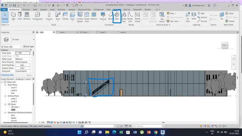
c) To add the components like stairs/ elevator you need to create the shaft and than put the stairs or elevator in the shaft area you have created.
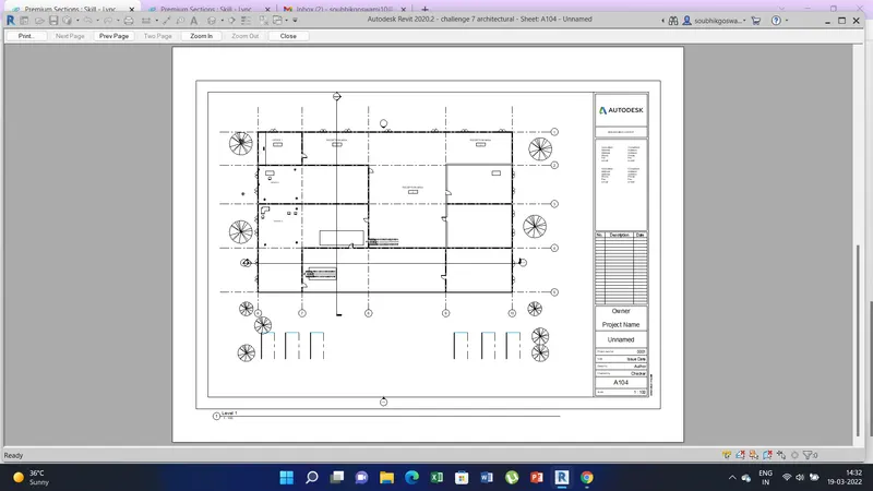
5) Aim of this project is to create a set of drawings in architectural and structural model for floor plans, section and elevation.
Procedure:
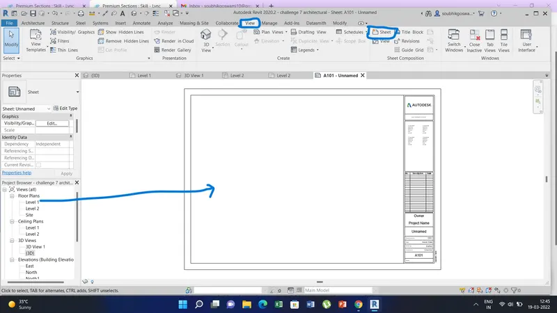
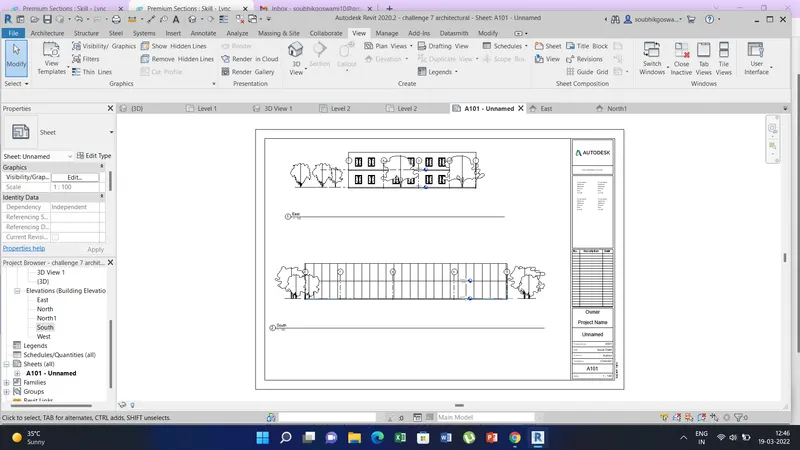
a) First go to the architectural model created. From the view option select the sheet icon.
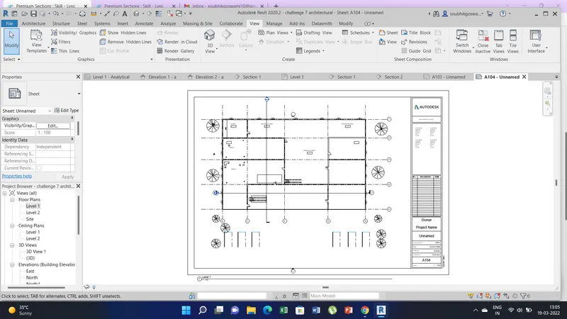
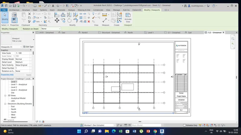
b) Create a new sheet and than drag the floor plan view from the project browser into the sheets.
c) Adjust the scale to place in the sheet area and than change the parameters in the sheet, rename the sheet etc.
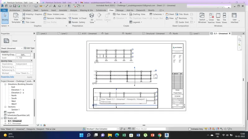
d) Similary do for the sectional views, elevation views for the architectural model in other sheets.
e) Similary open the structural model file and repeat the same procedure.
6) Aim of this project is to create the rendered image of the 3D model and create the sheets showing the rendered images.
a. Rendering from interior rooms
b. Rendering from out showing topographic features
c. Rendering through structural framing
Procedure:
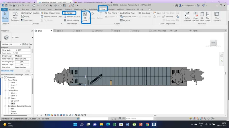
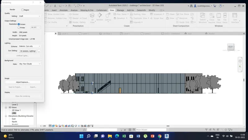
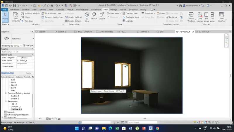
a) For rendering from interior rooms,outside rendering, structural frames etc. go to the 3d view select the camera option and place the camera in respective rooms where you want to render the views.
b) Now click on the render icon under the view tab. Adjust the setting liks sun path, lighting exposure etc. and than click on render. Now the view will be rendered.
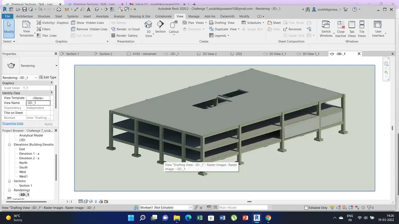
c) Similary for structural frame select the structural model, than go to the 3d views and than go to the view tab and click on the render icon. In the same way it will render the structural frame.
7) Aim of this project is to print the set of drawings from the sheet created from the architectural & Structural model.
Procedure:
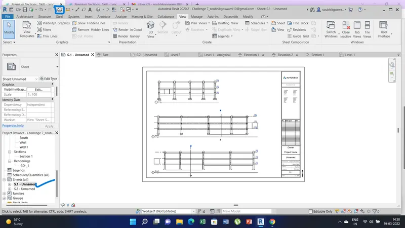
a) Select the sheets we have created in structural model.
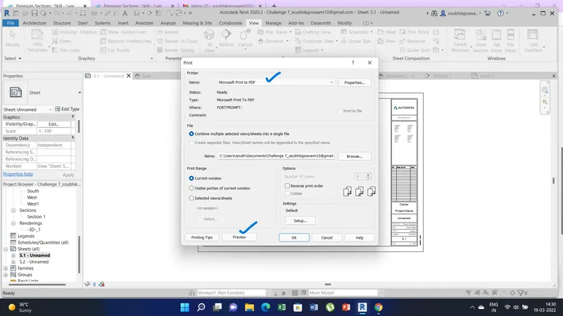
b) Now go the print icon option above and select the printer type or we can choose to print as pdf.
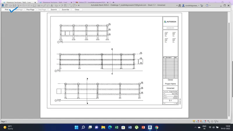
c) Preview the print and click ok to save the pdf file or we can print directly on the selected printer.
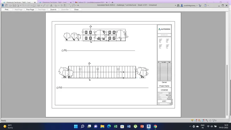
d) Similarly follow the same steps to print the other sheets in the structural and architectural model.