3D Creation of Celing, Roof, Architectural plan, Structural plan, Sectional view, Elevation view and Camera specific view for a house plan using REVIT
1) Aim of these project is to model a ceiling from the architecture tab above the walls at the first floor level.
Procedure:
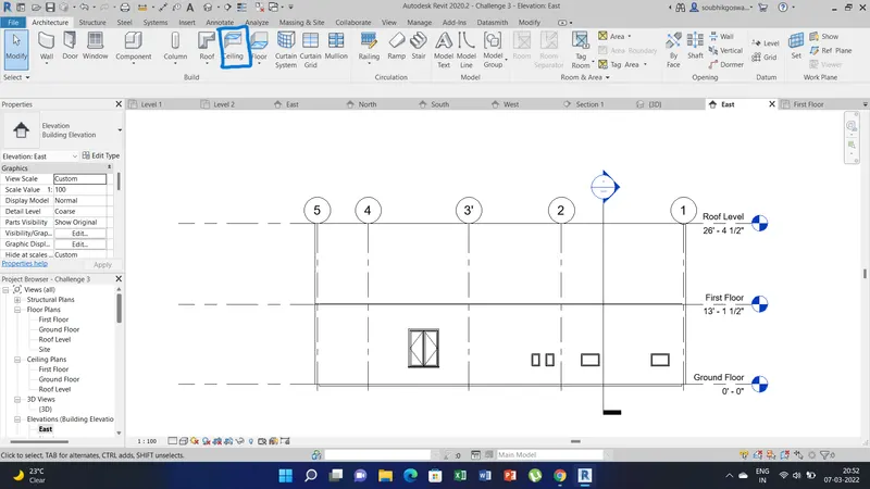
a) Open the week 3 project file and than go to architecture tab and than select the ceiling option from the ribbon menu.
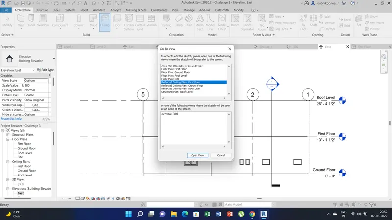
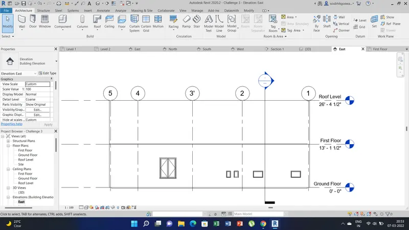
b) After selecting the ceiling a dialogue box opens there select the reference level were ceiling has to be placed here we have to place at first floor ceiling level.
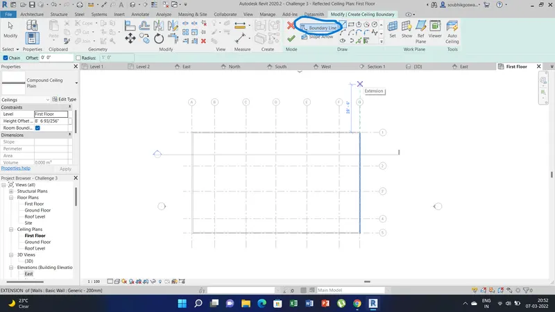
c) Now select the sketch ceiling option from the ribbon tab and draw the ceiling by boundry line option in the outer wall. To change the ceiling height go the properties there change the height values in the unconnected option. Than click the green tick to finalize the ceiling. After that the ceiling is created. Here I have kept first floor level height.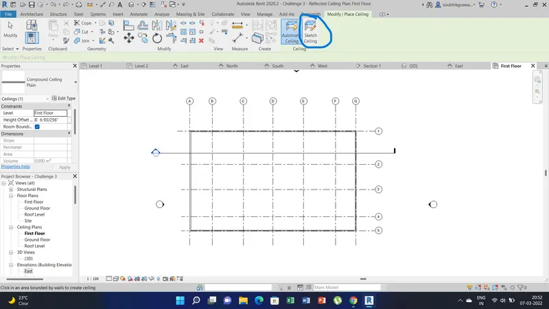
2) Aim of these project is to model a roof above the ceiling by selecting the footprints of the ceiling and also adjust the roof slope to 10 degrees.
Procedure:
a) Go to architecture tab and than select the roof option from the ribbon menu.
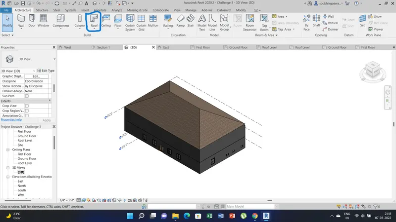
b) Now draw the roof by boundry line option outer perimeter of the wall at roof level and than click on the green tick to finalize the roof.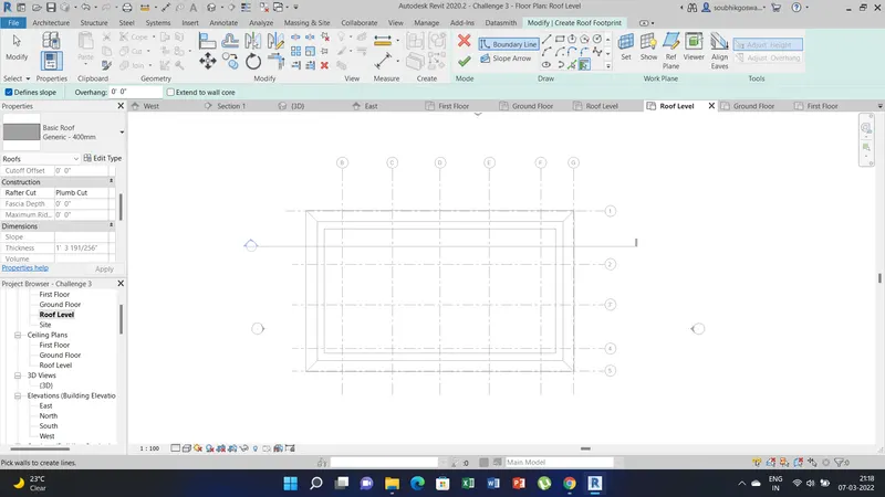
c) To change the slope select the roof and than go to properties box there scroll down to slope and than change the slope to10 degrees.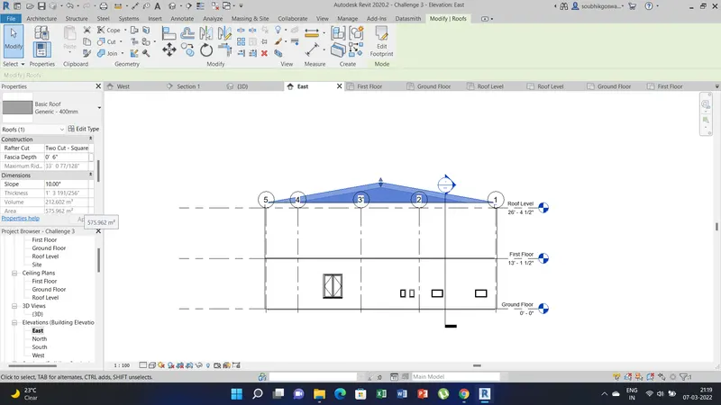
3) Aim of these project create plan views for ground floor level and first-floor level including all the walls, floors, and components also separate them toarchitecture and structural plans.
Procedure:
a) Go to the view tab and than select the plan view option.
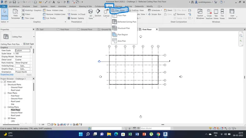
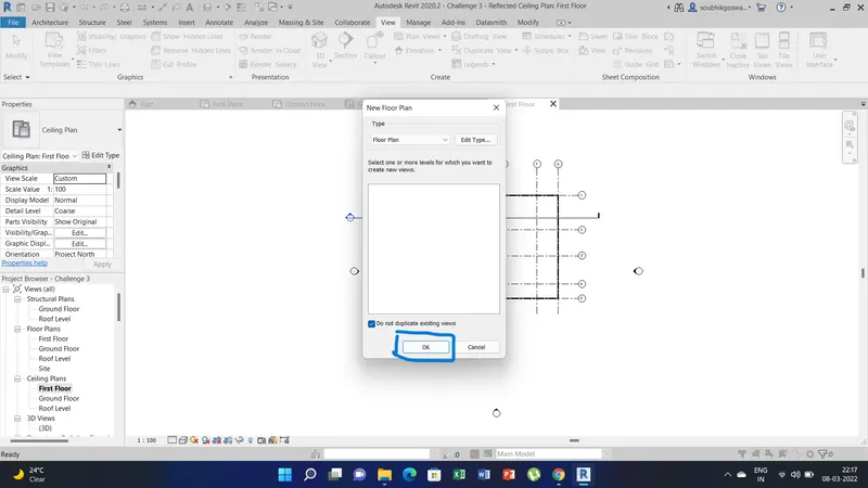
b) Now select the Floor plan option and click the option ok in the dialogue box.
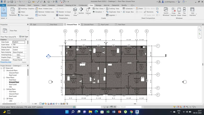
c) Now for structural plan go to project views option and than select the structural plan and click ok in the dilogue box.
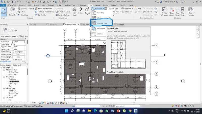
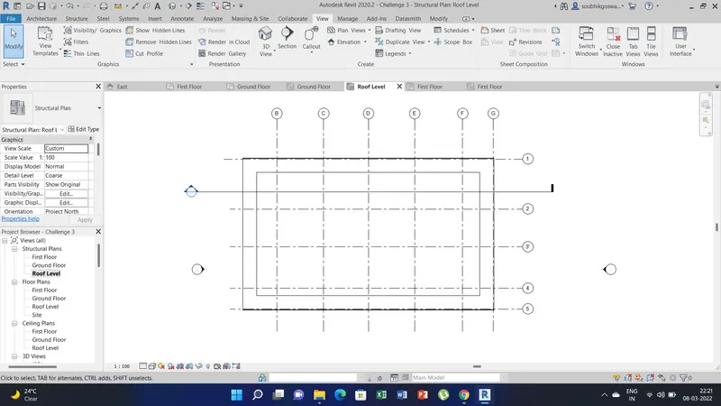
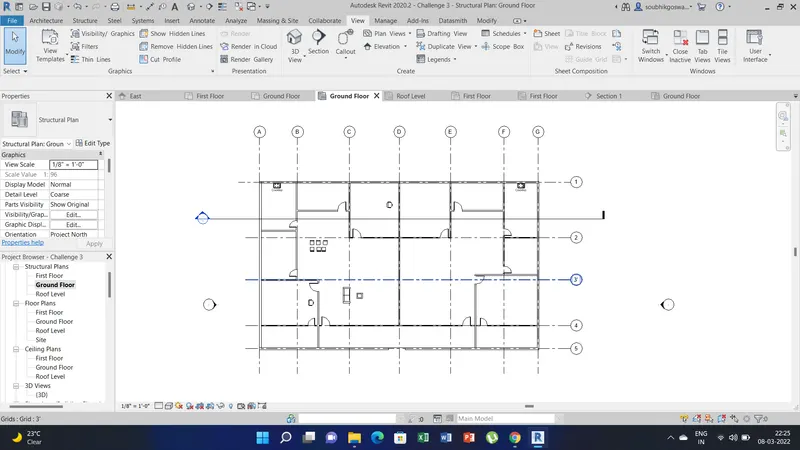
d) Now in structural view in project browser click on the roof level in structural plans and it shows only the structural materials associated in the model. Similarly in the floor levels it only shows the structural wall associated with the model.
4) Aim of these project is to use annotate toolbar for adding dimensions to all the walls and floors with reference to the longitudinal and transverse grids created in the project file.
Procedure:
a) First select the architectural plan Ground floor than go to the annotate tab.
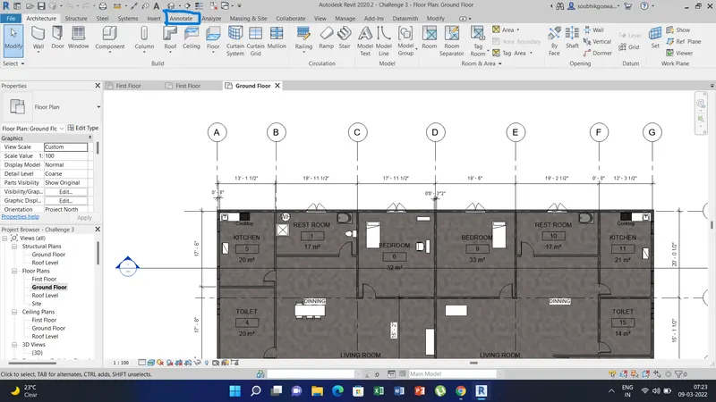
b) Select the aligned or linear dimension and place dimension as required by selecting one end point along the wall and than click and drag place at end point. Dimension will show up as you have placed.
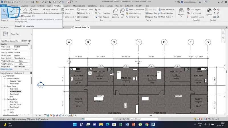
c) Similarly for structural plan select the structural plan in project browser and than again go to anotate tab.
d) select the aligned or linear dimension and than place the dimension in structural plan.
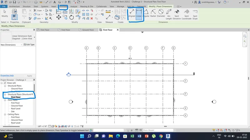
5) Aim of this project is to create a sheet template from the view tab and adjust the parameters on the sheet to add appropriate views.
Procedure:
a) Select the view tab option and go to sheet option and select the sheet option from the ribbon menu.
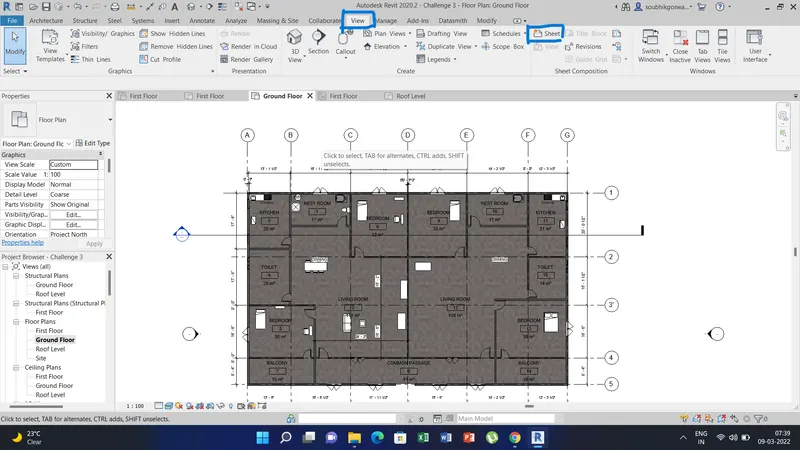
b) Now select the type sheet we want here I have slected A1 size and than click ok.
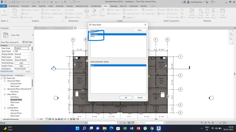
c) Now edit the sheet details name, date etc. by clicking on the details and rename as required.
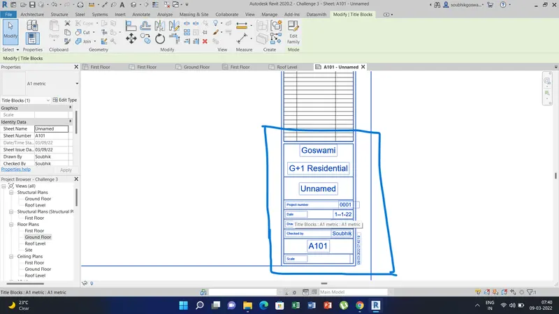
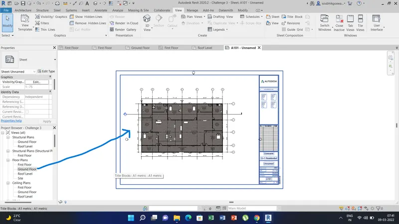
d) Now drag and drop the plan view from the project browser and than place it in the sheet area. Here I have placed ground floor view.
e) Adjust by moving the frame box and adjust the scale from the project properties to fit the plan view in the sheet area.
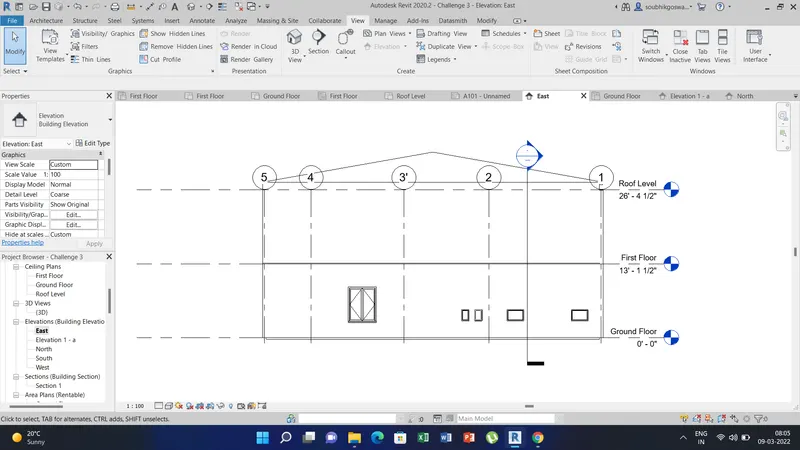
6) Aim of this project is to use the elevation tab to create the elevation views, looking at the building from East, North, South, and West.
Procedure:
a) Go to view tab option and than select the elevation option from the ribbon menu.
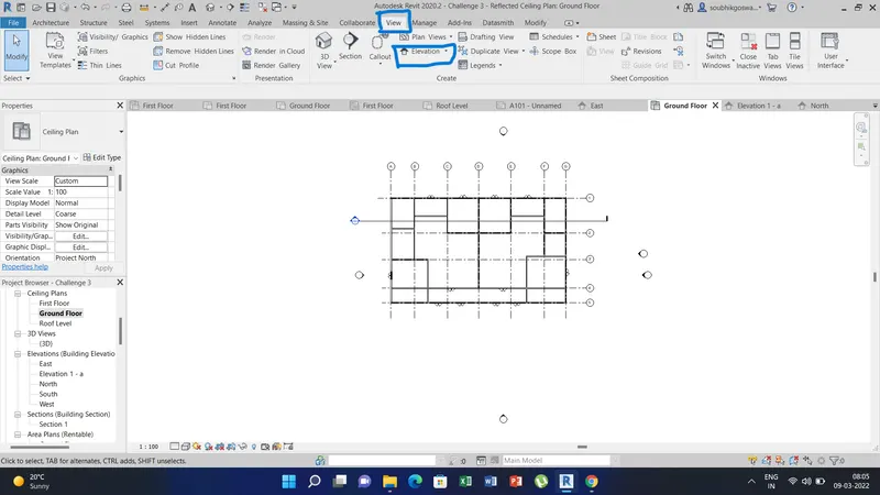
b) Now place the elevation icon where you want to view the elevation, a new elevation will be created in the elevation list in project browser. By default revit creates four elevation i.e. East, west, North & South.
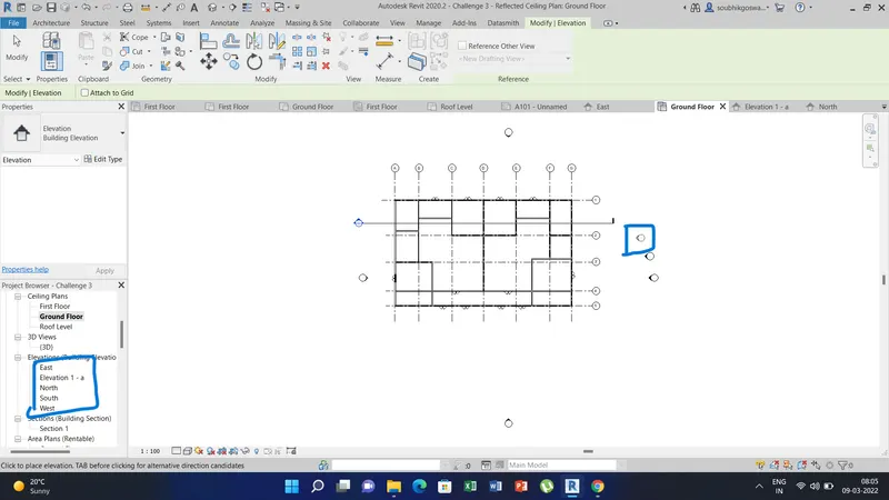
c) To view the elevation select any of the elevation East, west, north, South.
7) Aim of this project is to create section cuts through each room either cutting along the longitudinal direction or along transverse direction.
Procedure:
a) Go to view tab option and than select the section cut option in ribbon tab.
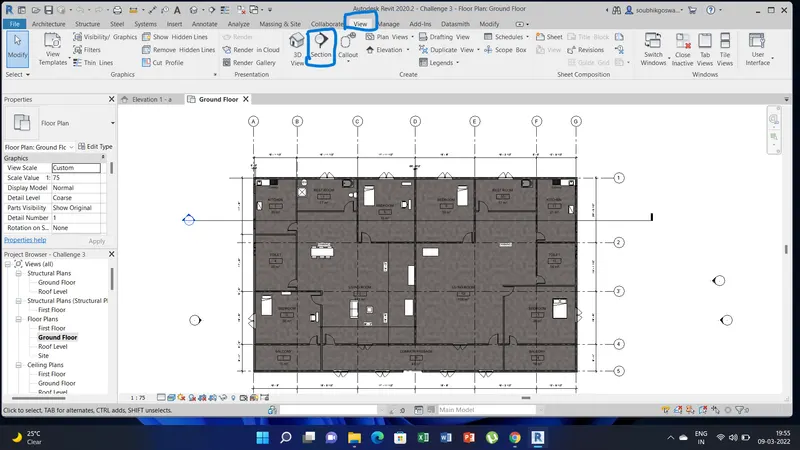
b) Now cut section along transverse and longitudinal section in individual rooms.
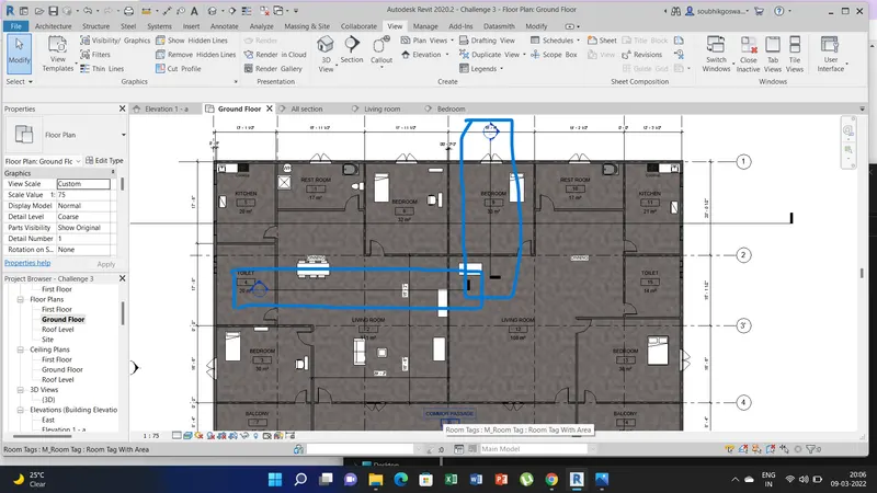
c)Rename the section in project browser as living room, bedroom where the section has been cut.
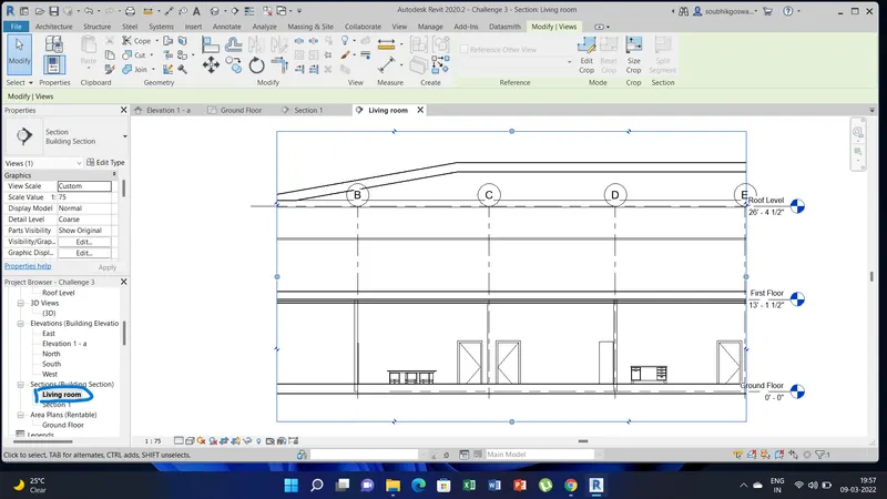
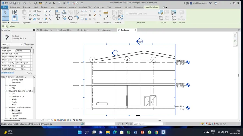
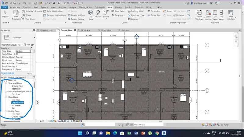
8) Aim of this project is to classify the views, Plan Views, Section Views, and Elevation views to either Design or Documentation category using Properties browser.
Procedure:
a) Go to the project browsers option.
b) There list of view has been classified as shown in the screenshot.
9) Aim of this project is to create multiple sheets using sheet template and also add additional sheets based on the sections created.
Procedure:
a) Go to view tab and select the sheet option from the ribbon menu.
b) Click on Sheet A1 and click ok. The new sheet is created.
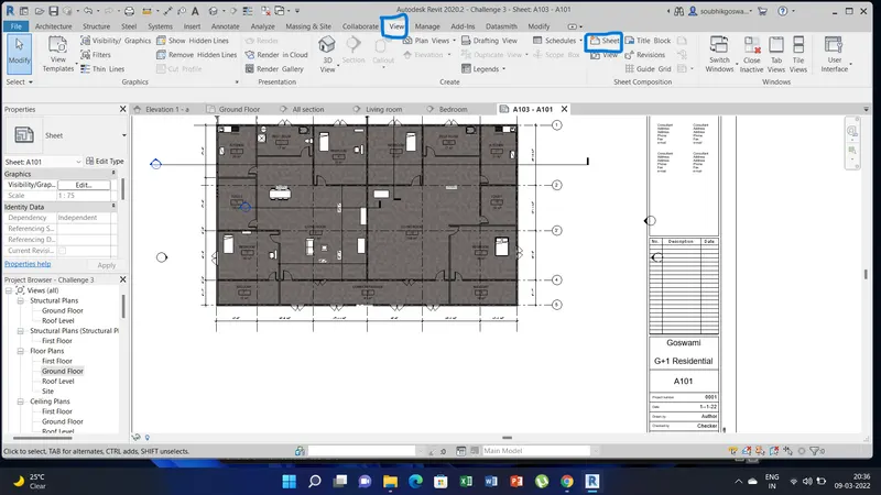
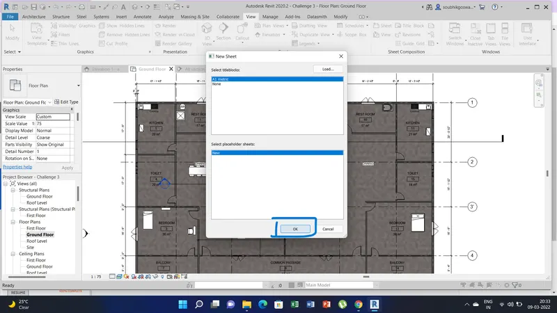
c) Now go to the sheet and rename as A101 as sheet name.
d) Then drag and drop the architectural ground floor and change the scale to fit the plan in the sheet area.
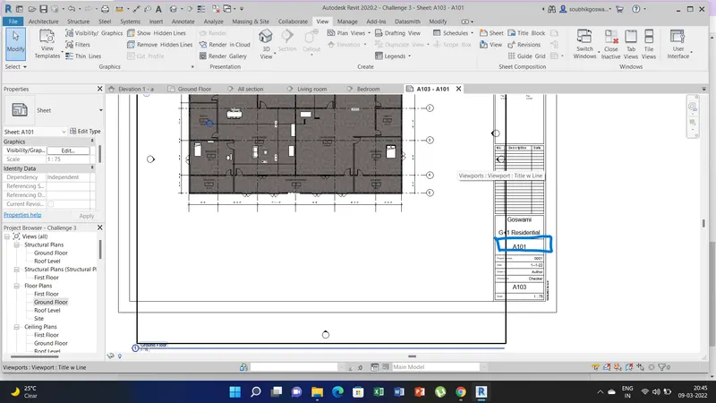
e) Similary create other sheets as per question and rename the rest of the sheets. It has been shown in the screenshots below.
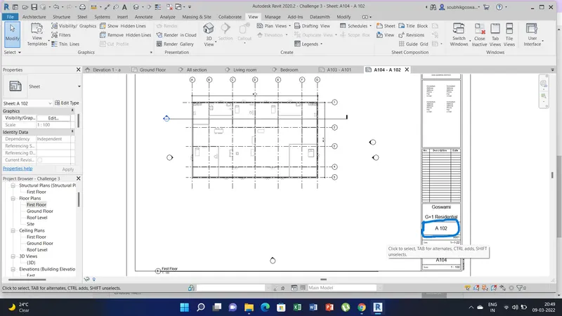
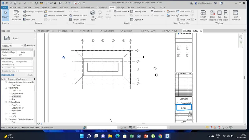
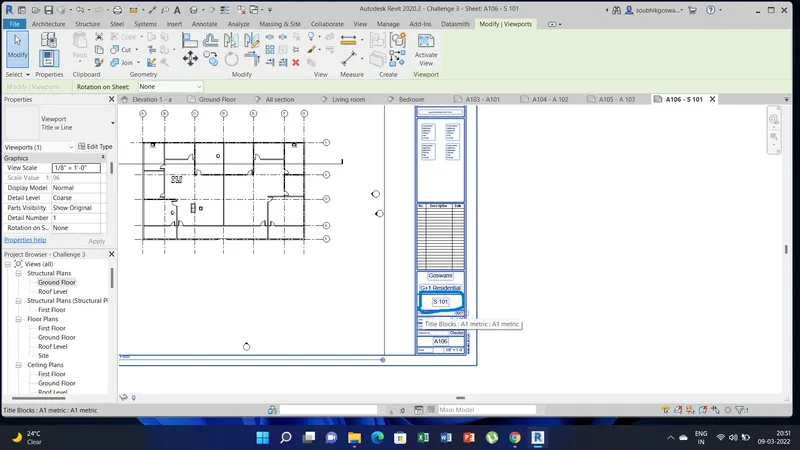
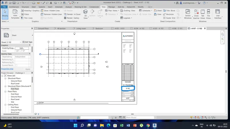
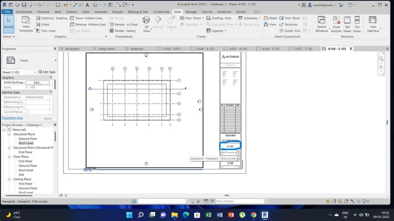
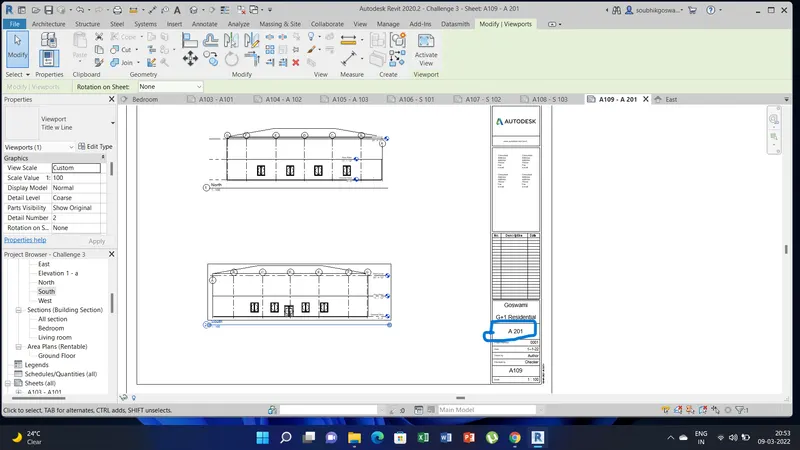
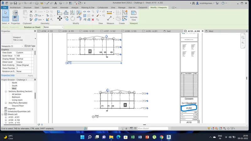
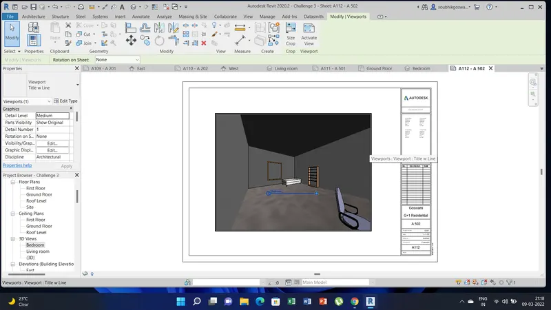
10) Aim of this project is to create a camera-specific view or a 3D view in each room ( living, dining, bedroom). Based on the views also create a new set of sheets starting A-501 (you can add as many sheets after, 502, 503.. n)to place the 3D view images.
Procedure:
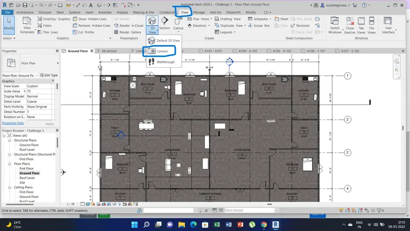
a) Go to view option tab and than select the 3d view from the ribbon menu and than select the camera option
b) Place the camera in floor plan and extend the view as required. Here I have placed the camera in the living room.
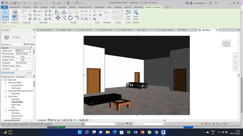
c)Now go to the view option and than select the sheet from the ribbon menu. create the new sheet and rename it as A 501 in the sheet name.
d) Go top 3d view in the project browser and select the view and rename it as living room in the project browser. Now drag and drop the living room 3d view to the sheet A 501.
e) To change the size of the image go to size crop option in the ribbon menu and change the size as required to fit the image in the sheet.
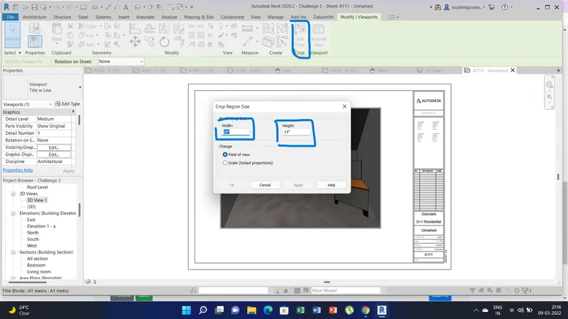
f) Similary follow the same steps to create other room views and rename the sheets as required. Here I have done for bed room and sheet name as A 502.