Creating Architectural and Structural model with 3D rendering using REVIT
Q1
Answer:- I have selected a multi-story residential building for my project from the given options
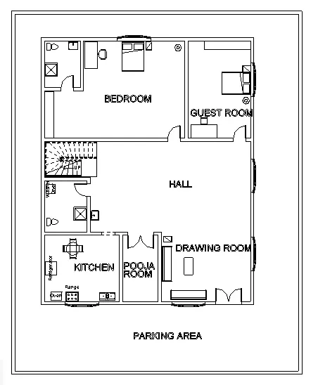
- GROUND FLOOR PLAN
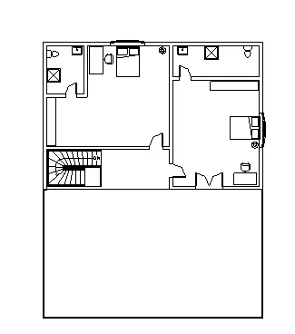
- FIRST FLOOR PLAN
Q2
Aim:- to design the project as per the guidelines of NBC
- As per NBC guidelines the setback distance should be provided as per the norms of the municipality in that location and i have given a setback of 6' on every side
- the residential unit should be provided with good ventilation and lighting for which I have placed a window in each room
- accessibility should be provided properly
- to access the first floor I have placed a staircase
Q3
Aim:- To create a structural model including the components such as
- footings
- columns
- beams
- slabs
- stairs
step 1:-To create a structural template
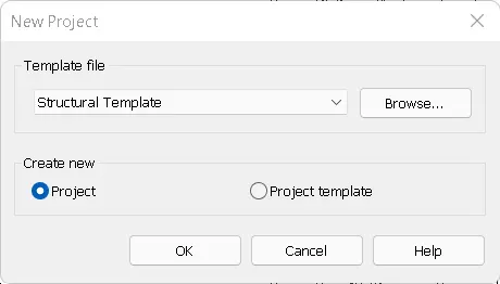
- open revit>new
- select the template as a structural template
- click on OK
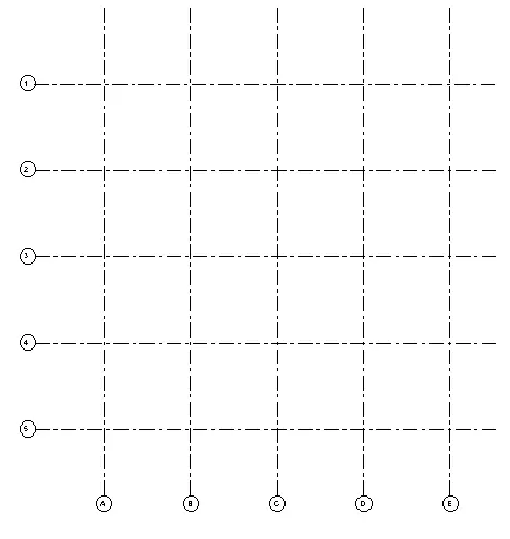
step 2:- To create grids and levels
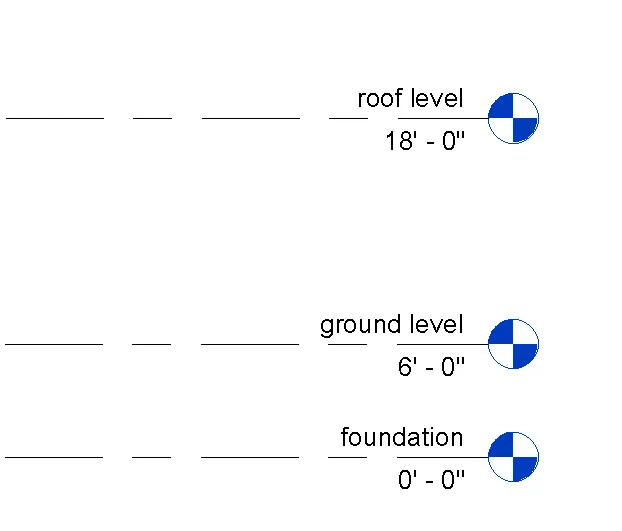
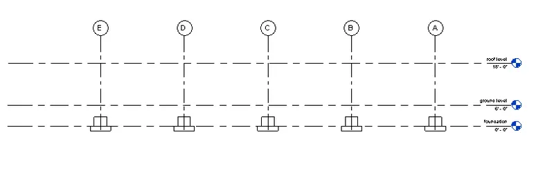
- open the elevation view
- go to the architecture tab
- select datum>levels
- specify the height of the levels as oper the design requirements
- go to the architecture tab
- select datum>grids
- select an appropriate offset and draw horizontal and vertical grids
Step 3:- to place a footings
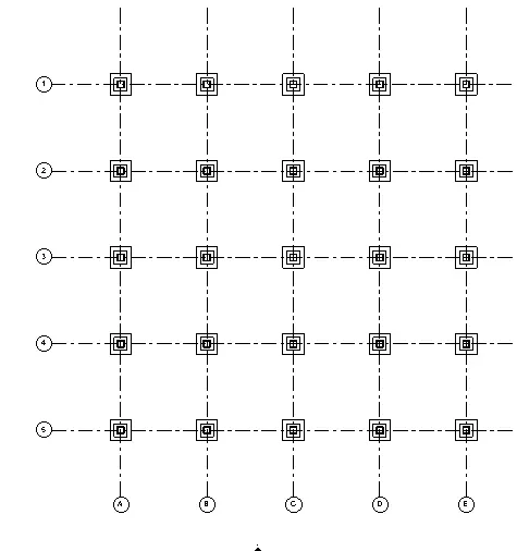
- go to the structure tab
- select footing>isolated footings
- place at the grids
Step 4:- to add columns to the model
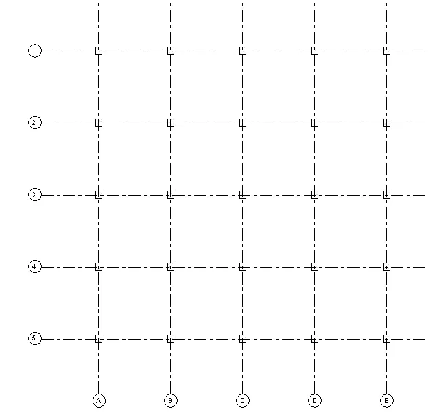
- go to the structure tab
- select columns>rectangular columns
- place at the grids
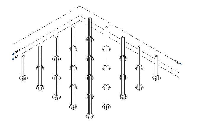
Step 5:-to add beams
- go to the structure tab
- select beams>rectangular beams
- place at the grids
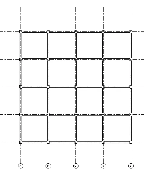
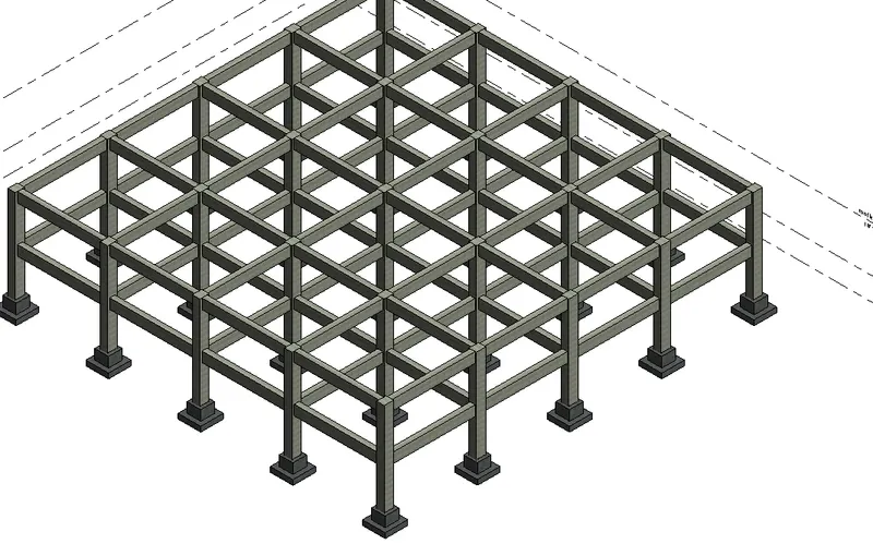
Step 6:- to add truss member at the desired location
- go to the structural tab
- select truss
- place at the desired location
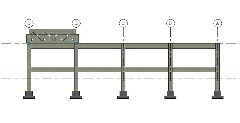
step 7:- to add roof?/slab to the structural model
- go to the structural tab
- select floor
- add the levels to the structural plans
- pick the boundary lines
- click on finish
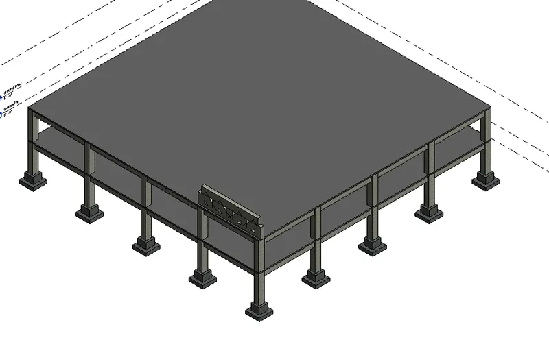
RESULT:- the structural model with elements like column, beam, footing, truss, and slab ae added
Q4
aim:- to create an architectural model with all the components, lighting, and topographic details
- go to the view tab
- select sheet > load the desired sheet size
- drag the view and place over the sheet to the required scale
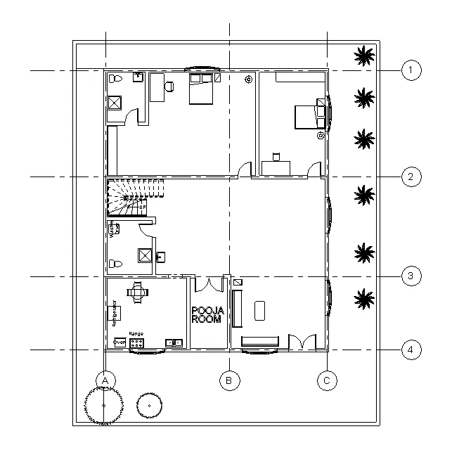
RESULT:- the components mentioned in the question like seating arrangements, partition walls, tables, and other components, topographic details, plumbing fixtures, and ventilations are added to the architectural model
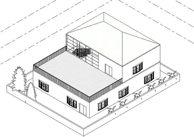
Result:- the elements like a staircase, curtain wall, railing are added
Q5
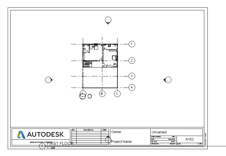
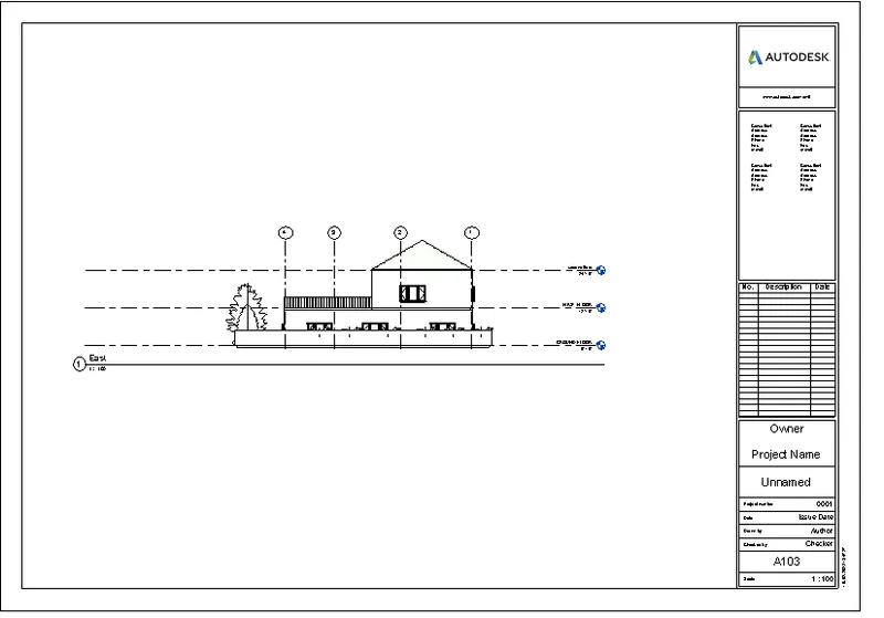
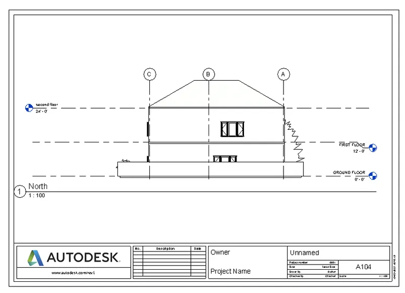
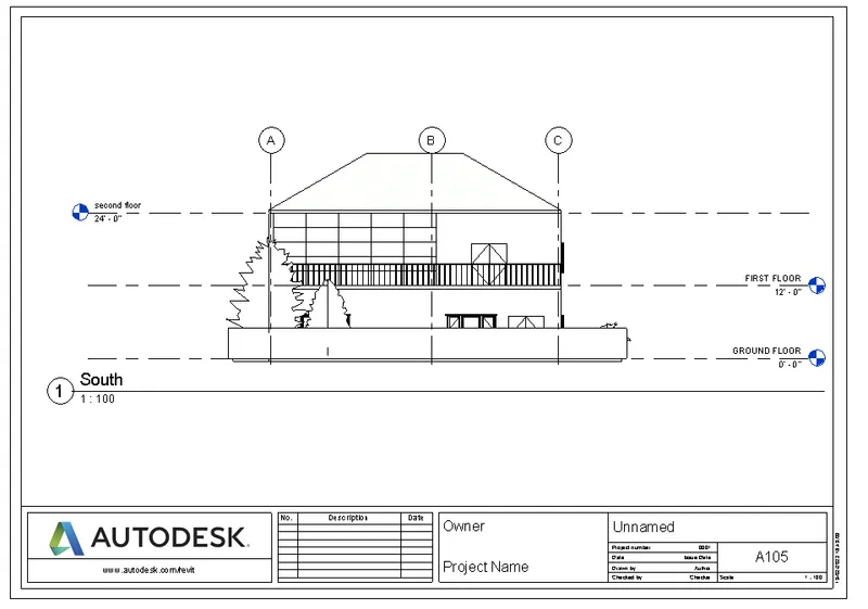
Aim:-to create sheets of the floor plans, elevation views, and sections
- floor plan views
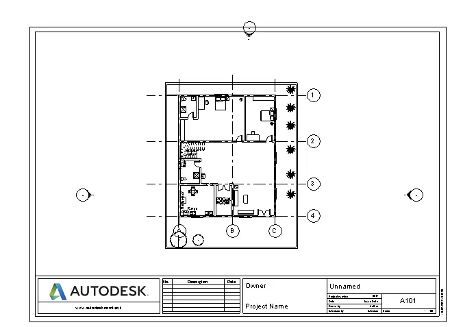
- elevation views
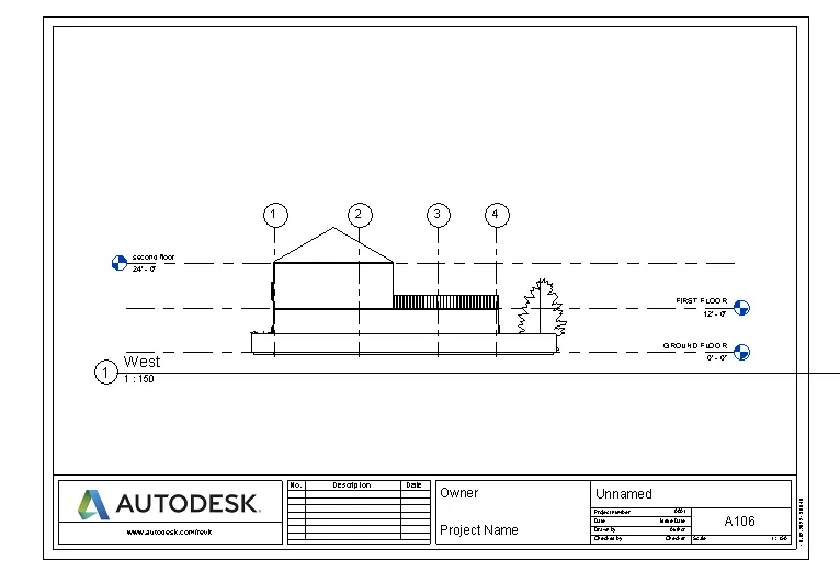
- section views
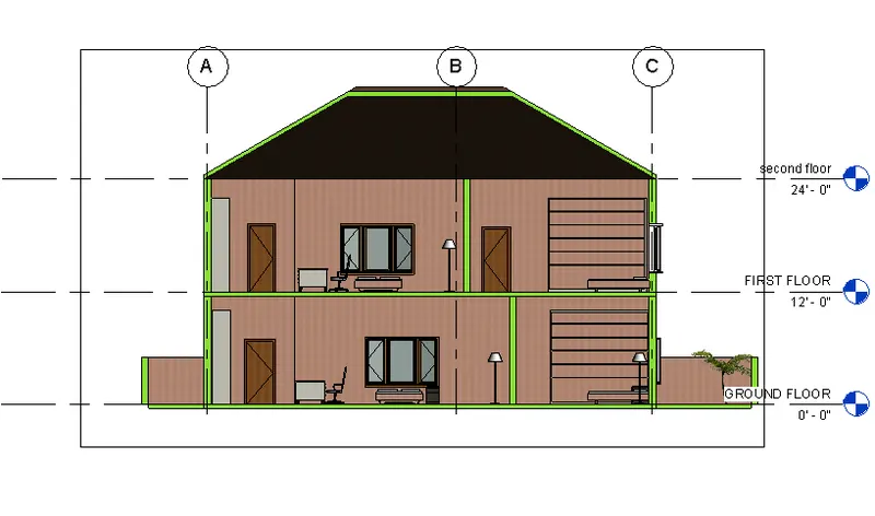
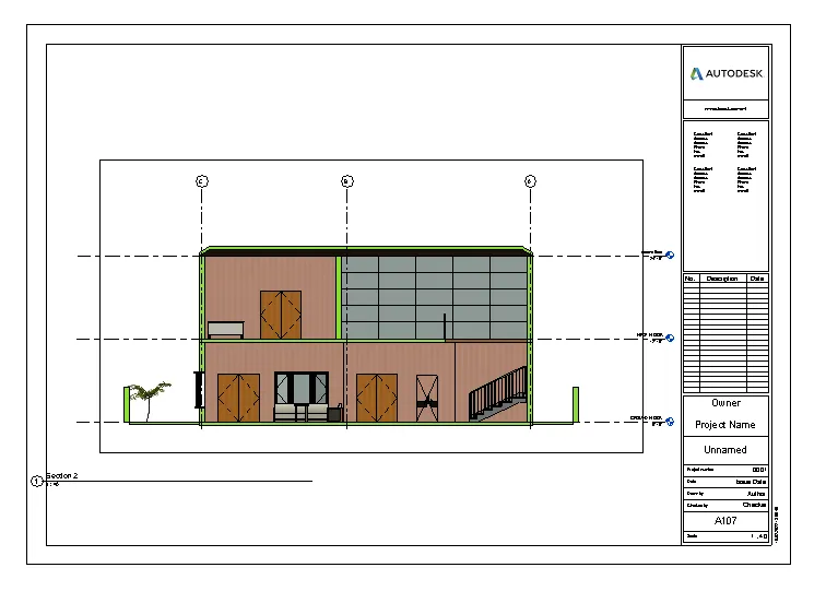
RESULT:- the sheets of floor plans, elevation views, and sectional views are created
Q6
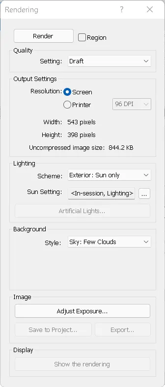
Aim:- to render the 3D images
- go to the view tab
- select the render
- adjust the lighting and other renderings setting
- then click on render
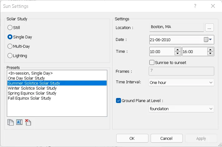
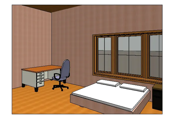
RENDER IMAGE OF THE INTERIOR DETAILS
RENDER AN IMAGE OF THE EXTERIOR ELEVATION DURING THE DAYTIME UNDER SOLAR LIGHTING

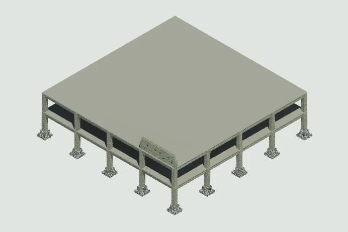
RENDERING THROUGH STRUCTURAL FRAMING
Q7
AIM:- to print the set of drawing sheets created
- go to the file tab
- Click on print
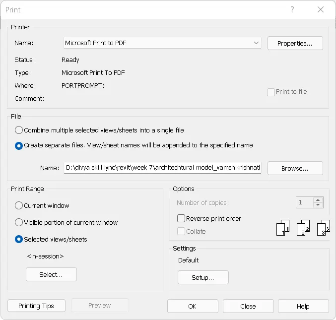
select the views you want to print
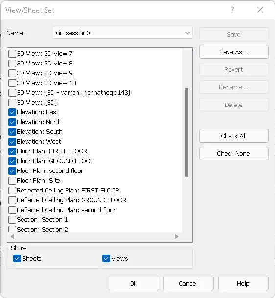
click on ok
then save the files to the folder
Result:- the pint out of the desired views are saved