Creating an Architectural plan for the provided plot size and develop relevant basic structural drawings
AIM : TO draw and drats a layout of a residental building with the following details plot size of 18.3*6m facing east
procedure : 1 open autocad
2 open new sheet from the home rebbon
3 select the units
4 select the limits from0,0
5 select the rectangle from the home rebbon and draw a rectangle of dimentions 18300/6000
6 now select the offset command and give a offset of 300 to make the externall wall
7 now go to the layers and create a layer with a colour and give it the name external wall
8 now select the externall wall and make to the exwall lyer current
9 now from the externaal wall give a offset at a distance to make the dra wall at a distance of 5850 from the right exwall
10 now div the rec into two parts by giving a offset og 3000 from the upper exwall
11 give a offfset of 150 to make internel wall thicknes
12 now in the upper part of the rec we neend too draw stairs
13 now draw a line by giving a offset from the upper extternall wall at a dostance of 1500
14 now leave a distance of 2750 and strt drawing steps with the use off ofset command at a distanceof 350 at each step
15now select the snap option and select the mid points of the steps to join the line and corner points to create landing
16 now go to the layers and create a new layer of steps
17 now select all the stepsyou want to put in staris layer nd give it a colour the stairs will become of that colour
18 now from the internal drawing room wall give a offset at 4000 to make the internalkitcen wall give a offset of 150 mm to make internal wall thickness
19 now give a offset of 2800 to make the kitchen and use the trim command to trim the remaining unwanted lines
20 now from the lower ex wall give a offset at 3000 to make the breadth of the kitchen wall
21 now use the triim command remove the extended lines
22 now from this wall give a offset of 3850 to make two bed rooms
23 now from the upper wall give offset at 3000 to make the division inner wall of 150 mm thickess bitween two bedrooms
24 the remaing areais of the toilets give a offset of 270
25 now use the trim and line command to make the doors where ever is reqired
26 use the arc start end direction to make the swing of the door
27 now use the line tool to make windows use the copy and move tools to place windows where ever it is required
28 now go to the layers and make the layers of diffrent for door, windows, interwall
29 give diffrent colours to diffrent layers
30 now select the items you want to put in different layers
the dimentions
total area is of 18300/6000 mm
toilet is 270/3000
bedroom 2850/3000
bedroom2 2850/3000
kitcen 2800/3000
liv 6600/6000
draw of 5850/3000
use the mtextcommand gto write the text on the diagram select the height of the text
result 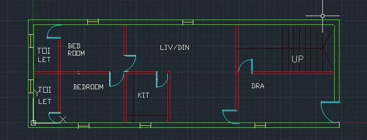
31 now to make the elivation of the building draw a line in the x diection of height h
32 now draw a line of h=6000
33 now leave a distance od 4200 from the right side and start drawing the stairs raise of the step is 600 m and b is 500
34 draw the steps and give a landig of 1700 in between
34 now change the direction of steps and draw till it reaches te height of 6000
35 now div the x line in 4 parts and draw pillersin bitween
36 in the left side of the draw a window by using the line command two draw a window
37 in the center draw a gate by use of line and snap command
38 now in the right draw a door using the rec command
37 now select the copy option and parts you want to copy on the top floors and put it on one another
38 now usee the offset option to make the balcony grill design in between copy that design inupper floor
39 at the topof the building draw a rec and use the mtext command to write the text
40 use the trim option to remove the unwanted lines
41use the leader to show the height of the slabs
42 give a offset of 500 at line of 6000 to make slb thickness
43 to increase the leader size go to the propertys and increase the leader size to 1000
result 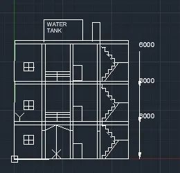
44 now to draw the secton div the diagram by using x and y direction lines
45 now from the meeting points of x and y line draw the things which are visible
46 the visible things are a door winddow all door window
47 result 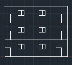
48 now to drawthe coloumb plan draw the grid line over the the layout plan
49 now select the copy option and select the grid lines
50 now use the move command to move the grid lines to diffret place
51 now where the grid lines meet mark those points with the help of square of 1000,1000
52 now place the square over every intersection points of the grid lines
53 now use the hatch commmand
54 select the hatch pttern
55 now select the hatch scale
56 now hatch all the squares
57 now use the mtext command
58 give the h of thetext
59 now givve the rotation angle 0
60 now select where you want to wwrite
61 mark all th coloumbs rom c 1 to c 18
result 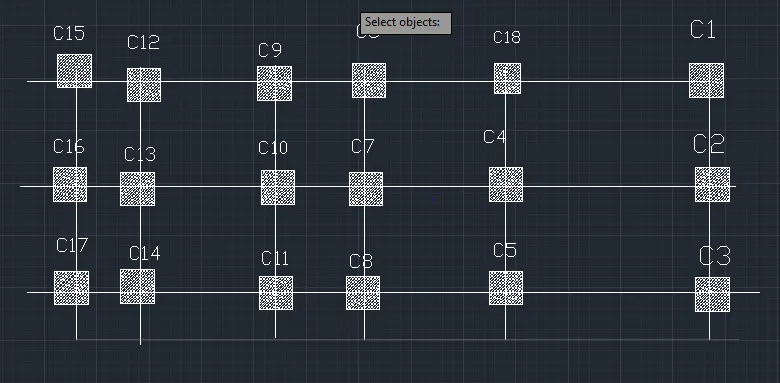
62 now use to draw the beam plan select the copy option and select the grid lines
63 beam is the connection between to coloumbs
64 use the offset command to define the conection between the coloumbs
65 use the single text command to write the numbering of the beam
66 give the h of the text now give the rotation angle
67 now give the numbering of the beam from b1 to b24
reult 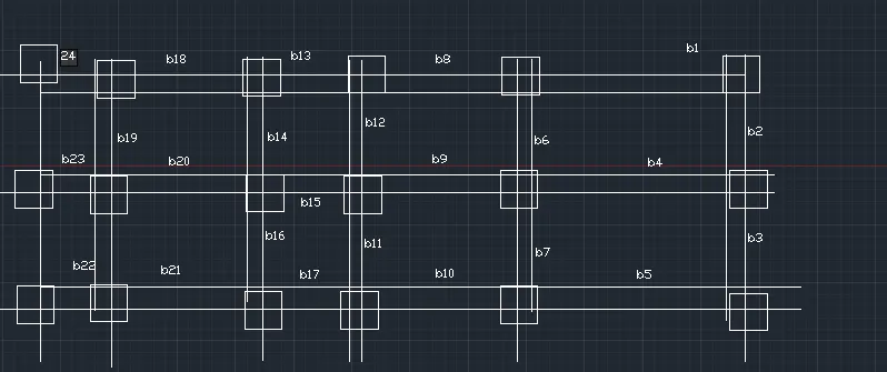
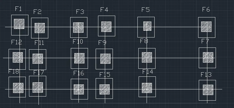
68 to draw the footing plan we neend to draw the grid lines over the layout
69 select the move option to move the grids
70 now footing comes below the coloumb
71 draw a rec of any maeasurment and place it at the coloumbs
72 NOW USE THE SINGLE LINE textr to write the text over the footing
result